I can't thank him enough for the opportunities he has given me to learn, build character and light a fire. In addition, I would like to thank my entire family for the encouragement they provided me every step of the way.
Introduction
Magnetorheological and electrorheological brakes provide improved torque and weight characteristics compared to magnetic particle brakes, but sacrifice bandwidth and dynamic range relative to MPB. The thesis presents the design of an electrically actuated proportional brake that provides a significantly improved torque-to-weight ratio compared to a magnetic particle brake, while maintaining (or improving) dynamic range and response time.

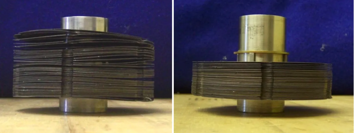
The main unknown in this first waffle disc brake prototype was the performance of the discs. The dynamic performance of the brake was not evaluated due to inconsistency in ball screw retraction.
BRAKE DESIGN ITERATIONS
Wafer Disc Brake Prototype 1
- Design and Operation
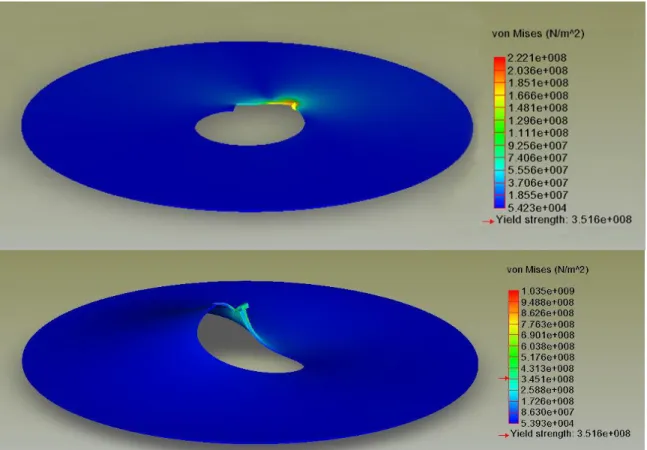
- Finite Element Analysis
- Performance
- Conclusions
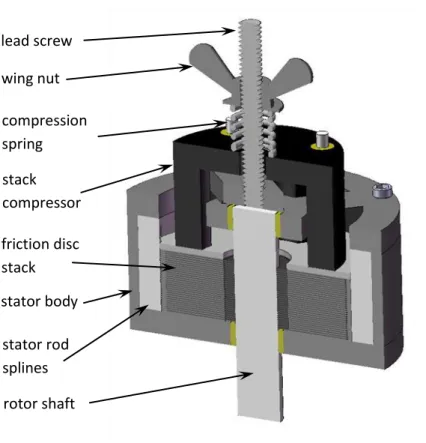
Knowing the spring constant and the speed of the lead screw, a predictable force can be applied to the friction disc stack via an interstack compressor piece. Of particular concern was the stress concentration at the keyway of the rotor discs (i.e. where the discs connect to the rotor shaft).
Wafer Disc Brake Prototype 2
- Design and Operation
- Performance
- Conclusions
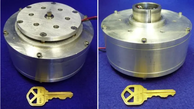
In addition, the rotor shaft was hollow, allowing all actuation components to fit concentrically within the shaft to reduce the braking profile. Excellent static maximum and minimum torque values were obtained from the brake after the disc heat treatment and grinding process.
Wafer Disc Brake Prototype 3
- Design and Operation
- Performance
- Conclusions
One further design change from the second to the third prototype involved the choice of the ball screw. Strain gauges applied to two opposing arms of the compression star to provide force feedback on the disc stack.
Conclusion
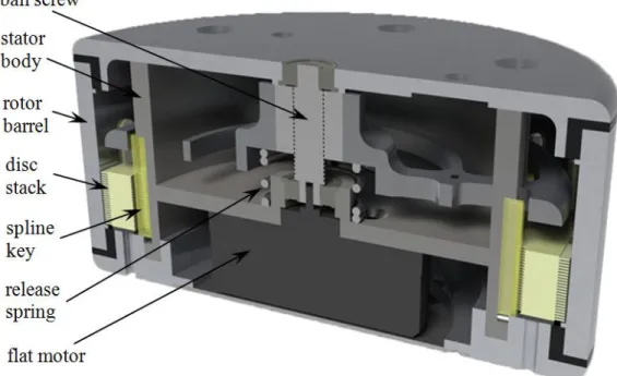
The design of a normally locked brake is similar to a normal non-locking brake, but the discs are preloaded by a compression spring. This article describes the hybrid approach of FES and the design of a fused orthosis.
MANUSCRIPT I: DESIGN OF A MULTI-DISC ELECTROMECHANICAL BRAKE
Abstract
After the description of the device, experimental data are presented to characterize the operation of the brake. The performance characteristics are then compared to those of a commercially available magnetic particle brake of comparable size.
Introduction
This paper presents the design of an electrically actuated proportional brake that provides a significantly improved torque-to-weight ratio relative to a magnetic particle brake, while maintaining (or improving) dynamic range and response time. The remainder of this paper describes the design of the (wafer disc) brake and characterizes and compares its performance with that of a commercially available magnetic particle brake of comparable size.
Wafer Disc Brake Design
- Brake Configuration
- Design Relationships
- Special Considerations for the Normally Locked Design
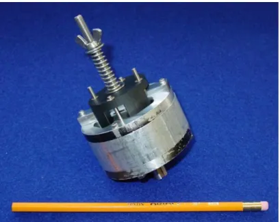
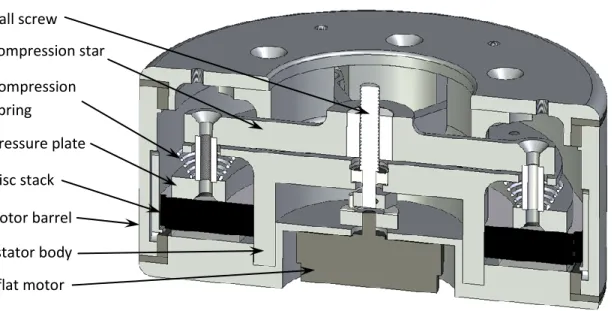
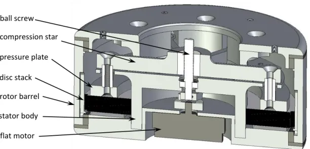
A small brushless motor located inside the brake stator transmits a compressive force to the stack through a ball screw. Due to the serial arrangement of discs, the resistance torque on the rotor barrel is the product of the thrust force, the average contact radius and the coefficient of friction, which is amplified by the number of contacts between discs. Since the ball screw is reversible, the braking torque remains inversely proportional to the motor current.
For example, the normally locked brake can exert a maximum of 264 N on the disc stack in the non-driven state, which is approximately 3.5% less than that of the normally released brake at maximum power.
Brake Control
Furthermore, by providing improved output disturbance rejection, the inner loop mitigates the effects of the varying load stiffness on the stability of the closed loop. Note that since the brushless motor includes Hall-effect sensing for electronic commutation, the implementation of the inner loop did not require the addition of any sensors. With the inner loop in place, accurate and robust tracking of the pressure plate movement is provided.
However, due to the three-sided stiffness mentioned above, the pressure plate movement control does not provide the known control of the pressure force.
Performance Characterization
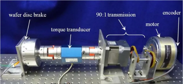
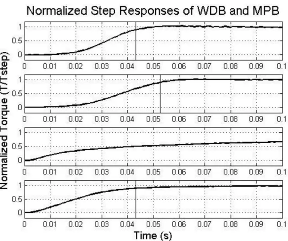
The maximum dynamic torque of the normally closed brake could not be measured in one of the two ball screw operational regimes due to insufficient in the. As previously discussed, the normally closed brake torque was predicted to be slightly lower than that of the normally unlocked brake. Note that since the output of the WDB is a barrel rather than an axle, the brake is connected to the setup.
An experiment was conducted to determine the power dissipation capacity of wafer disc brakes, the results of which are shown in Fig.
Comparison of Wafer Disc Brake and Magnetic Particle Brake
During the second half of the swing phase, the hip is locked with the hip brake while the knee is extended by stimulating the quadriceps group. The JCO design includes a Bowden cable that runs along the inside of the femoral connection and attaches at both ends to the hip and knee rotors (see Figure D-2). The dynamic simulator has two main parts — the human body model and the gait controller.
The distance is a fraction of the segment length. All units are in the MKS system. The knee torques are the result of a combination of quadriceps stimulation, joint coupling, the knee joint spring and the resistive torque of the brake. The JCO design includes a Bowden cable that spans the inner thigh joint and attaches to the hip and knee rotors.
Experimental measurements further indicate a minimum torque of 0.16 Nm (i.e. the dynamic range of the brake is between approximately 0.2 and 50 Nm). About half of the orthosis weight is on the pelvis and thus does not contribute significantly.
Conclusions and Recommendations
Du, "Design and Experimental Evaluation of a Magnetorheological Brake," The International Journal of Advanced Manufacturing Technology, vol.21, issue 7, pp.508-515, May 2003. A hybrid functional electrical stimulation (FES)/orthosis system is being developed that combines two channels of (surface electrode-based) electrical stimulation with a computer-controlled orthosis with the aim of restoring the gait of spinal cord injured (SCI) individuals (albeit with a stability aid, such as a walker ). The orthosis is an energetically passive, controllable device that couples 1) unidirectional hip-to-knee flexion; 2) assist hip and knee flexion with a spring assist; and 3) include sensors and modulated friction brakes, which are used in conjunction with electrical stimulation for the feedback control of joint (and thus limb) trajectories. Due primarily to these challenges (ie, the potential for collapse from muscle fatigue and the need to guide uncontrolled degrees of freedom), hybrid systems, combining FES with an orthosis, appear to offer the greatest promise for commercially viable gait restoration systems.
Experimental measurements further indicate a minimum torque of 0.16 N-m (ie, the brake dynamic range is between approximately 0.16 and 50 N-m). Specifically, the vertical force is limited to act only in the upward direction (ie, the user cannot pull up on the walker); the horizontal force is limited by the coefficient of friction. The simulation further shows that almost all the weight is carried by the legs, and thus the approach results in minimal weight transfer over the arms (ie, the arms are used primarily for stabilization rather than support purposes).
Note that while in the disengaged position, the hip cable is routed around the inside of the hip socket, as shown in (d). The resulting walking cadence was 34 steps per minute and the average speed was 0.2 m/s.
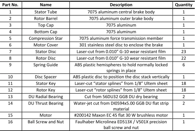
COMPONENT LIST AND DATA SHEETS
MATLAB SIMULINK MODELS
MANUSCRIPT II: DESIGN AND SIMULATION OF A JOINT-COUPLED ORTHOSIS FOR
Joint-Coupled Controlled-Brake Orthosis (JCO)
- The JCO Gait Sequence
- Joint Coupling Design
- Wafer Disc Brakes
- Ankle Support
- Mass and Inertia
The purpose of the joint coupling is to provide hip flexion necessary to generate forward leg movement, which is otherwise challenging due to the inaccessibility of the deep hip flexors via surface stimulation. Since the knee joints should fail in a locked state, as previously mentioned, the knee brakes are thus of the normally locked type. Since the hip brakes are primarily used for lane control and are characterized by relatively low duty cycle operation, the hip brakes are of the normally unlocked type.
The end result is a proportional brake that provides a significantly higher torque-to-weight ratio than a state-of-the-art magnetic particle brake.
Gait Control and Simulation
- Walker Model
- Orthosis Model
- Control Algorithm
- S1 : State 1
- S2 : State 2
- S3 : State 3
- S4 : State 4
- Simulation Results
In the horizontal direction, the interaction between foot and floor is determined by Coulomb friction, where the coefficient of friction is assumed to be 0.3. The shoulder force in the frontal plane is modeled as a spring and damper with an equilibrium point in the vertical orientation, stabilizing the trunk in the frontal plane (i.e., preventing “falls” in that plane). In the proposed system, two controllers are active at the same time, namely the JCO controller (i.e. braking and electrical stimulation) and the user controller, which controls the interaction with the walker via the arms (i.e. shoulder forces and torques).
As indicated in the figure, the duration of electrical stimulation (stage 3) is small compared to the total cycle.
Preliminary Experiments
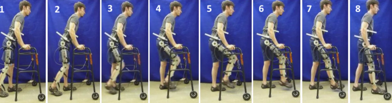
Note that the user starts from idle and remains idle for the first second of the simulation. The first experiment (see Figure D-9) involved placing the healthy subject in a position so that the foot wearing the orthosis was behind and ready to initiate a step. The spring was loaded and the knee was locked in the extended position using a quick connect pin.
This causes the knee to extend and thereby relieves the joint, allowing the hip to extend as well.

Conclusion
The combination of a (one-way) joint coupling and spring spring allows for knee flexion, hip flexion and knee extension, all with surface stimulation of only the quadriceps muscle group of each leg. Schematic representation of the swing phase of JCO gait showing cooperative behavior and sequencing of knee and hip brakes, mechanical bias. This spring is attached to the return end of a bowden cable that is wrapped around the knee brake rotor, creating a torque in the direction of knee flexion as determined by the spring stiffness, balance point, and preload (against hard-stopping the joint).
A simulation of the JCO and the gait controller was performed for a user with height L=1.7m and mass M=65kg.
MANUSCRIPT III: DESIGN OF A JOINT-COUPLED ORTHOSIS FOR FES-AIDED GAIT
Donning and Doffing
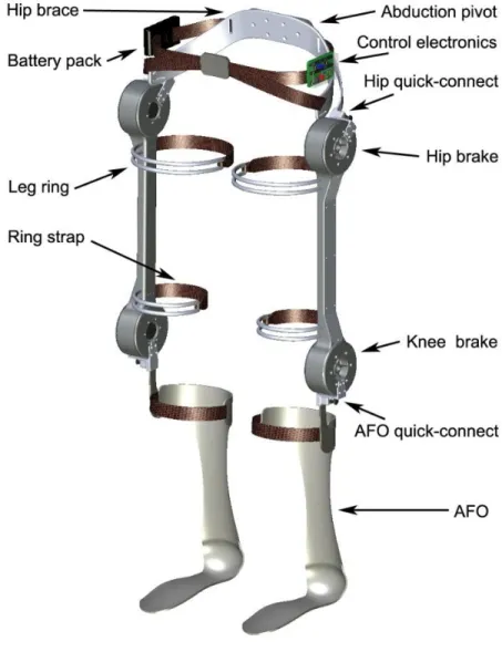
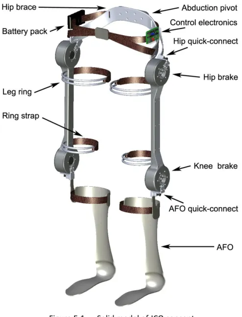
Along with reliability, function and perceived and measurable benefit, one of the most important factors in the acceptance and use of a gait rehabilitation system is ease of use, and foremost among these factors is the user's ability to quickly and easily don and shut down the system. The JCO is designed to be put on (and taken off) quickly, easily and independently while seated. The JCO consists of five component parts, which are carried separately and clipped together by means of structural quick-connect connectors.
Specifically, the JCO is separated into two AFOs, two thigh segments, and a waist belt shown in the figure.
Simulation
A joint-coupled controlled braking orthosis (JCO) is designed as part of a hybrid FES/orthosis system for gait rehabilitation in individuals with spinal cord injury. This device will couple 1) hip-knee flexion in one direction; 2) support hip and knee flexion with a spring support; and 3) contain sensors and modulated friction brakes, which are used in combination with electrical stimulation for the feedback control of joint (and therefore limb) trajectories. Standing and its importance in the treatment of spinal cord injury.” In Proceedings of the RESNA 10th Annual Conference, pp. 8] Triolo RJ and Bogie K, “Lower Extremity Applications of Functional Neuromuscular Stimulation After Spinal Cord Injury,” Topics in Spinal Cord Injury Rehabilitation, vol.
Clinical experience with functional electrical stimulation-assisted walking with Parastep in spinal cord injured patients. Spine., vol.