This Guide provides information on the design, detailing and installation of post-installed rebars. Figure 6 – Applications in bridge rehabilitation with post-installed reinforcing bars 1.3 Compatibility of post-installed reinforcing bars with built-in reinforcement.
How are they designed?
- Design requirements
- Required anchorage length
- Connection detailing
- Design of development and overlap length based on Eurocode2
The post-installed rebar joints assessed according to this technical report shall be designed as straight cast-in-situ reinforcing bars according to Eurocode2, using the values of the design joint resistance fbd for deformed bars as given in the relevant approval. The definition of the connection area in Eurocode2 also applies to post-installed reinforcement.
How are they installed?
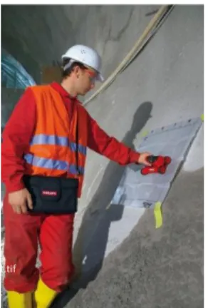
- Location of existing reinforcement and other embedded items
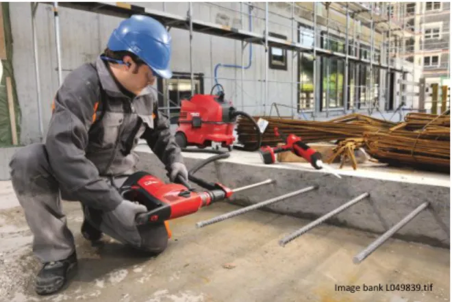
- Roughening the existing concrete surface
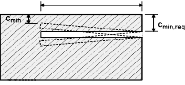
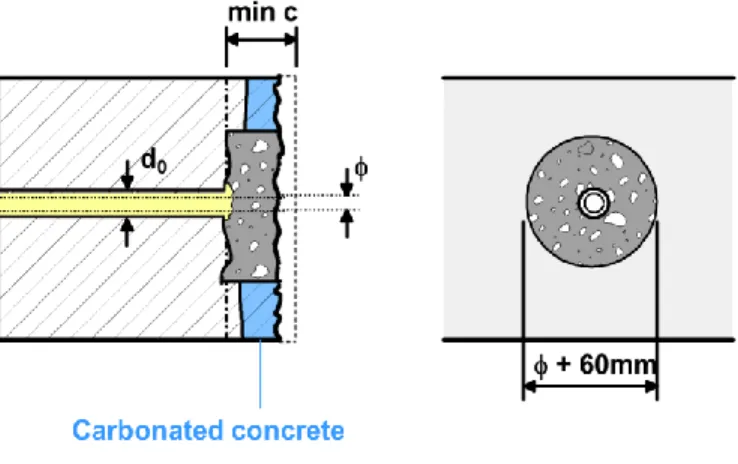
- Installation of post-installed reinforcing bars with small cover
- Hole cleaning
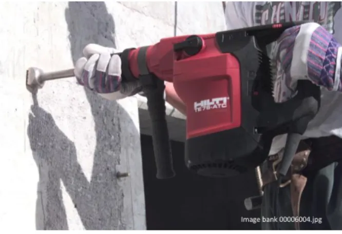
- Bar installation
Qualification of post-installed rebar systems according to EOTA TR 023 [15] includes verification (by means of an accelerated aging test) of the adhesive's corrosion protection. Can the adhesive be injected and the rebar installed within the gel time of the adhesive?
How do I decide which system to use?
System selection considerations
One aspect of system selection that is sometimes overlooked is the absolute volume of adhesive to be placed in the hole. Large diameter and very deep holes may require a larger volume of adhesive than can reasonably be placed even with pneumatic delivery equipment. Furthermore, injection of large amounts of adhesive can result in excessive heat generation due to the exothermic nature of polymerization.
Development of design data 1 Background
Establishment of required system performance (qualification)
The suitability of an adhesive system for post-installation reinforcing bar applications depends on many factors. Systems that may be suitable for anchorage applications will not necessarily meet the requirements for safe and reliable rebar installations. a) b). The ability of the adhesive to develop the required bond strength from the concrete strength class C20/25 to C50/60;.
The sensitivity of the bond resistance to hole cleaning, freezing and thawing conditions, concrete temperature extremes in service, installation orientation and alkalinity/sulfur exposure;. The ability of the system to successfully perform long bar installations (up to 60 bar diameters) without significant voids in the adhesive around the post-installed reinforcing bar;. Although it is generally the case that modern structural-grade adhesives are capable of developing bond strengths greater than those exhibited by cast-in reinforcement, the effects of workplace installation conditions, temperature and other factors included in the assessment can is, bonding reduces material resistance.
![Figure 31 lists the full range of tests required to qualify adhesive anchor systems for post- post-installed reinforcing bar applications as provided in TR023 [15] which can be summarized as:](https://thumb-ap.123doks.com/thumbv2/123dok/10672584.0/29.918.276.754.437.1013/figure-required-adhesive-installed-reinforcing-applications-provided-summarized.webp)
Design concepts
Establishing the required bar anchorage length
Overview of Eurocode2 [5] anchorage length provisions for straight reinforcing bars The Eurocode2 [5] concept of anchorage length is based on the attainable average bond
The design anchorage length lbd is calculated from the basic required anchorage length lb,rqd. Ast = the cross-sectional area of the smallest transverse reinforcement along the design anchorage length lbd (mm2). With the increase in side steel, the concrete's ductility (its ability to sustain large permanent changes in shape without breaking) increases.
5 = takes transverse pressure into account while 5=1-0.04p ≥ 0.7 where p is the transverse pressure along the length of the anchorage (active confinement). The confining pressure applied to laterally prestress the concrete member before loading exerts an initial volumetric stress due to. The design weld length lo is also calculated based on the required base anchorage length lb,rqd.
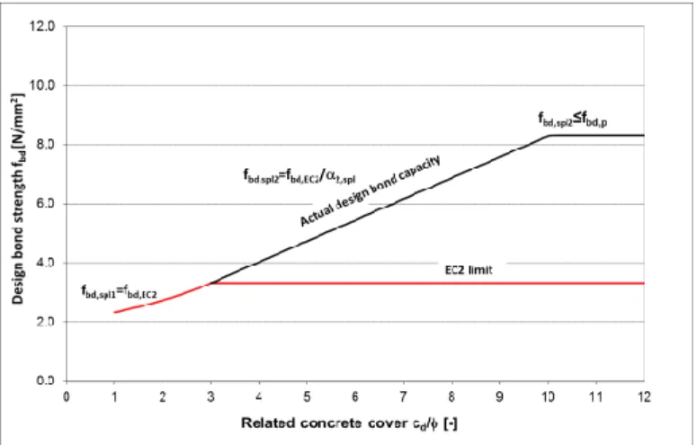
6 =1.5 if all bars are split in the same area (ie the joint is not staggered) which is usually the case with post-installed joint. Hilti anchor adhesives can generate bond stresses that far exceed this limit which is represented by the "actual design bond capacity" line plotted below.
Alternative approaches to establishing bar embedment: Hilti Rebar design method The anchorage length provisions of the Eurocode2 [5] are predicated on the assumption that
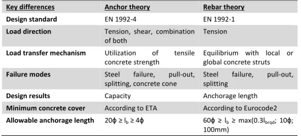
- Design of post-installed reinforcing bars using Hilti Rebar design method Eurocode2 [5]/ETA [15] design method for post-installed reinforcing bars has two main
- Use of confinement to increase bond efficiency (Hilti splitting design)
Even if the spliced retrofit rebar had infinite joint strength values, the joint would fail by pulling out the cast rebar. Therefore, the use of the bond strength values of the type of mortar used, as followed by the Hilti Rebar design method, is limited by the bonded cast rebar embedded using the bond strength values given in Eurocode2 [5]. The result is that the anchorage length of the retrofitted rebar determines the overall anchorage length of the system connection.
Using the Hilti Rebar design method, the anchorage length of retrofitted rebar can be reduced to the anchorage length of cast-in-place rebar. 2 – within its limit – results in a maximum reduction in anchorage length of approximately 43% when the concrete cover is greater than 3. The reduction of the anchor length can also be explained by the increase of the strength of the joint by max.
Eurocode2 [5]Figure 33 shows a typical fbd curve of the design bond strength as a function of the respective concrete cover, shown for concrete class C20/25 and for reinforcing bars with a diameter not exceeding 32 mm. In this figure, the equivalent design joint stresses according to Eurocode2 [5] (red line) and those resulting from the definition of 2 and 2' described above are plotted as a function of the related concrete cover (actual design joint capacity). ).
Design examples
- Design of end support of a simply supported slab according to Eurocode2 Requirement
- Design of splice on support according to Eurocode 2
- Design of end support of a simply supported slab according to HIT Rebar Design Method
- Design of splice on support according to HIT Rebar Design Method
Installation by wet diamond core drilling: Hilti HIT-RE 500 is a suitable adhesive (see technical data), but if wet diamond core drilling is used for installation, the minimum anchorage length according to Eurocode2 must be multiplied by 1.5 (ETA 09-0295 , section 4.3 .3). Installation by wet diamond core drilling: Hilti HIT RE-500 V3 is a suitable adhesive (see technical data), but if wet diamond core drilling is used for installation, the minimum anchorage is .. lbd checks → anchorage length lbd is linst = 255 mm in drilled holes with diamond core also .. lbd, lower lbd, upper cmin3). Specification: Provide post-installed rebar to size, spacing and anchorage length as specified on construction documents.
Note: When using the Hilti rebar design, the minimum anchorage length is determined by lb,min= 120 mm = ribbon. In the same design example, according to the Eurocode2, the design anchorage length is checked with lbd= 162 mm = ribbon. When using the Hilti rebar design, the minimum anchorage length is controlled by lb,min= 110 mm = ribbon.
In the same design example that follows the EC2, the design anchor length is governed by lbd= 255mm = linst. Therefore, the design according to Hilti Rebar design method will result in the same anchor length as if Eurocode 2 was followed.
Strut-and-tie models
Requirement: Provide retrofitted rebar for a new balcony extension on an existing concrete structure as shown below, using the Hilti rebar construction concept. As described in section 6.3.1, the Hilti reinforcement construction concept is not advantageous in case of overlap. In modeling braces and ties, the complex state of internal forces is idealized as a truss.
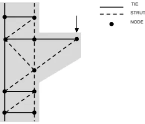
The compression (struts) and tension (tie) members are defined in the region by the user. The brace and tie model, chosen among all, should result in small plastic deformations and economical reinforcement layout. Most post-installed rebar problems can be expressed with some variant of a C-C-T node, as shown in Error.
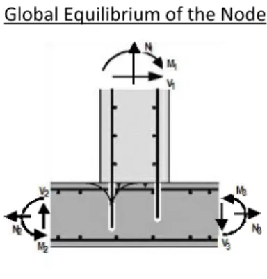
NOTE: A detailed description of the strut-and-splice modeling of a post-installed rebar connection in a column-foundation connection subject to overturning moments is described in Kupfer, et al. Hamad, B., et al., “Evaluation of Bond Strength of glued-in or post-installed reinforcement", ACI Structural Journal V.
Strut-and-tie model for frame nodes (Hilti frame node concept)
The load on the wall (Figure 40b) results in a tensile force in the reinforcement on the left (red arrow) and a compressive force on the right (green arrow). Thus, the compressive stress is not concentrated on the outside of the wall, but is distributed over a large part of the interface, leading to a reduced inner lever arm in the wall section (z1R). Drilling longer than linst,max can cause the concrete cover to crumble due to the impact energy and should therefore be avoided.
The value of the lever arm within the node z0 is therefore smaller than the value of the lever arm of the sheet z2. If the supplied steel area As0,prov is greater than or equal to the required one As0,rqd, the reinforcement of the existing part is sufficient. The smaller the value of the embedment of the post-installed vertical bar, the higher the moment resistance of the plate in the node area is reduced compared to a node with hook bar.
Loads and thermal loads on the panel do not lead to horizontal cracks; therefore, the tensile force can be attributed to the tensile capacity of the concrete. On the safe side, the maximum splitting stress was taken as that caused by the concentrated load C0 in the middle of the anchorage zone.
Design of a moment resisting connection according to HIT Rebar Design Method
On the left side of the anchorage zone, the compression force is continued by means of additional columns in the tension and compression zones of region B of the slab where the balance of horizontal forces is given. The vertical components of these columns are obtained from the elastic stresses in the concrete. Normally there is no vertical reinforcement in the slab to take the tension force.
It has been shown that the incidence of shear stress maxsp can be calculated as. If the calculated maximum shear stress is smaller than the tensile strength of the concrete, then the concrete can absorb the shear forces without any additional shear reinforcement.
What else do I need to know?
- Cracked concrete vs. uncracked concrete
- Additional factors influencing the bond strength
- Fire
- Corrosion
- Design Programme PROFIS Rebar
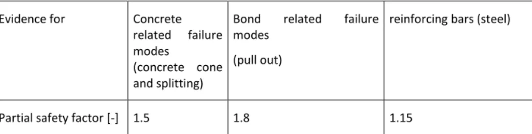
FSd,vet Design value of the anchor force for the rolling load model for fatigue (N) NRd Design resistance for static load of the anchorage (bond and concrete) (N). The bar ETA of the related product reports the reduction factor to be applied to the bond strength as a function of temperature. In the fire condition "parallel", the only decisive parameters are the clear distance from the fire-exposed concrete surface to the circumference of the bar ("clear concrete cover c") and the specific fire duration.
Use of the system is limited to new construction or structures undergoing major repair work. The design study must be carried out at the same time as the reinforcement of the original structure is tested. The loads applied to the reinforcements taking into account the acceleration are the responsibility of the design office.
For concrete containing chlorides, the corrosion behavior of the system corresponds to that of cast-in reinforcement. The report summarizes the sequence of steps and parameters/factors/formulas used to calculate the design solution.
![Figure 8 – Application range of post-installed rebar by EOTA TR023 [15]](https://thumb-ap.123doks.com/thumbv2/123dok/10672584.0/9.918.300.806.403.1040/figure-application-range-post-installed-rebar-eota-tr023.webp)