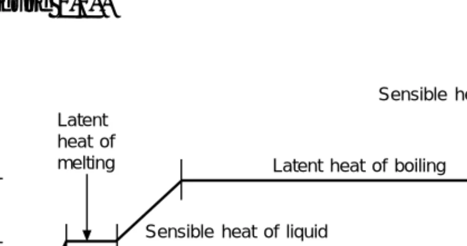
16 Refrigeration in the food industry – meat and fish 188 17 Refrigeration for the dairy, brewery and soft drinks. At a pressure below the three-point pressure, the solid can change directly to a gas (sublimation) and the gas can change directly to a solid, as in the formation of carbon dioxide snow from the released gas.
General gas laws
Between these two limits, if the pressure of the liquid is higher than its boiling point, it will remain a liquid and will be subcooled below saturation, but if the temperature is higher than saturation, it will be a gas and superheated. Example 1.6 What is the volume of 5 kg of an ideal gas with a specific gas constant of 287 J/(kg K), at a pressure of one standard atmosphere and at 25 °C.
Dalton’s law
This mode of heat transfer is very complex and depends first on whether the fluid flow is 'natural', i.e. what is the logarithmic mean temperature change and what is the heat transfer if there is an area of 420 m2 and the transmissivity thermal is 110 W/(m2 K).
Transient heat flow
An exception to this is the effect of solar radiation when considered as a cooling load, such as the air conditioning of a building exposed to sunlight. At the wavelength of sunlight, the absorbance figures vary and calculations for such loads use table factors for the heating effect of sunlight.
Two-phase heat transfer
In this case, the water vapor must diffuse through the air, and the rate of mass transfer will also depend on the concentration of the vapor in the air. In the air-water vapor mixture, the rate of mass transfer is approximately proportional to the rate of heat transfer at the boundary, which simplifies the predictions of the operation of air conditioning coils [1, 5, 9].
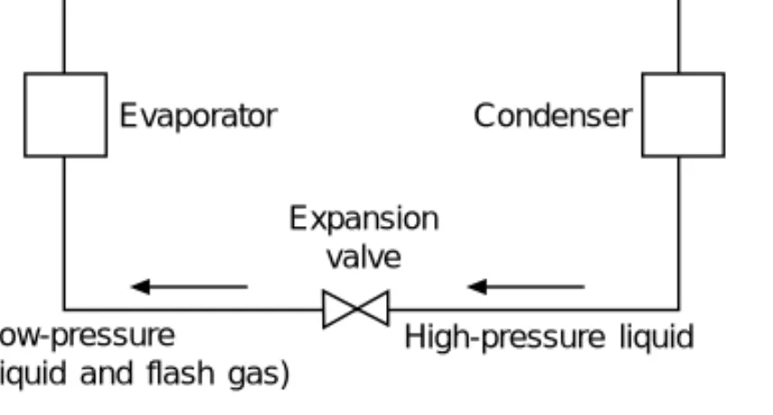
Basic vapour compression cycle
The total cooling effect will be the heat transferred to the working fluid in the boiling or evaporating vessel, i.e. the volume of the working fluid increases therefore in the valve with this amount of heated gas and gives it its name, expansion valve.
Coefficient of performance
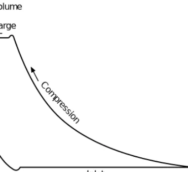
A more informative diagram is the pressure-enthalpy graph, which shows the liquid and vapor states of the fluid (Figure 2.6). The pressure-enthalpy diagram can be a direct measure of the energy transferred during the process.
Heat exchanger size
In an operating circuit, the vapor leaving the evaporator will likely be slightly superheated and the liquid leaving the condenser will be subcooled. The final temperature at the end of compression depends on the operating limits and the refrigerant.
Volumetric efficiency
High-pressure gas remaining in this space at the end of the discharge stroke must be expanded again to the suction inlet pressure before a new charge of gas can be sucked in. This loss of useful stroke will increase with the suction to discharge absolute pressure ratio and compressor efficiency will decrease.
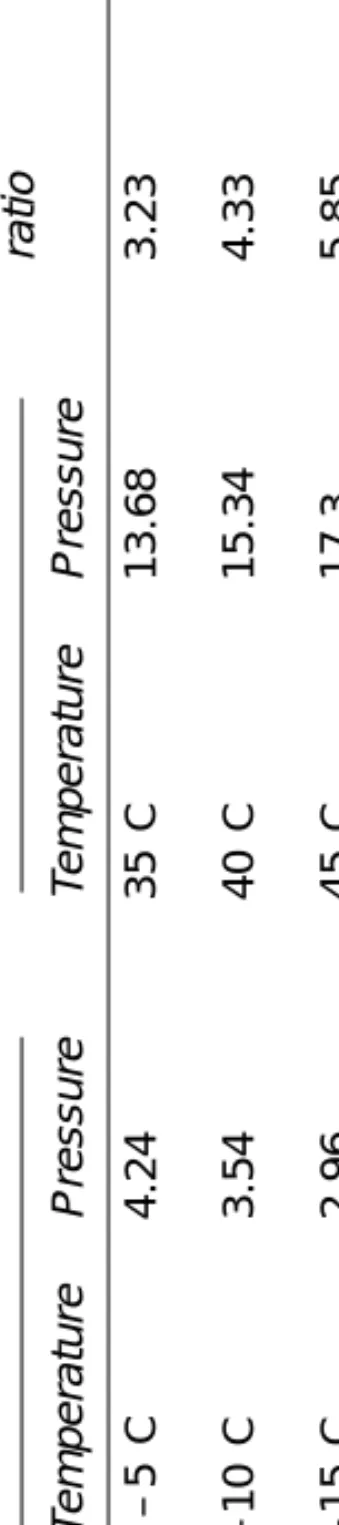
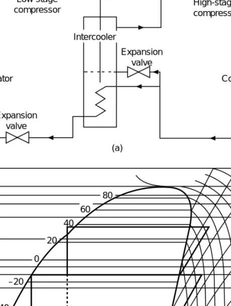
Multistage cycles
The cascade cycle has two separate cooling systems, one acting as a condenser for the other (see Figure 2.10). The Mollier diagrams for compound and cascade systems (Figures 2.9 and 2.10) indicate the enthalpy change per kilogram of circulated refrigerant, but it must be remembered that the mass flows are different for the low and high stages.
Refrigerants for vapour compression cycles The requirements for the working fluid are as follows
No single working fluid has all of these properties and a great many different chemicals have been used over the years.
Total loss refrigerants
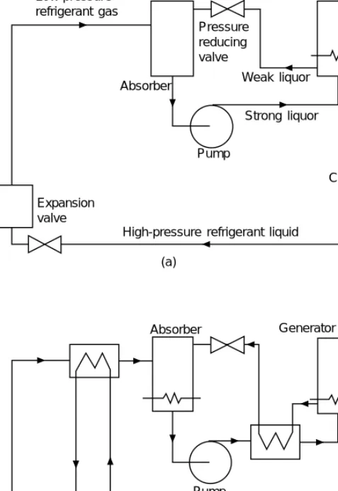
Absorption cycle
The power to the beverage pump will usually be electrical, but the heat energy for the generator can be any form of low grade energy such as oil, gas, hot water or steam. The absorption system can be used to advantage where there is an inexpensive low-grade heat source or where there are severe limitations on available electrical power.
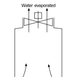
Steam ejector system
Solar radiation can also be used.) The overall energy used is greater than with the compression cycle, so the COP (coefficient of performance) is lower.
Air cycle
Thermoelectric cooling
Background
Ideal properties for a refrigerant
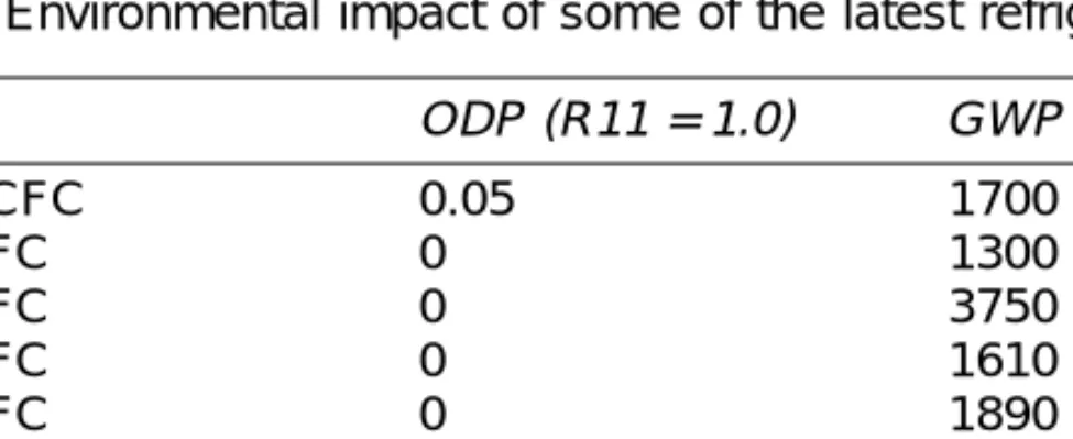
Ozone depletion potential
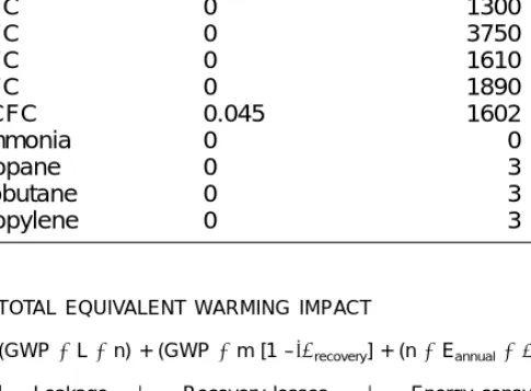
Global warming potential (GWP)
This term shows the overall impact on the global warming effect and includes refrigerant leakage, refrigerant recovery losses and energy consumption. The smaller the amount of energy required to produce each kW of cooling, the smaller the effect on global warming.
Ammonia and the hydrocarbons
One thing that is certain is that the largest element of TEWI is energy consumption, which contributes to the emission of CO2 into the atmosphere. Therefore, the choice of refrigerant is related to the efficiency of the refrigerant and the efficiency of the cooling system.
Refrigerant blends
Hydrocarbons such as propane and butane are being successfully used as replacements and new refrigerants for R12 systems. However, there is a market for their use in closed refrigeration systems such as domestic refrigeration and unitary air conditioners.
Lubricants
The safety aspects of ammonia installations are well documented and there is reason to expect an increase in the use of ammonia as a refrigerant. The moisture in the air is absorbed by the oil and leads to contamination of both the refrigerant and the oil.
Health and safety
General
4 compressors. Figure 4.2 and also Chapter 2, for theoretical and practical cycles on the Mollier chart and for volumetric efficiency).
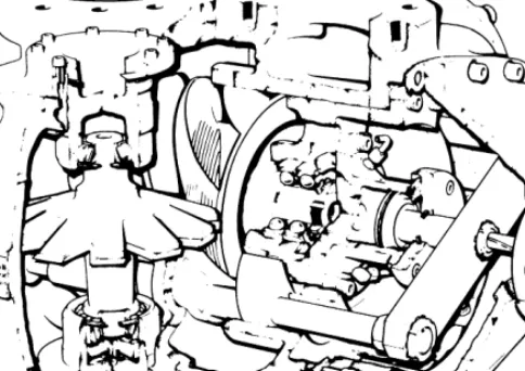
Multicylinder compressors
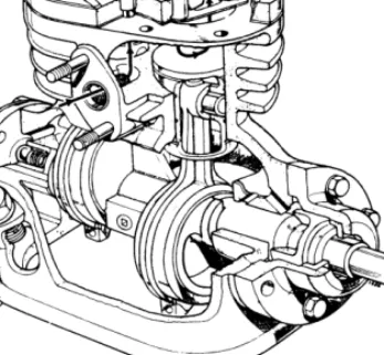
The first commercial reciprocating compressors were built in the middle of the last century, and evolved from the steam engines, which were the prime movers. Compressors for small systems will be simpler, with two, three or four cylinders (see Figure 4.5).
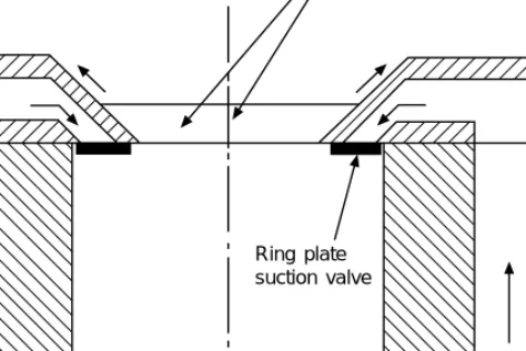
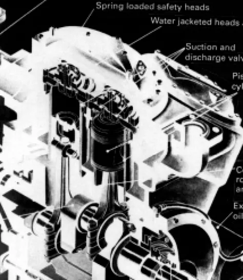
Valves
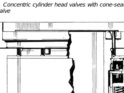
This construction provides a large number of common parts - pistons, connecting rods, loose liners and valves - throughout a range of compressors, and such parts can be replaced if worn or damaged without removing the compressor body from its installation. An alternative valve design uses a conical discharge valve in the center of the cylinder head, with an annular plate suction valve surrounding it.
Capacity reduction
In this way, a multi-cylinder engine (see Figure 4.10) can have any number of its cylinders unloaded for capacity reduction and will start unloading in addition until the build-up of oil pump pressure depresses the valve lifters. The compressor speed can be reduced by two-speed electric motors or by electronic variation of the motor speed, up to a lower limit determined by the built-in lubrication system.
Cooling
Many high-speed industrial machines are still powered by steam turbines, and this allows for speed control within the limits of the motive power.
Strainers. Lubrication
Crankcase heaters
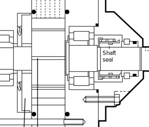
Shaft glands. Motors
Electrical protection and safety devices must take this into account and power factor correction must be provided on large motors. The advent of suitable electronic devices has made it possible to obtain the mains voltage alternating current.
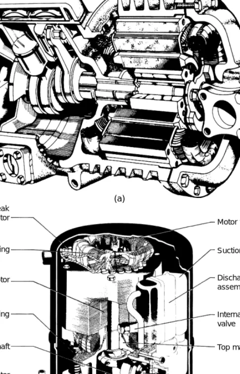
Hermetic drives
The use of a fully hermetic compressor is limited by the amount of cooling by the inlet cold gas, heat loss from the casing and the possible provision of an oil cooler. Failure of the built-in motor will result in decomposition products and serious contamination of the system, which must then be thoroughly cleaned.
Sliding and rotary vane compressors
Sliding vane or roller piston compressors have one or two blades which do not rotate but are held by springs against an eccentrically rotating roller. This type has been widely developed for household appliances, packaged air conditioners and similar applications, up to a cooling capacity of 15 kW (see Figure 4.14).
Screw compressors
Gas sealing on these surfaces is performed by injecting a small amount of liquid coolant. Reducing the capacity of the twin-screw compressor is accomplished by a sliding block that covers part of the barrel wall, which allows gas.
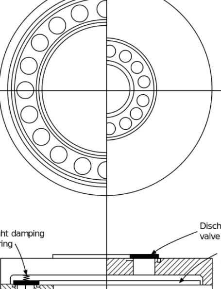
Scroll compressor
The oil separation, cooling and filtering for a twin-screw compressor adds to the complexity of an otherwise simple machine. The dynamic and gas pressure loads are balanced so that they are vibration-free.
Dynamic compressors
With most models, it is possible to reduce the pumping capacity to 10-15% of full flow. The pumping characteristic of a centrifugal machine differs from a positive displacement compressor, as the gas can slip back past the rotor if the output pressure is too high.
Capacity ratings
Oil specifications
Oil separators
In either case, this metering device must be assisted by a solenoid valve to ensure proper shut-off when the compressor stops, as the separator is on discharge and the oil pan on suction. To limit this dilution, a heater is usually installed in the bottom of the separator.
Oil circulation
Automatic drainage and return of the oil from this will have to depend on the different densities, and is very rarely fitted. By bleeding off a proportion of the mixture (about 10% of the mass flow) and separating the oil from this by distillation, the concentration can be kept at an acceptable working limit (see Figure 5.2).
Dry expansion circuit
Removing oil from sumps and low point drains is a periodic manual task and is performed as part of routine maintenance. Evaporators containing a large amount of R.22 will have a greater oil concentration in the upper layers.
Contaminants in oil
Under such conditions, it may not be possible to maintain the minimum velocity to return oil to the compressor, and it will settle in the circuit. Overheating or an electrical fault in the winding of a hermetic or semi-hermetic compressor motor will produce contaminants, including the halogen acids, which can be detected by their pungent smell, litmus paper or other tests [18].
General
Heat to be removed
Providing a separate oil cooler will reduce the condenser load by the amount of heat lost to the oil and removed to the oil cooler. This is of particular note with twin-screw compressors, where a high proportion of the compressor's energy is taken up in the oil.

Air-cooled condensers
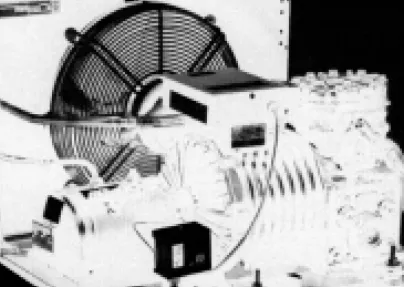
The large airflows required, the power to move them and the resulting noise levels are factors that limit the use of air-cooled condensers. Given the high material costs for air-cooled condensers Figure 6.2 Air-cooled condenser (courtesy of Techni-Coils Ltd).
Water-cooled condensers
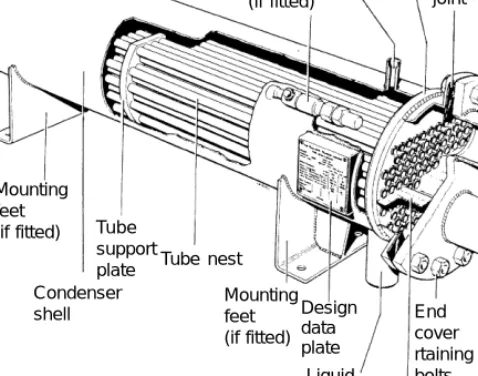
They will also be used in desert areas where the supply of cooling water is unreliable. When the mass flow of water is unrestricted (sea, lake, river or cooling tower), the temperature rise through the condenser can be kept up to 5 K, as this will reduce the MTD ln with a cost reduction in head pressure only for larger water pumps and pipes. if equipped) Tube support plate Condenser shell.
Cooling towers
Evaporative condensers
We will see that the mass flows of water and air through the cooling tower are approximately equal. The cooling tower water dispersion seal is made of treated wood or corrugated plastic sheet.

Water treatment
Example 6.6 The hardness of water in Coventry is given as a maximum of 560 ppm (parts per million) and the water treatment can allow a solids concentration of up to 1200 ppm. All these methods ensure the maximum required drain rate at any time of the year, and this also applies to water wastage under light loads.
Rating and sizing of condensers
The user must be aware of the essential nature of the discharge, as in dry weather it often happens that misguided persons close the drain to "conserve water." This is a rough calculation, based on the direct cost of capital rather than interest rates, and must be analyzed in terms of the overall economics of the plant.
Condenser maintenance
Such dirt can be trapped in a fine water filter, but is more commonly allowed to settle to the bottom of the tank and must be flushed out once or twice a year, depending on the severity of local contamination. Where heavy pollution is expected, it is good practice to provide a deeper tank than usual, the pump suction coming well from the bottom, and tanks 3 m deep are in use.
Condenser fittings
Where plant safety is vital, the tank is divided into two parts, which can be cleaned alternately. Manufacturers shall be aware of the requirements of this BS and related Standards, and proprietary products shall be equipped accordingly.
Other forms of condenser
Those under 85 liters but with an internal diameter greater than 76 mm may have a fusible plug to relieve fire pressure.
Winter operation
This method is particularly useful in residential areas where the higher noise level will be tolerated during the day when the condensed air is warmest, but a lower fan speed can be used at night. A set pressure bypass valve can be fitted across the condenser so that hot gas will pass directly to the receiver in cooler weather.
Receivers
Sufficient refrigerant must be available for this without starving the rest of the circuit (see Chapter 9). The water-cooled condensers, cooling towers and evaporative condensers described in 6.4, 6.5 and 6.6 all use water at a temperature which will promote the growth of the bacteria Legionella pneumophila.
General
Flow pattern and function
Air cooling evaporators
In all but very small radiators, there will be fans to blow the air over the coil. To allow this, fins will be vertical and the airflow horizontal, with a drain pan underneath.
Liquid cooling evaporators
In this way, the shell-and-tube type operates a flooded evaporator (see Figure 7.3) and has oil drain pans if ammonia is used, or a mixture exhaust system if the refrigerant is one of the halocarbons. Evaporators for this service are arranged in the form of a hollow drum (see Figure 7.1b) surrounded by the refrigerant and with internal rotating blades that scrape off the product as it thickens, providing a clean surface to the flow of product and the cold rush stick to the outlet.
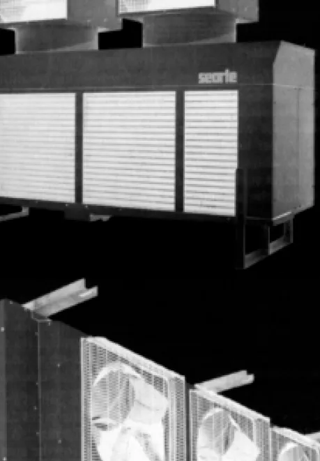
Plate evaporators
Some liquids, such as vegetable fats and ice cream mixes, increase in viscosity significantly as they cool, sticking to the surface of the heat exchanger.
Defrosting
This method can be used for cold rooms, packaged air conditioners, etc., where the service period may be interrupted. Heat storage capsules can be built into the circuit to provide a limited heat reserve for a small installation.
Condensate pumps
Where the ambient air is always at +4°C or higher, it will be sufficient to stop the refrigerant for a period and let the frost melt (as in the household refrigerator with automatic defrosting). In each of these cases, measures must be taken to remove cold refrigerant from the coil while defrosting is in progress.
General
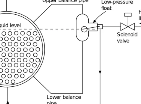
Low-pressure float valves
Low-pressure float switches
Should a float control fail, the level in the shell may rise and liquid may pass into the compressor suction. In such cases, a gas trap or siphon can be formed in the lower balance tube to provide an indirect level in the float chamber.
High-pressure float valve
The low pressure receiver system can be adapted for compound compression and can be equipped with hot gas defrost by reverse gas flow. In both circuits, the low pressure receiver provides the safety container to prevent liquid from entering the compressor.
Thermostatic level control
In this system, the low-pressure receiver circuit, liquid is drained from the condenser through the high-pressure float, but the final stage of the pressure drop occurs in a secondary expansion valve after the hot liquid has passed through coils inside the receiver. In this way, heat is available to boil off excess liquid leaving the evaporator (see Figure 8.4).
Expansion valves for dry expansion circuits
Such valves should be installed so that the test tube is the coldest part (see Figure 8.7). The slope of the T – p curve is not constant, so a fixed spring pressure will result in greater superheating at a higher operating temperature range.

External equalizer
The continuous pursuit of the thermostatic expansion valve means that the surface of the evaporator has an irregular refrigerant supply with a consequent minor loss of heat transfer efficiency. It is likely that this valve will be replaced by the electronic expansion valve for many systems.
Thermostatic liquid level control
Electronic expansion valve
Valves on small systems can sometimes be seen to fully close and fully open. Electronic expansion valves are now widely used on small automatic systems, mainly as a refrigerant flow control device (evaporator or condenser) in an integrated control circuit.
Thermal electric expansion valve
Capillary tube restrictor
General
Thermostats
Humidistats
Pressure switches
To stop the compressor under these conditions, a low-pressure switch is usually installed. The compressor continues to run and pumps the evaporator empty until it is stopped by the low pressure switch.
Oil safety
Pressure gauges
True oil pump pressure can only be indicated by a dual gauge, in which the oil pump discharge rotates an internal circular scale (see Figure 9.3). In this gauge, the suction pressure is read from the circumferential scale and the oil pump pressure by observing the position of the needle relative to the internal scale of the disc.
Solenoid valves
Back pressure regulation valves
The simplest back pressure control valve is spring loaded, balancing the spring pressure plus atmospheric pressure on one side of a diaphragm or piston against the inlet or evaporator pressure. Over approx. 40mm pipe size, the basic back pressure control valve is used as a pilot to operate a main servo valve.
Suction-to-liquid heat exchangers
Allow two or more evaporators operating at different load temperatures to operate the same compressor. A service gauge is usually located adjacent to the valve or as part of the valve assembly to facilitate adjustment or readjustment.
Condenser pressure regulators
It can be located after the heat exchanger, but then an external equalizer is needed to allow the gas pressure to drop through the exchanger. Where evaporative condensers and water cooling towers have only one fan (or fan drive motor), coarse control can be achieved with an on-off switch.
Capacity reduction injection valves
A safer circuit injects the compressed gas directly after the expansion valve or into the evaporator outlet and before the expansion valve sensor. With this arrangement, the expansion valve will allow additional refrigerant to pass through, and the gas entering the compressor will normally be cool.
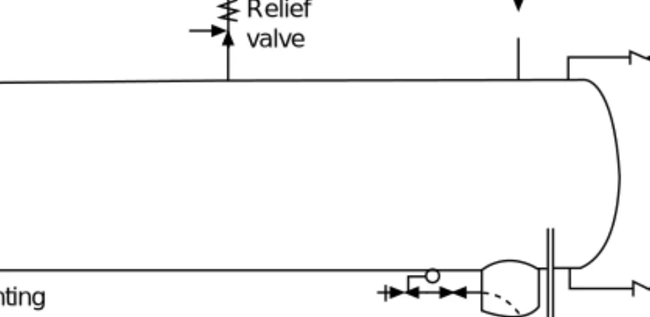
Relief valves
Shut-off valves
Valves should not be installed with the stem down, as any internal dirt will fall into the stem thread. Under low-temperature conditions, ice will form on the spindle and will be forced into the gland if the valve is actuated rapidly.
Strainers
Under such circumstances, the spindle must be well lubricated, or the ice must first be melted.
Strainer-driers
Sight glasses
Charging connection
Auxiliary components
Liquid refrigerant pumps
Suction separators
Liquid separators
Overheat protection
Integrated control systems
Balanced system design
It is likely that a small additional expenditure on some items, especially heat exchangers, will reduce running costs. When maintenance is contracted out, it is important that this is carried out, at least for the warranty period, by the supplier.
Evaporating temperature
Optimum conditions for all products likely to be stored in refrigerated atmospheres will be found in the standard reference books, or may be known from trade practice. Materials not sensitive to dehydration ∆T = 10 K upwards A further consideration may be the possibility of reducing ice build-up on the evaporator, whether in the form of frost on fins or ice on the coils of a liquid cooling coil.
Evaporator
Where near-freezing temperatures are required, it may be an advantage to design with an evaporator temperature high enough to avoid frost or ice—either for safety or to simplify the thawing method.
Compressor
If this threatens to cause problems, a compressor with 50% capacity control can be connected to two equal evaporators, one of which is switched off at half load.
Condenser
Some manufacturers of air-cooled packaged condensing units offer a range of condenser sizes for each compressor, and these should be carefully compared for higher operating costs and lower operating costs. Systems should be allowed to drop to a condensing temperature of 25°C when the refrigerant allows, and some systems can go much lower.
Expansion valve
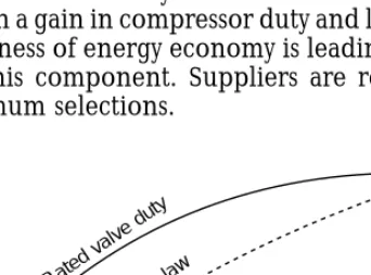
Unless a thermostatic expansion valve is very tightly rated, the system will operate satisfactorily at a lower condensing condition in cool weather, with an increase in compressor duty and lower power input. Under such conditions, the thermostatic expansion valve may be unstable and "hunt" with a slight loss of evaporator efficiency.
Sizing pipe and other components
A greater difficulty arises where the compressor can go down to 33% or 25% capacity and the thermostatic expansion valve is called upon to control a much reduced flow. It is possible to fit two expansion valves in parallel, one for minimum load and both for full load, but this arrangement is not normally necessary.
Recheck components
Materials
Pressure tests for safety
Site-mounted plant shall be pressure tested for safety and leakage after erection (see Section 11.11).
Erection programme
Pipe-joining methods
Where fittings are required, they should be of brass or copper to give a correct capillary joint gap of not more than 0.2 mm, and be joined with solder alloy. Soldering copper tubing will leave a layer of copper oxide inside, which can loosen and move around the circuit.
Piping for oil return
Pipe supports. Valve access
Where these are out of reach, reliance should not be placed on escalators, which may not be there when needed, but permanent access should be provided. Emergency stop valves should not be located in tunnels or canals, as personnel may be subject to additional risk by attempting to operate them.
Instruments
Pressure gauges should always be installed on the discharge side of liquid pumps to check performance and give warning of a possible drop in flow due to dirty strainers.
Rising liquid lines
Vibration
In all cases, the main pipe must be firmly fixed close to the connector so that the latter absorbs all vibrations. In all cases of vibration-damping installation of machines, it must be ensured that other connections – water, electricity, etc.
Cleanliness of piping
For pipes of small bore, these may be ordinary reinforced rubber hoses, suitably fixed at each end. Much of the vibration can be absorbed by ordinary piping up to 50mm or 65mm nominal bore, provided it is long enough and free to move with the compressor.
Site pressure safety tests
On-site hydraulic testing is considered unnecessary due to the extreme difficulty of removing the test fluid afterwards. Other valves in the circuit must be open or closed as needed to achieve the test pressure.
Evacuation
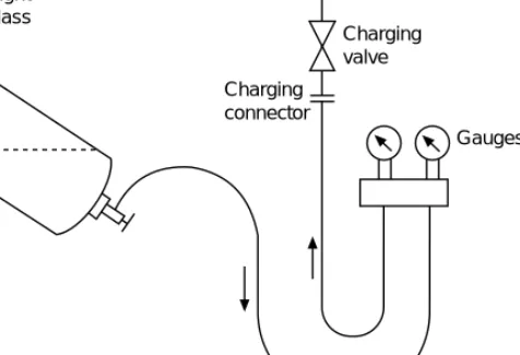
Charging with refrigerant
Increasing the cylinder pressure in this way avoids the use of the throttle valve and the charging process is much faster. In the absence of any firm guidance from the supplier, the crankcase should be topped up gradually during normal running, until it is level with the center of the sight glass under operating conditions.
Insulation
Small packages will have the load marked on the nameplate and should be carefully loaded to this weight, which will be critical. This material has a vapor-tight outer skin, but must be sealed at all joints and edges.
Water circuits
Non-condensible gases
Example 11.2 A system containing R.22 is cooled to an ambient temperature of 20°C and the condenser gauge then indicates 10.5 bar. Ammonia has a much lower molecular mass and the ratio by weight in this example would have been only 3.8 kg of ammonia lost.
Automatic gas purgers
The condensed refrigerant is returned to the condenser and any gas remaining in the vessel will not condense and can be vented from an inverted bucket trap. The water will absorb the ammonia and any bubbles seen rising to the surface will be other gases.
Distributed cooling
Liquid chillers
The main control thermostat will relieve the compressor when the water temperature approaches a lower safe limit, to keep the water as cold as possible without risk of freeze damage. In both, the goal is to improve heat transfer so that the surface in contact with the water will never be cold enough for layers of ice to accumulate.
Baudelot coolers and ice bank coils
Most packaged water chillers are large enough to have capacity control devices in the compressor. If water below 5°C is required, the approach to freezing point poses a significant risk of ice formation and possible damage to the evaporator.
Ice manufacture
This type of water cooler can be used without ice formation, or ice can build up intentionally (see below). Water coolers of these two types are not usually made as a separate package with their condensing unit, due to the bulk of the system and subsequent installation difficulties.
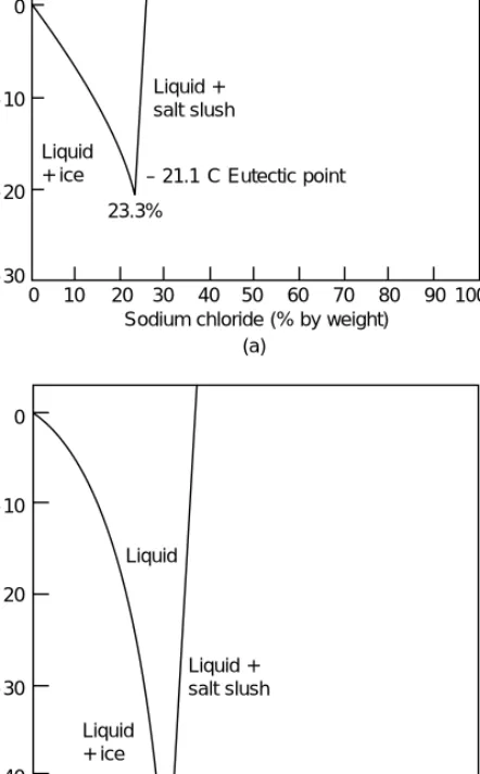
Brines
Physical properties
In salt brines, water can be considered as a heat transfer medium, since the specific heat capacity of the salt content is low (see Figure 12.3). The concentration of the solute has a great influence on the viscosity of the liquid and thus on the surface convection resistance to the heat flow.
Brine circuits
The fluid has a low viscosity and good heat transfer, but is now little used due to its toxicity and fire hazard at high concentrations.
Corrosion
Thermal storage by frozen brines and ice
This system has the advantage of avoiding the corrosion effects of salt brine and can be used at almost any required storage temperature, depending on the eutectic temperature of the mixture inside the capsules. Where cold water is to be used at a higher temperature, such as in air conditioning, the circuit will require three-way mixing valves.
General
Condensing units
Example 13.1 In the curves for an air-cooled condenser, shown in Figure 13.3, what is the cooling capacity at an evaporating temperature of –25°C and with air on the condenser at 25°C. In the table of nominal values in Table 13.1, what is the cooling capacity for a water-cooled condensing unit at evaporation of –20°C, with water on the condenser of 25°C. b) Water-cooled (courtesy of APV Baker Ltd).
One-piece packages
Air cooling, air cooling Air cooling, water cooling Liquid cooling, air cooled Liquid cooling, water cooling. The installation of a packaged unit is more critical than a separate unit as all the components are together and a trade-off may have to be made between the convenience of having the unit close to the load and the difficulty of getting condenser air or water, emitting additional noise or creating new safety considerations.
Split packages
Evaporator units
Application data
Testing of packaged units
Mobile application units
Other packages
Principles of cooling for preservation
Pre-storage treatment
Pre-cooling
A lot of pre-cooling can be achieved by leaving products in the ambient air, especially overnight. Wet products can be pre-cooled in chilled water or by adding flake ice.
Freezing
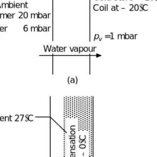
Ice is also used with fish and leafy vegetables to help maintain freshness during storage. Leafy vegetables can be cooled by placing them in a vacuum chamber and thereby evaporating the surface water at low pressure.
Packing and handling
Forklift drivers must be skilled, experienced and safety conscious, as misplacing a pallet on a high stack can pose a serious hazard. Large stores will have a wide loading platform outside at floor level to allow forklifts to maneuver their loads onto vehicles.
Grouping of products
Carcass and side hanging meat pallets will have roughly the same floor area, but will be up to 2m high, with cage sides. They work in well-insulated protective clothing and for short periods within the shift if the temperature in the room is well below 0°C.
Storage conditions
Post-storage operations
Size and shape
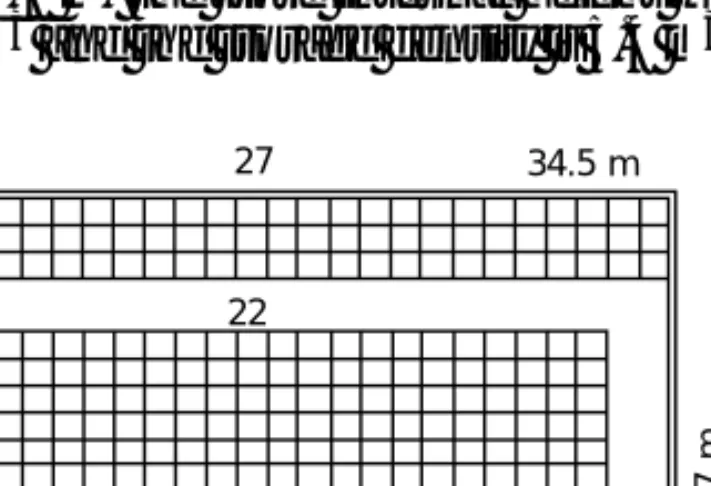
Example 15.2 What would be the volume of this store if the pallets were placed on racks. Example 15.3 What is the floor area of a railed cold room that can hold 500 pieces of beef in the sides.
Insulation
The check-in office will be on the wharf and may have a bridge scale or carcass rail scale. Since there will be some structural interruptions, an allowance of about 5% should be added, making the leakage 3.2 kW.
Vapour barriers
To prevent this deterioration of the insulation, a vapor barrier is required across the hot face. Any small amount of vapor that may enter through defects in the vapor barrier should be encouraged to pass through the inner (cold side) skin of the structure to the coil rather than being trapped in the insulation.
Sectional coldrooms
It follows that, if the vapor barrier is at all suspect, the interior wall covering must be more porous. If it is outside, the vapor barrier should of course be continuous with the main field vapor barrier.
Inbuilt construction
Factory panel systems
The ceiling panels are placed over the tops of the walls and sealed to the warm side of the junction. The outer shell may also be required to support the weight of the evaporators and, in the case of the carcass store, the rails and the product itself.
Floors
Large portal-framed steel beams can provide an inexpensive outer shell, but have a significant amount of roof movement. Panels suspended in this type of structure can be subject to movements that cannot be tolerated in cold storage construction.
Frost-heave
Given a ground temperature of 13°C in the UK, the bottom slab can get as cold as 0°C after many months of shop operation, and any moisture condensed under the floor insulation will freeze and, when it freezes, expand. Over time, this layer of ice under the floor slab, which cannot expand downwards, will lift the floor (frost-lift).
Door and safety exits
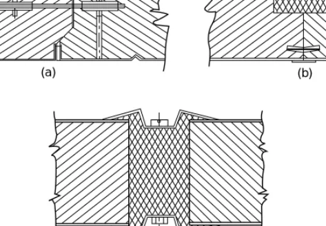
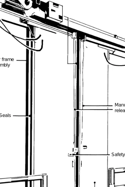
Where a level door threshold is required, the gaskets at the bottom edge will be in the form of two or three flexible blades which simply brush the floor. For most purposes, horizontal sliding doors are used, which close to front seals in the same way as the overlap doors.
Interior finish and fittings
This type of door is common in rooms operating below 0°C and may have heating strips placed on the wall face to prevent any escaping vapor from freezing. Large stores should be equipped with an emergency lighting system, with maintained batteries, to enable exit routes to be clearly seen in the event of a power failure.
Evaporators
Lighting in higher temperature rooms is usually by fluorescent tubes fixed to the ceiling and having switches suitable for the temperature in question. The design of efficient lighting systems deserves careful attention, since all energy put into storage for lighting must be removed again.
Automated cold stores
Security of operation
Before installation, the planned system must be analyzed in terms of possible component failures to ensure that it can work as required. Commissioning run tests should include simulated trials of plant failure, and workers should be made aware of failure drills to keep the plant running.
Meat industry applications
Chilled bone-in meat is stored at approximately 0°C until the point of sale. The humidity is also crucial for fresh meat: too dry and the meat will fall off and discolor, too moist and slime will form on the surface.
Boned, boxed and processed meats
Meat can be frozen on the bone, but this is not a very convenient form for packaging and handling. Freezing can be caused by blowing cold air, and the rate of cooling will depend on the thickness of the board (see [1–7]) and the insulating effect of the box or cover (Figure 16.2).
Pork and bacon
The amount of heat to be removed must be estimated and can be included in the sensible heat capacity in that temperature range. For example, the sensible heat capacity of pork averages 2.5 kJ/(kg K), but for cooling carcasses a figure as high as 3.8 can be used to take this factor into account.
Poultry
A high portion of pork is pickled in brine and smoked, to make ham or bacon.
Fish
If the fish are to be cleaned and processed later, they are frozen whole either by air blasting or, more commonly, in vertical plate freezers (see Figure 7.9b), followed by frozen storage. A limited quantity of fish is frozen by immersing them in cold concentrated sodium chloride brine.
Milk and milk products
![Figure 2.7 Pressure–enthalpy or Mollier diagram (From [10], Courtesy of the Chartered Institution of Building Services Engineers)](https://thumb-ap.123doks.com/thumbv2/123dok/11353847.0/25.892.221.677.658.970/pressure-enthalpy-courtesy-chartered-institution-building-services-engineers.webp)