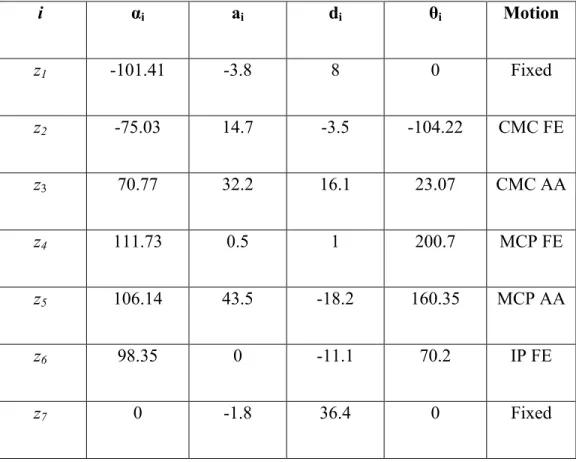
The kinematic model of the thumb has been revised to account for these changes in the rotation of axes (Giurintano, Hollister, Buford, Thompson & Myers, 1995). The DH parameters for the Type II model of the thumb as mentioned are as follows.
Description of Thumb motion
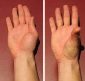
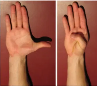
Adduction – Abduction
Flexion-Extension
Range of motion of thumb
We intend to restore the normal range of motion of the thumb through rehabilitation and control of the exoskeleton together with the thumb. It is therefore important to know the normal range of motion of the thumb.
Existing Rehabilitation Devices
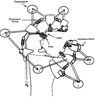
Forces are applied using lightweight pneumatic actuators attached to the tips of the thumb and fingers. Mechanically, it should be able to support the movement of the thumb through its full range of motion.
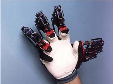
Mechanical Design
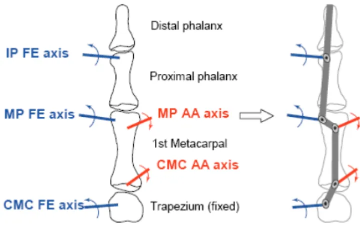
Apart from the movement restrictions, it must also be lightweight so that the patient undergoing rehabilitation does not feel uncomfortable or tire easily due to the device's own weight. An important design aspect for the exoskeleton is the ability to independently control the various joints of the thumb. The thumb has five DOFs and so for each joint of the thumb there is a corresponding joint on the exoskeleton, which maps its movement to the thumb.
Another important aspect of the design is that it should be adjustable and include a wide range of thumbs for rehabilitation purposes. The five actuated joints independently control the flexion/extension movement of the CMC, MCP and the IP joints and the adduction/abduction movement of the CMC and the MCP joint.
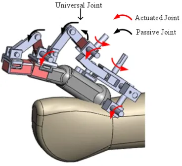
Design of Attachment
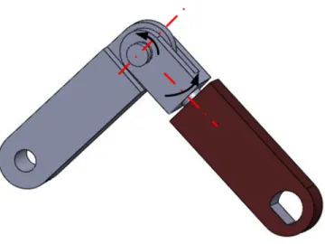
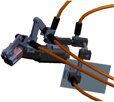
Five active joints are shown by red arrows in Figure 7, two passive joints are in the universal joint, and the third is between the joints connecting the proximal and distal phalanx. As can be seen in Figure 9, the mounting module consists of a base plate that is attached to a fiberglass cast that is worn over the arm. Three screws pass through the steel plate and can be screwed in to attach the exoskeleton to the metacarpal segment.
Plastic tips with flat ends are attached to the screws; these plastic components communicate with the patient's metacarpal segment. Also the underside of all attachment points of the exoskeleton is padded with foam to ensure a firm and comfortable grip of the exoskeleton on the thumb.
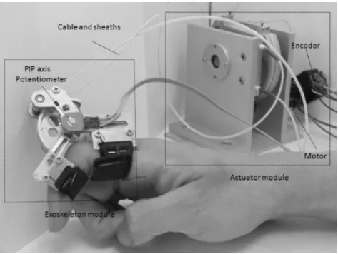
Transmission
The advantage of such a design is that it reduces the number of constraint equations of constraints by one. Similarly, only two constraint equations (x and y) need to be considered when considering a 3D system, and the constraint in the z direction is automatically satisfied. This reduction in force only works for the first contact point on the metacarpal bone.
For the remaining two attachment points, the constraint equations had to be solved for all three directions. So we end up with eight equations, which need to be solved for eight unknowns.
DH parameters for exoskeleton
For example, if two members are moving in a plane with their axes of rotation aligned with each other, and if we want to write the constraint equation for the end tip, instead of writing the position equations for both links, for the x and y directions, we can simply we solve the equations to satisfy one of the coordinates and the other is automatically filled. The chapter generally describes the forward and reverse kinematics routines followed by an open-loop control scheme for the thumb-exoskeleton system. In an open-loop control scheme, the tip of the thumb is made to follow the desired path without violating the constraints (thumb and exoskeleton attachment points) in the system.
Forward Kinematics
Representative models of all four types of thumb kinematic models are also reported. The DH parameters for the type II thumb model are shown in Table 1. The exoskeleton is attached to the thumb in three places, one on each of the three bones.
Using the transformation matrices, the locations of the three points where the exoskeleton and the thumb hinge can be determined. For simulation purposes, SimMechanics models of the thumb and exoskeleton are created using the DH parameters of the thumb and exoskeleton (Tables 1 and 2).
Finding a feasible configuration
To find the eight joint angles of the exoskeleton for a given set of configurations for the thumb, we need to solve the eight equations numerically. But from the physical model of the exoskeleton a reasonably good estimate of the range of motion of the joint angles of the exoskeleton can be found. The above problem of finding a feasible set of joint angles of the exoskeleton can be formulated as a constrained optimization problem.
Also, the same points can be expressed as a function of the joint angles of the thumb, as mentioned earlier. The above actions provide the required joint angles for the exoskeleton, which are within the achievable joint range of motion of the exoskeleton.
Inverse Kinematics
Another MatLab routine fsolve is used to numerically solve the above equations with the results of the previous simulation as an initial guess for the fsolve routine. If the results are not satisfactory, both operations are repeated until the solutions converge. In most simulations, a good initial approximation allows convergence in about eight iterations.
J1a and J1p are the submatrices corresponding to the active and passive joint angles in the exoskeleton.
Constraints
Since the expressions Fi and Gi (i=1,2,3) represent the same point, equations 18, 19 and 20 represent the constraint equations for our system. The above eight constraints (two constraints in the x and y directions for X1 and three in each of the Cartesian directions for X2 and X3) can be written in condensed form as Thus, equation (30) provides the relationship between the passive and active velocities of the exoskeleton joints, and similarly, equation (31) provides the relationship between the angular velocities of the thumb joints and the active velocities of the exoskeleton joints.
Open-loop Control
The plot below shows the variation of thumb joint angles, exoskeleton active angles and exoskeleton passive angles. The above plots validate the exoskeleton design in the sense that the exoskeleton design allows natural movement of the thumb without any hindrance. In the previous chapter, the coupled motion of the thumb exoskeleton system has been discussed in detail.
In this chapter, we discuss a closed-loop inverse kinematics scheme for the coupled motion of the thumb exoskeleton system. Later, we also solve the redundancy and use the redundancy to limit the movement of the thumb within the natural limits of the movement.
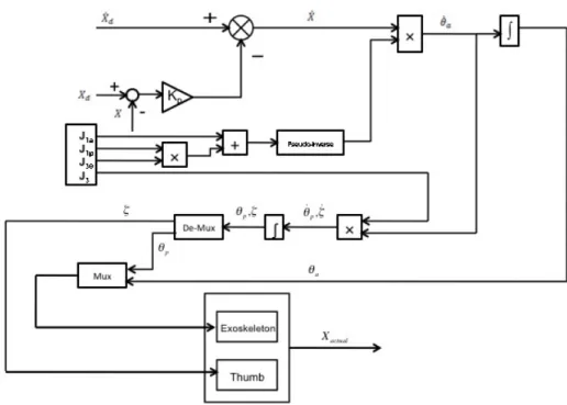
Closed-Loop Inverse Kinematics (CLIK)
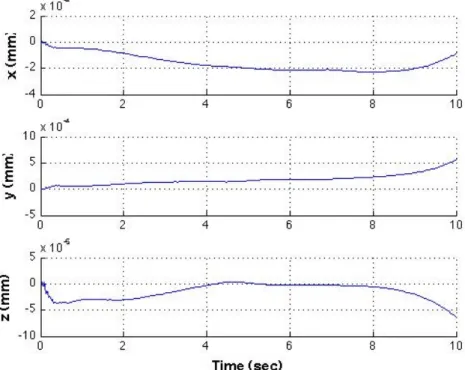
Let's define and as the desired acceleration, velocity, and position of the thumb tip, respectively. To make the above statement more clear, the following plots show the convergence of the trajectory more clearly. The constraints on the three bones of the thumb, the metacarpal, proximal phalanx, and distal phalanx, are also met throughout the course.
In the plots above (Figures 22-24) it can be seen that the errors in the constraints are of the order of 10-4 mm. The graphs below (Figures 25-27) show the variation of the thumb joint angles and the active and passive joint angles of the exoskeleton.
Joint Limit Avoidance for the redundant manipulator
2!where is the Jacobian matrix relating the end-effector velocity to the thumb joint angle velocities. The particular solution of equation (40) is obtained using the pseudoinverse of the matrix and the solution can be written as. In this problem involving the thumb, avoiding the joint boundaries of the thumb while performing natural motion is the main concern.
Thus, the redundant degrees of freedom of the thumb are considered together with the null space solutions to set up a systematic procedure to incorporate common-boundary avoidance. In the current literature (Wang and Li, 2009), the typical choice of null-space joint velocity vector is given by .
Redundancy Resolution at Velocity and Acceleration Levels
The homogeneous function serves as a gradient optimization method, which converges to a local minimum of the cost function, which can be chosen to satisfy the current objective of joint limit avoidance. In the current research, we extended the Closed Loop Inverse Kinematics (CLIK) algorithm to include joint limits in the manipulator. In contrast to velocity-level redundancy resolution, while considering acceleration-level redundancy, it is mandatory to consider the objective function of the shape, which depends on both joint velocity and configuration.
A reasonable choice of equation (48) is one that includes separate contributions from joint velocity and thumb configuration. The structure of equation (50) is motivated by the desire to dampen the joint velocities (with K>0) in the Jacobian null space while attempting to optimize the configuration-dependent criterion.
Results
It can be seen that the errors in the desired and actual trajectories converge to zero during the motion. The zero position of the thumb refers to the straight thumb configuration as shown in Figure 5. The upper and lower limits of the joint angles are found by dividing the range over the reference position of the Type II thumb (Santos & Valero-Cuevas, .
It should be noted in Figure 34 that the thumb joint angles are within the range of motion of the thumb, as expected due to the resolution of redundancy at the acceleration level. Figures 35 and 36 show the corresponding active and passive joint angles of the exoskeleton.
Comparison of Motion of thumb with and without the application of Joint Limits
Also, large off-limit movement of the MP AA (metacarpophalangeal adduction/abduction ("4)) joint is observed throughout the trajectory. It should be noted that the thumb tip follows the predefined trajectory closely in both cases as desired. independent of the use of redundancy resolution In this thesis a general framework for mathematical modeling of the thumb and exoskeleton for rehabilitation is discussed.
The thumb model is based on the Denavit-Hartenberg (DH) parameters found in a recent study (Santos & Valero-Cuevas, 2006). The thesis validates the designed exoskeleton for thumb rehabilitation through simulation and applies a kinematic control scheme for the exoskeleton, which actually controls individual thumb joints independently.
Contributions
The current thumb model takes into account all five DOFs of the thumb, in contrast to previous models that only considered three or four degrees of freedom, excluding the adduction/abduction movements at the CMC and/or the MCP joints. But this approach had the problem that the thumb joints exceeded the normal limits of thumb joint movement. Since the thumb is a redundant manipulator with a degree of redundancy two, the above problem was overcome by using the zero-space solution of the inverse kinematics.
Previous studies show redundancy resolution schemes at the velocity level to limit the motion of a redundant manipulator within the joint boundaries, but the redundancy resolution scheme for joint boundary avoidance was extended to the acceleration level in this thesis and successfully implemented.
Future Work