Settlement of a circular footing on sand
Geometry
The stone layer is not included in the model; instead, an appropriate boundary condition is applied at the bottom of the sand layer. To allow for any possible mechanism in the sand and to avoid any influence of the outer boundary, the model as shown in the figure is extended in the horizontal direction to a total radius of 5.0 m.
Case A: Rigid footing
- Create a new project
- Define the soil stratigraphy
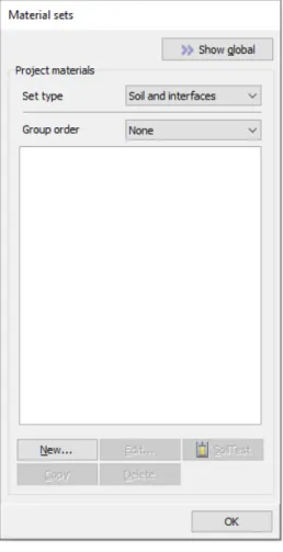
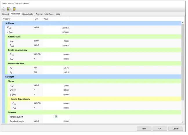
- Create and assign material data sets
- Define the footing
- Generate the mesh
- Define and perform the calculation
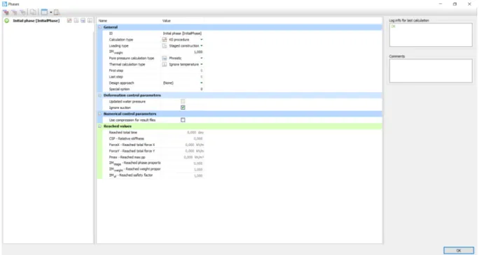
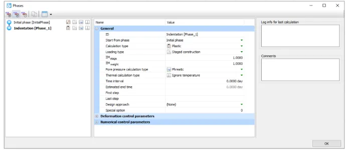
A model of the project in the initial phase is shown in Figure 15 (on page 25). In the ID field of the General section, enter (optionally) an appropriate name for the new phase (for example, Delay).
Case B: Flexible footing
- Modify the geometry
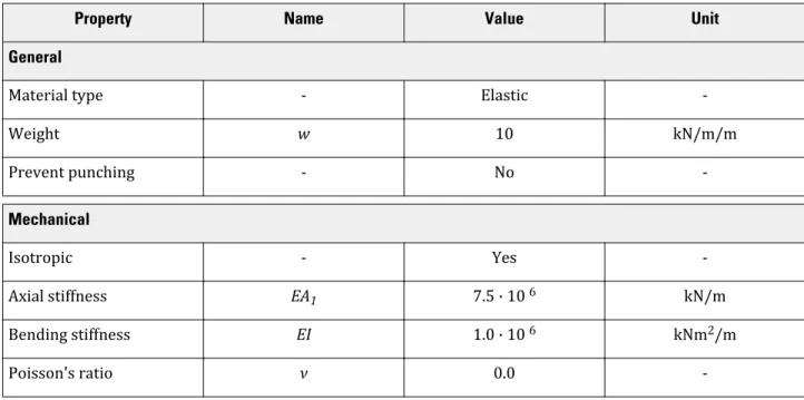
- Add material properties for the footing
- Generate the mesh
- Calculations
- View the calculation results
- Generate a load-displacement curve
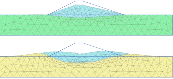
Drained and undrained stability of an embankment
Create new project
Keep the default options for Model (Plane Deformation) and Elements (15-Noded) in the Model tab. Keep the default values for units, constants and the general parameters and click OK to close the Project properties window.
Define the soil stratigraphy
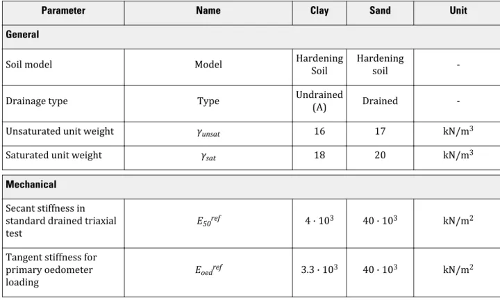
Create and assign material data sets
To create the undrained material set for the clay layer, select the drained material in the Material Set window and click the Duplicate button to duplicate the material set. In the copied material set, change the name and set the Drain Type to Undrained (A).
Create the embankment
Generate the mesh
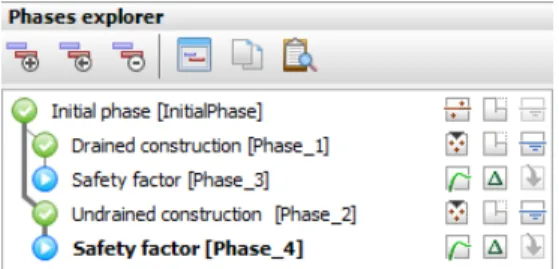
Define and perform the calculation
- Initial phase: Initial conditions
- Phase 1: Embankment construction on drained subsoil
- Phase 2: Embankment construction on undrained subsoil
- Calculate
Right-click on the subsoil and select from the pop-up menu(s) that opens in order the options Soil ( ), Soil ( ), Set material and finally the material representing the undrained subsoil to assign it. Select the subsoil and in the Selection Explorer change the Material under the Soil Object to the material that represents the undrained subsoil.
Results
Click the Refresh button at the top left to close the Output program and save the selected point.
Safety analysis
- Evaluation of safety analysis results
Double-click Chart 1 in the Chart tab (exceeding the second point at (0 -3) vs. time).
Submerged construction of an excavation
Create new project
In the Model tab page keep the default options for Model (Plane Strain}, and Elements (15-Node). The Project Properties window will close and the Soil Mode view will be shown, where the soil stratigraphy can be defined.
Define the soil stratigraphy
Create and assign material data sets
Enter the clay layer properties as listed in Table 4 (on page 54) in the General, Mechanical, and Flow parameter tables. When the Strength option is selected from the Strength drop-down menu, the interface has the same strength properties as the ground (Rinter = 1.0).
Define the structural elements
- To define the diaphragm wall
- To define the interfaces
- To define the excavation levels
- To define the distributed load
Set the Set Type parameter in the Material Sets window to Anchor and click the New button. In the Selection Explorer, assign a value of -5 kN/m/m to the y-component of the load (qy,start,ref) as shown in Figure 46 (on page 61).
Generate the mesh
Define and perform the calculation
- Initial phase
- Phase 1: External load
- Phase 2: First excavation stage
- Phase 3: Installation of a strut
- Phase 4: Second (submerged) excavation stage
- Phase 5: Third excavation stage
- Execute the calculation
Right-click on the wall in the drawing area and select the Activate option from the context menu. In the drawing area, right-click on the group at the top right and select the Disable option in the menu that appears.
View the calculation results
- Displacements and stresses
- Shear forces and bending moments
Settlements due to tunnel construction [GSE]
Create new project
Keep the default values for units and constants and press OK to close the Project properties window.
Define the soil stratigraphy
- Create and assign material data sets
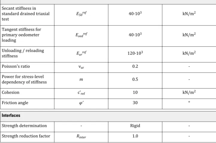
Enter four data sets with the properties listed in Table 7 (on page 75) and Table 8: Material Properties of the Sand Layers (on page 76) and then assign them to the corresponding clusters in the geometry model. Click the Materials button in the Modify Soil Layers window and create the data sets.
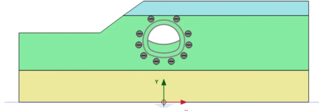
Define the structural elements
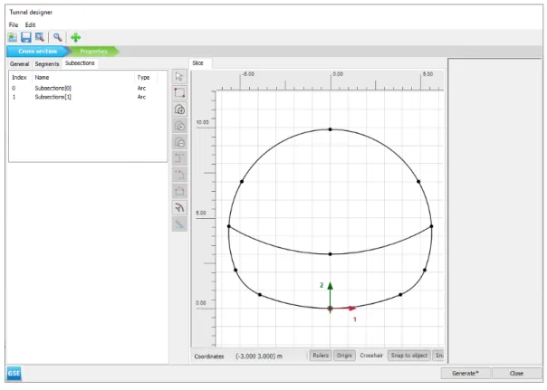
- Define the tunnel
- Define building
Course connections in the lining would be considered (courses can be added after the tunnel design, in the general area of the drawing). Right-click a segment in the display area and select Create Negative Interface from the menu that appears.

Generate the mesh
Create a material set for the foundation piles according to Table 10 (on page 81) and assign it to the foundation piles. Click the View Mesh button to view the mesh as shown in Figure 61 (on page 82).
Define and perform the calculation
- Initial phase
- Phase 1: Building
- Phase 2: TBM
- Phase 3: TBM conicity
- Phase 4: Tail void grouting
- Phase 5: Lining installation
- Execute the calculation
In the Selection Explorer, disable the two soil clusters and set the Water conditions to Dry. The contraction of the tunnel lining itself does not introduce forces into the tunnel lining.
Results
Right-click on the bottom boundary of the model and select the Enable option from the menu that appears.
Excavation of an NATM tunnel [GSE]
Create a new project
In the Model tab, make sure that Model is set to Plane strain and that Elements is set to 15-Noded.
Define the soil stratigraphy
Create and assign material data sets
Create data sets for soil materials according to Table 11 and assign them to the corresponding layers Figure 67 (on page 90) and while assigning values for soft rock layers according to Table 12: Material properties of soft rock layers (on page 91 ), find the analysis for various parameters after expanding the window, one of which is shown in Figure 68 (on page 93). Close the Edit Soil Layers window and proceed to Structures mode to define the structural elements.
Define the tunnel
Click the Select Multiple Objects button and select all the geometric entities in the section. The different segments in the tunnel cross-section can be seen in figure 69 (on page 95).
Generate the mesh
Multiselect the created slabs and assign the Lining material to the selected slabs in the Selection Explorer. Assign negative interfaces to the lines that define the shape of the tunnel (not the excavation levels).
Define and perform the calculation
- Initial phase
- Phase 1: First tunnel excavation (deconfinement)
- Phase 2: First (temporary) lining
- Phase 3: Second tunnel excavation (deconfinement)
- Phase 4: Second (final) lining
- Execute the calculation
With the deactivated cluster still selected, in the Selection Explorer set Deconfinement(1 - β) to 60. With the bottom deactivated cluster still selected, in the Selection Explorer set Deconfinement to 60%.
Results
The optimized parameters are shown in Figure 144 (on page 167) and are also listed in the 'Optimized Value' column in Table 25 (on page 164).
Dry excavation using a tie back wall [ADV]
Create new project
Keep the default values for units and constants and press OK to close the Project Properties window.
Define the soil stratigraphy
Create and assign material data sets
Define three data sets for soil and interfaces with the parameters given in Table 14 (on page 104).
Define the structural elements
- To define the diaphragm wall and interfaces
- To define the excavation levels
- Defining the ground anchor
- To define the distributed load
The embedded beam simulates the sheared portion of the anchor while the joint-to-joint anchor simulates the free length. Set the behavior of the beam embedded in the grout body as shown in Figure 82 (on page 109).
Generate the mesh
Define and perform the calculation
- Initial phase
- Phase 1: Activation of wall and load
- Phase 2: First excavation
- Phase 3: First anchor row
- Phase 4: Second excavation
- Phase 5: Second anchor row
- Phase 6: Final excavation
- Execute the calculation
Click the Create Water Level button on the side toolbar and draw a new phreatic level. Dropped Water Level to rename the water level created in the Flow Conditions mode as shown in Figure 91 (on page 115).
Results
Dry excavation using a tie back wall - ULS [ADV]
Define the geometry
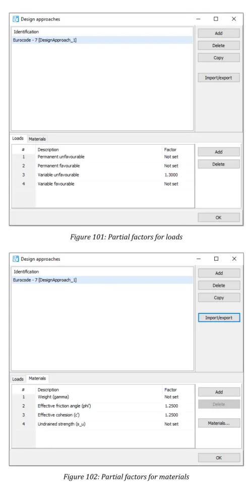
In the lower part of the window, partial factors for loads and materials can be defined, as shown in Figure 102 (on page 121). In the current view, it is possible to assign factors to different soil parameters, as well as to see the effect of these factors on soil parameters.
Define and perform the calculation
- Changes to all phases
- Execute the calculation
Make sure that Phase 7 starts from Phase 1, Phase 8 from Phase 2, Phase 9 from Phase 3 and so on. Select some characteristic points for the curves (for example the connection points of the ground anchors on the diaphragm wall, such as (40 27) and (40 23)).
Results
Construction of a road embankment [ADV]
Create new project
Define the soil stratigraphy
Create and assign material data sets
Create soil material data sets according to Table 20 (on page 128) and assign them to the corresponding layers in the borehole (see Figure 107 (on page 127)).
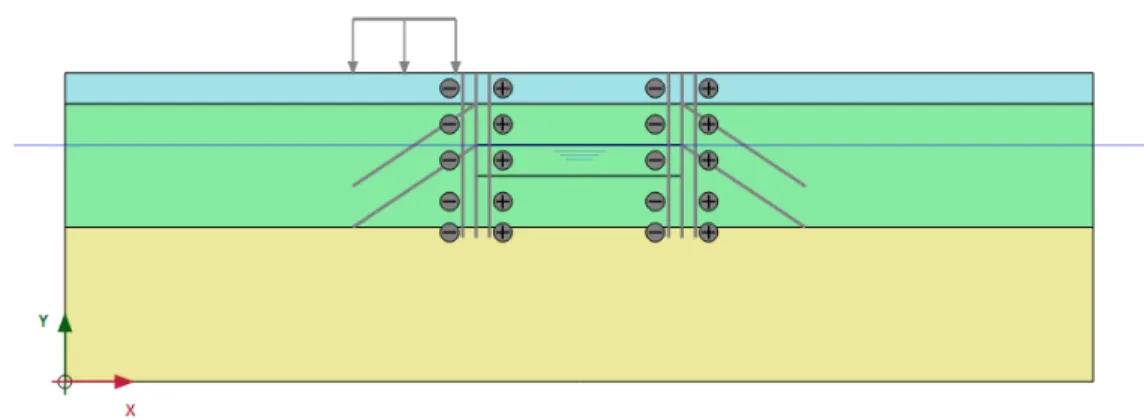
Define the construction
- To define the embankment
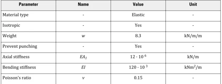
- To define the drains
Note: The initial void ratio (einit) and the change in permeability (ck) should be defined to enable modeling of a change in permeability in a consolidation analysis due to soil compression. The modeling of drainage in a plane deformation model actually involves the use of an equivalent (lateral) permeability in the surrounding soil based on the drainage pattern.
Generate the mesh
Define and perform the calculation
- Initial phase: Initial conditions
- Consolidation analysis
- Safety analysis
- Calculate
In the Stages window, select Consolidation from the Calculation type drop-down menu in the General subtree. During a consolidation analysis, the development over time can be viewed in the upper part of the calculation inspector, as shown in Figure 117 (on page 137).

Results
- Safety analysis results
For the x-axis, select Project from the drop-down menu and select Time from the tree. For the y-axis, select the point in the middle of the soft soil layer (point B) from the drop-down menu.

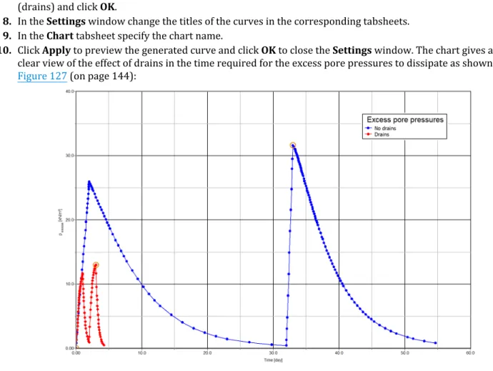
Using drains
A new curve is added to the chart and a new corresponding tab opens in the Settings window. Instead of adding a new curve, the existing curve can be regenerated using the corresponding button in the Curves settings window.
Updated mesh and updated water pressures analysis
In the selection explorer, the wells behavior is set to Extract by default. The cross section results change is displayed in a new window as shown in.
Excavation and dewatering [ADV]
Create and assign material data set
Open the project defined in the Dry Excavation Using Retaining Wall [ADV] tutorial (on page 102).
Define the structural elements
Generate the mesh
Define and perform the calculation
- Phase 6: Dewatering
- Execute the calculation
Results
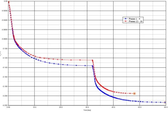
This tutorial illustrates how to calculate the vertical bearing capacity and vertical stiffness of a rigid underwater circular foundation (eg one of the foundations of a jacket structure) exposed to cyclic loading during a storm. The cyclic behavior of the soil is based on the contour diagrams for the Drammen clay (Andersen, Kleven & Heien, 1988 2) assuming that the behavior is.

Create new project
Define the soil stratigraphy
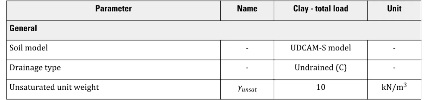
Create and assign material data sets
- Material: Clay - total load
- Material: Clay - cyclic load
- Material: Concrete
Ratio of initial shear modulus to degraded shear strength at failure in triaxial compression. The ratio of the degraded shear strength at failure in the triaxial extension test to the degraded shear strength in the triaxial compression test.
Define the structural elements
- Define the concrete foundation
- Define the interfaces
- Define a vertical load
Make a copy of the Clay - cyclic load material and name it Clay - cyclic load - interface. To calculate the vertical cyclic capacity and stiffness, a vertical load is applied to the top of the foundation.
Generate the mesh
Define and perform the calculation
- Initial phase
- Phase 1: Footing and interface activation
- Phase 2: Cyclic Vertical Bearing capacity and stiffness
- Phase 3: Calculate vertical cyclic stiffness
- Execute the calculation
In the Phases window go to the deformation control parameters subtree and select the Reset displacements to zero and Reset small strain options. Go to the deformation control parameters subtree and select the option Reset displacements to zero and Reset small strain.
Results
In the General subtree, select the Transient groundwater flow option as pore pressure calculation type. In the Model Explorer, set DischargeFunction_1 under Discharge function as shown in Figure 169 (on page 194).
Flow through an embankment [ULT]
Create new project
Define the soil stratigraphy
Create and assign material data set
Define the floor material according to the table above and assign the material data set to the cluster.
Generate the mesh
Select Fine from the Element Distribution drop-down menu and create a mesh. Click the View Mesh button to view the mesh as shown in Figure 153 (on page 179).
Define and perform the calculation
- Initial phase
- Phase 1-Transient ground water flow analysis
- Phase 2-Long term groundwater flow analysis
- Execute the calculation
In the Flow Functions window, select the Harmonic option from the Signal drop-down menu. In the General subtree, select the Initial phase in the Start from phase drop-down list.
Results
Click the Ripping Options button on the bottom toolbar, and the Ripping window appears as shown in Figure 163 (on page 187). For precipitation, select the time-dependent option in the corresponding drop-down menu and assign the defined function.
Potato field moisture content [ULT]
Create new project
Define the soil stratigraphy
Create and assign material data sets
Generate the mesh
Click the View mesh button to view the mesh shown in Figure 166 (on page 190).
Define and perform the calculation
- Initial phase
- Transient phase
- Execute the calculation
In the Phases window, select Flow only as the calculation type in the General subtree. Specify a name for the function and select the Table option from the Signal drop-down menu.
Results
The normal phreatic level on the right side of the dam is 10m below the ground surface. In the initial phase, initial stresses and initial pore water pressures of the dam under normal operating conditions are calculated using Gravity loading.
Stability of dam under rapid drawdown [ULT]
Create new project
Define the soil stratigraphy
Create and assign material data sets
Create data groups by group type Earth and interface according to the information given in Table 30 (on page 197).
Define the dam
Generate the mesh
Define and perform the calculation
- Initial phase: Dam construction & high reservoir
- Phase 1: Rapid drawdown
- Phase 2: Slow drawdown
- Phase 3: Low level
- Phase 4 to 7: Safety analysis
- Execute the calculation
Results
Dynamics analysis of a generator on an elastic foundation [ULT]
Create new project
Define the soil stratigraphy
Create and assign material data sets
Define the structural elements
Generate the mesh
Define and perform the calculation
- Initial phase
- Phase 1: Footing
- Phase 2: Start generator
- Phase 3: Stop generator
- Execute the calculation
- Additional calculation with damping
Results
Pile driving [ULT]
Create new project
Define the soil stratigraphy
Create and assign material data sets
Define the structural elements
- Define the pile
- Define a load
Generate the mesh
Define and perform the calculation
- Initial phase
- Phase 1: Pile activation
- Phase 2: Pile driving
- Phase 3: Fading
- Execute the calculation
Results
Free vibration and earthquake analysis of a building [ULT]
Create new project
Define the soil stratigraphy
Create and assign material data sets
Define the structural elements
- Define the building
- Define the loads
- Create interfaces on the boundary
Generate the mesh
Define and perform the calculation
- Initial phase
- Phase 1: Building
- Phase 2: Excitation
- Phase 4: Earthquake
- Execute the calculation
Results
Thermal expansion of a navigable lock [ULT]
Create new project
Define the soil stratigraphy
Create and assign material data sets
Define the structural elements
Generate the mesh
Define and perform the calculation
- Initial phase
- Phase 1: Construction
- Phase 2: Heating
- Execute the calculation
Results
Freeze pipes in tunnel construction [ULT]
Create new project
Define the soil stratigraphy
Create and assign material data sets
Define the structural elements
Generate the mesh
Define and perform the calculation
- Initial phase
- Phase 1: Transient calculation
- Execute the calculation
Results