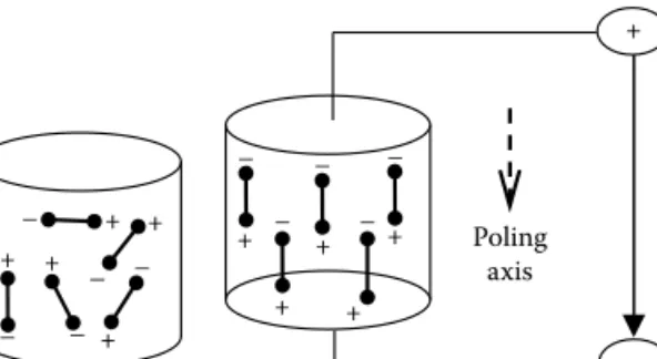
A vibration control of a flexible beam is presented by the implementation of piezoceramic actuators associated with the quantitative feedback theory (QFT) control technique, in which system uncertainties such as non-linear hysteresis behavior of the piezoactuators are treated. Since piezoelectric materials possess anisotropic properties, their mechanical and electrical behavior is dependent on the direction of the external electric field relative to a set of axes fixed in the material.
General Requirements for Control Devices
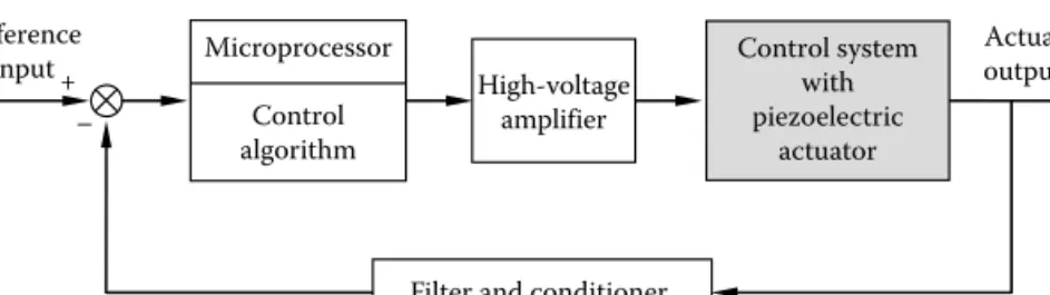
Based on the prescribed specifications, the appropriate smart material actuator or sensor combination is then determined. Most of the currently available sensors, such as the accelerometer, can be adapted to measure the dynamic responses of a control system coupled to piezoelectric actuators.
PID Control
The control value u(t) is changed at a rate proportional to the actuating error signal e(t) using controller I. Using the action of controller I, the steady-state error of the control system can be effectively mitigated or eliminated .
LQ Control
But OS instability can occur when using very high feedback gains of kp. The matrices Q and R determine the relative importance of the error and the control energy consumption.
Sliding Mode Control
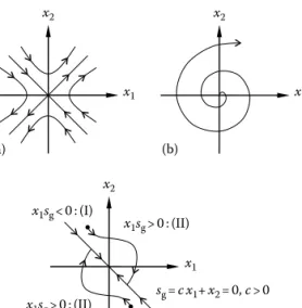
This implies that the initial system response is independent of system parameters on the sliding line (movement in sliding mode). In general, the sliding mode movement can be achieved by satisfying the following so-called sliding mode condition [3]:.
H ∞ Control
In the controller given by equation 2.22, k is the discrete control gain and sgn(·) is a sign function. The H∞ rates also have a physically meaningful interpretation that is the largest possible gain over all unity sinusoidal input frequencies.
![Figure 2.6 shows a loop shaping design procedure (LSDP) using H ∞ synthesis for a left coprime factor perturbed plant given by [5,6]](https://thumb-ap.123doks.com/thumbv2/123dok/10290926.0/25.661.213.439.95.306/figure-shaping-design-procedure-synthesis-coprime-factor-perturbed.webp)
QFT Control
From a plot of the open-loop frequency response G(jω), the values of Lm(M(jω)) and phase α(jω) can be found. The performance specifications consist of limitations on the magnitude of the closed-loop frequency responses.
Inverse Model Control
- Introduction
- Dynamic Modeling
- Controller Formulation
- General Formulation
- Application to the Structure
- Control Results
- Some Final Thoughts
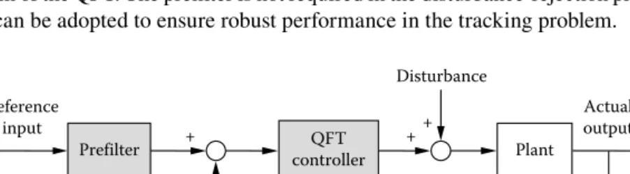
This implies that the control ratio of the closed-loop transfer function can be changed by the prefi lter. Observing position (from fixed) 100 mm. the steady state error for the step reference input of the system.
Vibration Control of Hull Structures
- Introduction
- Dynamic Modeling
- Modal Analysis
- Controller Formulation
- Control Results
- Some Final Thoughts
Piezoelectric Actuator FIGURE 3.13 Geometry of the end-coated hull structure with surface-bonded piezoelectric actuators. The fundamental mode shapes of the end-covered hull structure without piezoelectric actuators are the same, as shown in Figure 3.15.
Vibration Control Using Piezostack Mount
Introduction
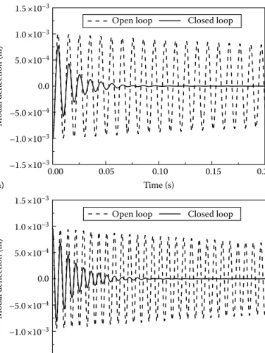
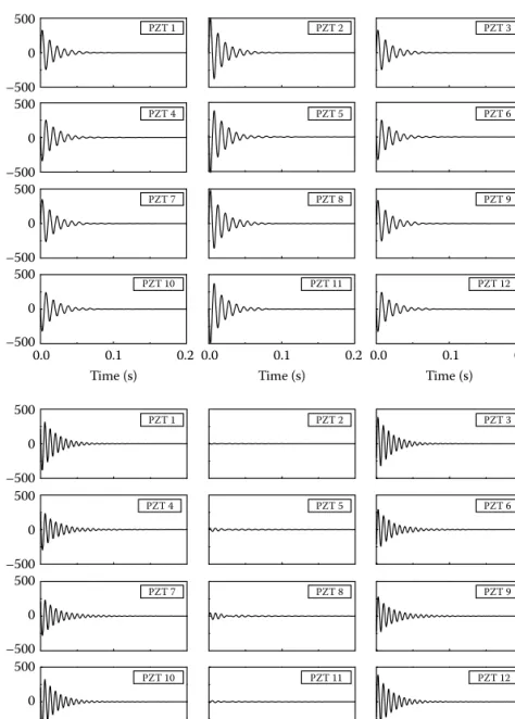
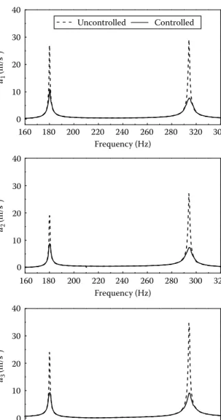
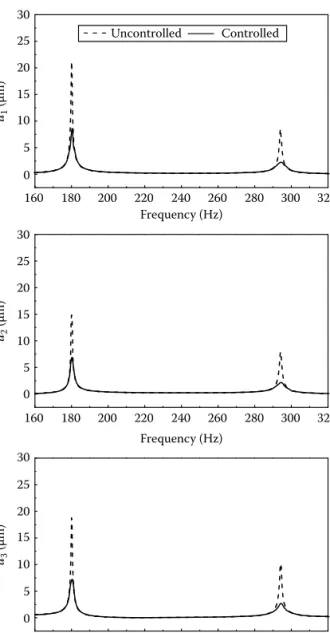
A sliding mode controller is then designed to actively control unwanted vibration responses of the system due to the imposed excitations. The controller is experimentally implemented and vibration control performances such as acceleration and displacement of the beam structure are evaluated and presented in both frequency and time domains.
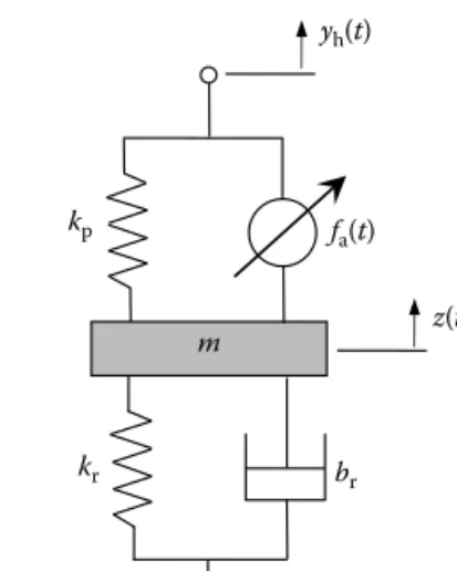
Mount Design
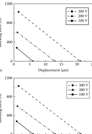
A is the cross-sectional area of the piezoelectric element l and δ(t) is the length and stroke of the piezoelectric actuator kp(= Ac/l) is the spring constant. The piezostack actuator is of the bipolar type and is connected to the rubber mount through the intermediate mass.
System Modeling and Analysis
In the above, qi(t) is the generalized modal coordinate, ϕi(x) is the mode shape function at position x, ωi is the natural frequency of the beam, ζi is the damping ratio of the beam, and Ii is the generalized mass of the i -the mode. Equation 3.38 can thus be rewritten to integrate with the hybrid container model.
Controller Formulation
On the other hand, the weakening of dynamic movement of the intermediate mass implies the control of the transmitted power by the hybrid mount. The sliding mode controller satisfying the existence condition of the sliding mode motion in Equation 3.46 is obtained by.
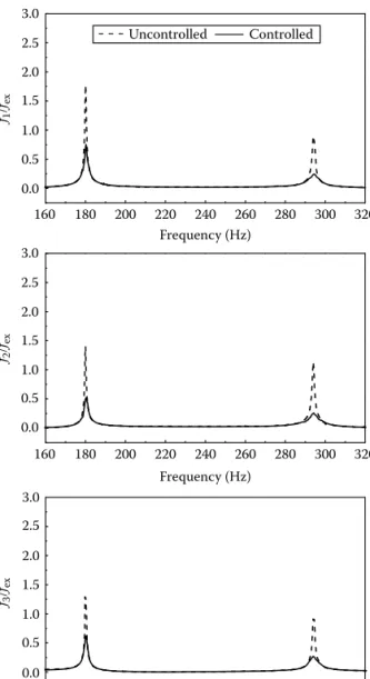
Control Results
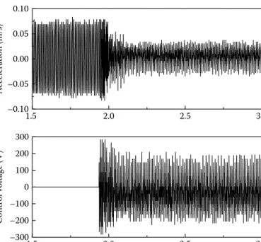
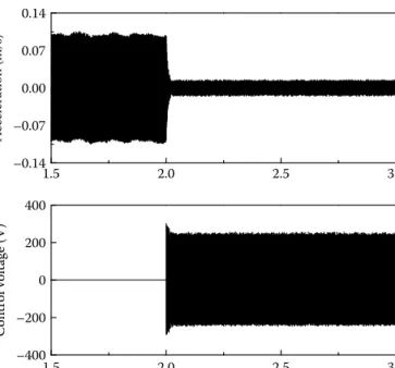
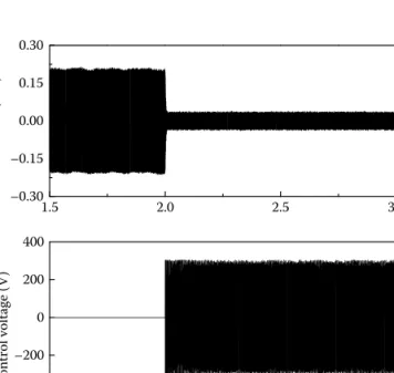
From the remarkable reduction of the force transfer to the base, it can be seen that the imposed vibration of the beam structure has been effectively isolated. One clearly observes significant reductions in the accelerations, displacements and forces transmitted by actuation.
Some Concluding Comments
Numerical modeling of distributed active vibration absorbers (DAVA) for control of plate-radiated noise. Active vibration control of frame structures with smart structures rising piezoelectric actuators (vibration control by control of bending moments of columns).
Introduction
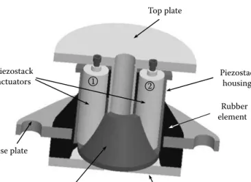
The adopted mount consists of one passive rubber element and two active piezostack actuators with additional mass; we call it "hybrid active carrier". Then, a vibration control system consisting of a hybrid active mount and a supported mass of 100 kg is set up to evaluate the effectiveness of vibration control.
Design and Modeling
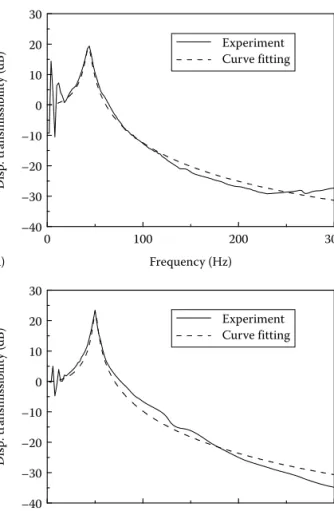
After manufacturing the assembly, dynamic properties of the piezo stacks and the rubber element are experimentally identified. This is possible because the stiffness of the piezo stack is much higher than that of the rubber element.
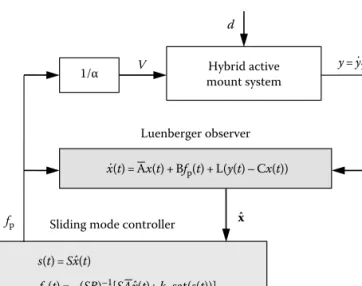
Controller Formulation
It should be noted that the stability of the system is ensured if the observer and the controller are well designed. The observer poles are designed to be fast enough that the estimated states quickly converge to the actual states using the pole placement technique.
Control Results
From the experimental results, it can be seen that when the controller is turned on, the vibration of the mass is attenuated from 0.114 to 0.014 m/s2, or equivalently, −18.4 dB more than in the uncontrolled case. It is noted that the stiffness of the piezo stack is much higher than that of the rubber element.
Some Concluding Comments
At the low frequency, however, the vibration damping is not as good as at high frequencies. In the hybrid active holder, the operating force is mainly generated by the inertia force.
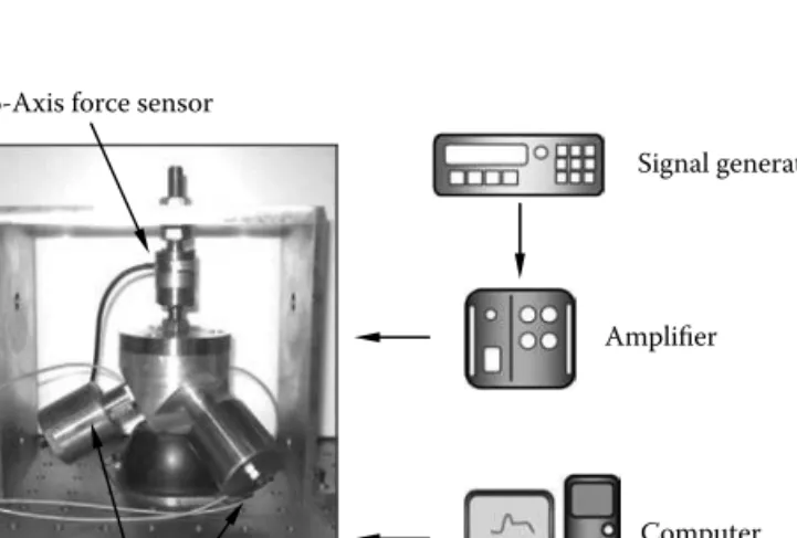
Three-Axis Active Mount
Introduction
The active mounting system consists of the rubber element and the inertia type piezoelectric actuator (piezo actuator for short). The vibration control performance of the 3-axis active holder is verified by computer simulation with significant practical applications.
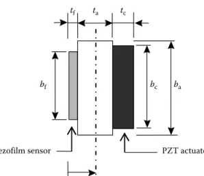
Parameter Identifi cation
- The Rubber Element
- The Piezoelectric Actuator
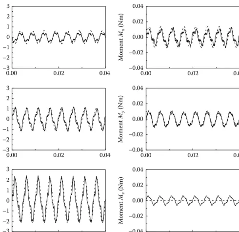
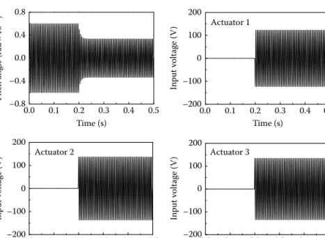
These parameters will be used for the force and moment evaluation of the 3-axis active mount shown in Figure 4.24. It is the inherent characteristic of the inertia type actuator that is very effective for vibration control.
Dynamic Modeling
Br is the distance from the origin {B} to the center of gravity of the rubber and joint. BX and BΩ are the linear and angular displacement, respectively, at the center of gravity of the active holder.
Controller Formulation and Results
From the mechanical model shown in Figure 4.30b, the governing equation of motion of the structural system can be derived as follows: 4.46) where Me and BÎs are the mass and moment of inertia of the structure respectively.
Some Concluding Comments
From the results, it can be ensured that the inertial type of 3-axis piezoelectric beam is very effective for vibration control in the motion of a multi-degree-of-freedom structural system. Active vibration control of frame structures with smart structures using piezoelectric actuators (vibration control by control of column bending moments).
Introduction
Dynamic Modeling
The controller associated with the piezoceramic actuator is designed based on Lyapunov stability. M is the configuration-dependent system mass matrix K is the system stiffness matrix associated with the bond elasticity f is the nonlinear inertial effects (Coriolis force and centrifugal force) z is the generalized coordinate vector.
Controller Formulation
- Sliding Mode Controller
- Constant Amplitude Controller
This satisfies Lyapunov's stability condition and thus guarantees the stability of the distributed system (5.8). In other words, the stability of the flexible manipulator system can be easily violated.
Control Responses
Climbing the tip mass reduces the first natural frequency of the elbow beam from 5.42 to 1.76 Hz. Figure 5.6b shows that a large swing occurs at the top of the elbow joint.
Some Final Thoughts
However, the implemented controllers work very well without oscillations by applying a feedback voltage to the piezoceramic actuators. Favorable tracking control performance in terms of tracking error without unwanted oscillation due to link flexibility was obtained.
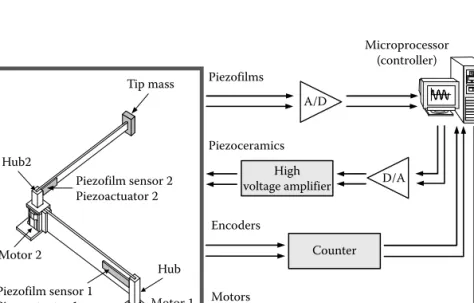
Flexible Gantry Robot
- Introduction
- System Modeling
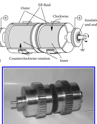
- Bidirectional ER Clutch Actuator
- Modeling of Flexible Gantry Robot
- Controller Formulation
- Control Responses
- Some Final Thoughts
This constant is determined by the geometric and material properties of the flexible arm. The disturbance caused by the acceleration of the moving part affects the flexible arm to be oscillated.
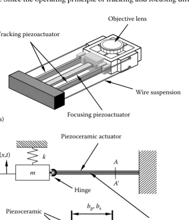
Optical Pickup Device
- Introduction
- Modeling and Mechanism Design
- Controller Formulation
- Control Results
- Some Concluding Comments
The objective lens attached to the tip of the piezoceramic bimorph can be considered as a concentrated mass m. This constant is determined by the geometric and the material properties of the piezoceramic bimorph.
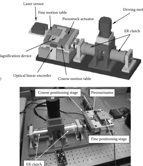
Dual-Servo Stage
Introduction
They designed the disturbance estimator and robust feedback control system to eliminate external disturbances, such as unwanted vibrations on the fine positioning system due to coarse movements of the robot arm. The ER clutch actuator is one of the most potential candidates for coarse motion control in dual-servo systems.
Modeling and Mechanism Design
- Coarse Motion Stage
- Fine Motion Stage
A fine positioning stage consisting of the piezostack actuator and the displacement amplifier has been developed to achieve fast and accurate positioning. Therefore, it can be assumed that the function of the magnifying device cannot affect the gross movement.
Controller Formulation
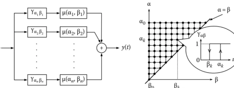
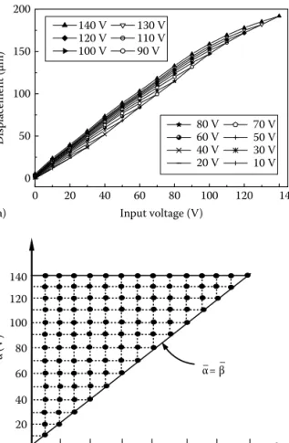
The Preisach model for describing the hysteresis behavior of the piezostack actuator-driven fine positioning stage can be expressed by [28]. It is noted that the reliability of the hysteresis output calculated by the Preisach model is entirely dependent on the accuracy of the experimentally obtained FOD data sets for the Preisach function, Y(αk, βk).
Control Results
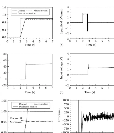
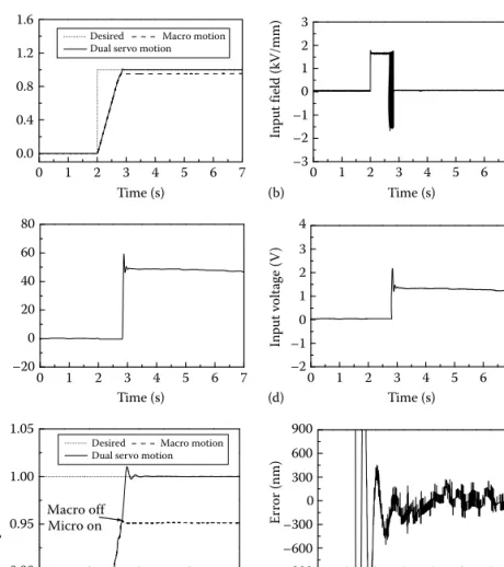
So, it is expected that the control accuracy of the dual servo system can be improved by adopting a high-performance DC drive motor. To investigate the control stability of the dual servo system, a mass of 3 kg is added to the coarse motion stage.
Some Concluding Comments
Development of a high-precision assembly robot with a fine motion mechanism (2nd report) - control of the fine mechanism taking into account the dynamic response and disturbances of the coarse mechanism. Dual servo stage position control with electrorheological fluid coupling and piezostack actuator.
Introduction
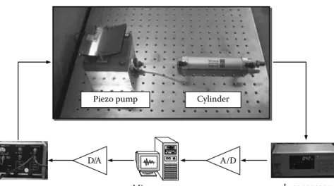
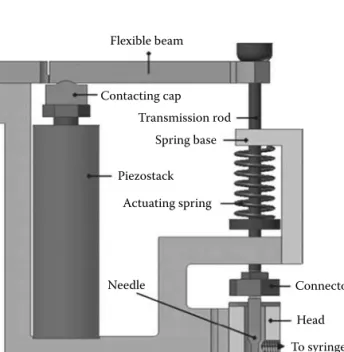
Pump Design and Analysis
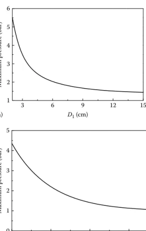
Pcrack is the minimum pressure to open the control valve Cq is the flow rate constant of the control valve. This is, of course, due to the reduction of the volume change in the room.
Controller Formulation
ΔP is the pressure difference between the cylinder pressure from the piezo pump and the external pressure. By considering the cylinder force balance and adding a proportional damping, the governing equation of the cylinder system is derived from.
Control Results
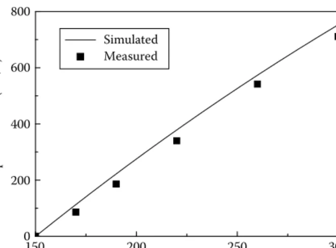
The favorable agreement between simulation and measurement validates the control model of the piezo pump-driven cylinder system. Small tracking errors at the peaks can be caused by non-linear behavior of the diaphragm and cylinder friction.
Some Concluding Comments
The starting position of the cylinder rod is fixed to be 5 mm from the starting position. It has been demonstrated that both the regulation and tracking control performances of the piezo pump-based cylinder system are favorable.
Piezoactuator-Driven Jetting Dispenser
- Introduction
- Mechanism Design
- Dynamic Modeling
- Controller Formulation and Responses
- Some Concluding Comments
- Introduction
- Shunt Circuit Design
- Implementation and Analysis
- Dynamic Characteristics of the
- Admittance Analysis of the CD-ROM
- Shunt Responses
- Some Final Thoughts
The flow rate at the nozzle depends on the speed and position of the needle. Δj is the net deflection of hump j (a positive value of Δj reflects an extension of the spring).
Vibration Control of the HDD Disk-Spindle System
Introduction
Modal Analysis
Shunt Circuit Design
Analysis and Optimization
- Admittance Analysis
- Sensitivity Analysis for Optimal
Implementation and Results
Some Final Thoughts
![FIGURE 3.5 Nominal loop transmission [L o (j ω )]. (From Choi, S.B. et al., ASME J. Dyn](https://thumb-ap.123doks.com/thumbv2/123dok/10290926.0/42.661.128.532.95.428/figure-nominal-loop-transmission-l-choi-asme-dyn.webp)