Keywords
-
Carbon steel electrodes, shielded metal arc welding welding electrodes, covered electrodes, arc welding, filler metal specificationANSI/AWS A5.1-91 An American National Standard Approved by American National Standards Institute February 14,1991
Specification for Carbon Steel Electrodes for Shielded Metal Arc Welding
Supersedes A W S A5.1-81
Prepared by
A W S Committee on Filler Metal
Under the direction of AWS Technical Activities Committee
Approved by AWS Board of Directors
Abstract
This specification establishes the requirements for classification of carbon steel electrodes for shielded metal arc welding. The requirements include mechanical properties of weld metal, weld metal soundness, and usability of electrode. Requirements for chemical composition of the weld metal, moisture content of low hydrogen electrode coverings, standard sizes and lengths, marking, manufacturing, and packaging are also included. A guide to the use of the standard is included in an Appendix.
Optional supplemental requirements include improved toughness and ductility, lower moisture contents, and diffusible hydrogen limits.
A American Welding Society
v
550 N.W. LeJeune Ro.ad, P.O. Box 351040, Miami, FL 33135made part documents that are included in federal or state laws and regulations, or the regulations of other governmental bodies, their provisions carry the full legal authority of the statute. In such cases, any changes in those AWS standards must be approved by the governmental body having statutory jurisdiction before they can become a part of those laws and regulations. In all cases, these standards carry the full legal authority of the contract or other document that invokes the AWS standards. Where this contractual relationship exists, changes in or deviations from requirements of an AWS standard must be by agreement between the con- tracting parties.
International Standard Book Number: 0-87 17 1-349-7 American Welding Society, 550 N.W. LeJeune Road, P. O. Box 351040, Miami, Florida 33135
@ 199 1 by American Welding Society. All rights reserved Printed in the United States of America Note: The primary purpose of AWS is to serve and benefit its members. To this end, AWS provides a forum for the exchange, consideration, and discussion of ideas and proposals that are relevant to the welding indus- try and the consensus of which forms the basis for these standards. By providing such a forum, AWS does not assume any duties to which a user of these standards may be required to adhere. By publishing this standard, the American Welding Society does not insure anyone using the information it contains against any liability arising from that use. Publication of a standard by the American Welding Society does not carry with it any right to make, use, or sell any patented items. Users of the information in this standard should make an independent investigation of the validity of that information for their particular use and the patent status of any item referred to herein.
This standard is subject to revision at any time by the AWS Filler Metal Committee. It must be reviewed every five years and if not revised, it must be either reapproved or withdrawn. Comments (recommendations, additions, or deletions) and any pertinent data that may be of use in improving this standard are requested and should be addressed to AWS Headquarters, Such comments will receive careful consideration by the AWS Filler Metal Committee and the author of the comments will be informed of the committee’s response to the comments. Guests are invited to attend all meetings of the AWS Filler Metal Committee to express their comments verbally. Procedures for appeal of an adverse decision concerning all such comments are provided in the Rules of Operation of the Technical Activities Committee. A copy of these Rules can be obtained from the American Welding Society, 550 N.W. LeJeune Road, P. O. Box 351040, Miami, Florida 33135.
"Advisor
Personnel
AWS Committee on Filler Metal W; L. Wilcox, Chairman
D. J. Kotecki, 1st Vice Chairman D. F. Beb. 2nd Vice Chairman
W; A. Dierschow, Secretary Z . AI-Hillal D. R. Amos J. B. Bolton J. Caprarola, Jr.
R . J. Christofel D. A. DelSignore
R B. Dìckerson H. W Ebert M. F. Godfiey**
J. Gonzalez G. Hallstrom, Jr.
D. C. Helton
W; S. Howes J. P. Hunt G. A. Kurisky R. A. LaFave N. E. Larson A. S. Laurenson G. H. MacShane L. B. Matthew
W ; F. McLaughlin M. T Merlo G. E. Metzger J. W Mortimer L. W ; Mott C. L. Null Y: Ogata J, Payne R . L. Peaslee E. W Pickering L. F. Roberts D. Rozet R K. Salvesen O. W ; Seth R. W; Straiton R . D. Sutton J. W ; Tackett
Scott Paper Company Teledyne McKay Crane Midwest
American Welding Society Liquid Carbonic
Westinghouse Turbine Plant Kennametal
Alloy Rods Corporation General Electric Company Westinghouse Electric Company Aluminum Company of America
Exxon Research and Engineering Company Consultant
The Lincoln Electric Company Nuclear Regulatory Commission Consultant
National Electrical Manufacturers Association Inco Alloys International
Maryland Specialty Wire Elliott Company
Union Carbide Corp.
Consultant
Stoody Deloro Stellite, Incorporated Harley Davidson York, Incorporated Chrysler Corporation
Tri-Mark, Incorporated Wright-Patterson AFB Consultant
Hobart Brothers Company Naval Sea Systems Command Kobe Steel America, Incorporated Schneider Services International Wall Colmonoy Corporation
Combustion Engineering, Incorporated Canadian Welding Bureau
Consultant
American Bureau of Shipping CBI Na-Con, Incorporated Bechtel Group, Incorporated
L-Tec Welding and Cutting Systems Haynes International Incorporated
*Advisor
"Advisor
**
DeceasedW; A. Wiehe F, J. Winsor K. G. Wold T J. Wonder L. J. Christensen"
R. L. Harris*
P. A . Kammer"
R. K. Lee*
L. M. Malik*
S. D. Reynolds, Jr.*
H. S. Sayre*
R. Timerman*
A . E. Wiehe"
Hoskins Manufacturing Company Consultant
Aqua-Chem, Incorporated
Rexham Aerospace and Defense Group Consultant
Southern California Edison Eutectic Corporation Consultant
Consultant
Westinghouse Electric Corporation Consultant
Conarco, S.A.
Consultant
AWS Subcommittee on Carbon and Low Alloy Steel Electrodes and Rods for Shielded Metal Arc and Oxyfuel Gas Welding R. A. LaFave, Chairman
E. W Pickering, Vice Chairman W. A . Diemhow, Secretary Z. Al-Hillal D. F. Betz L. A . Colarossi**
H. W Ebert E. A . Flynn G. L. Franke A . L. Gombach J. Gonzalez D. J. Kotecki G. A . Leclair R.H. Marsh
Y; Ogata M . I? Parekh L. J. Privoznik M. A . Quintana L. F. Roberts D. Rozet P. K. Salvesen O. W; Seth M. S. Sierdzinski R. D. Sutton R. A. Swain K. J. Walsh W: L. Wilcox A . H. Miller"
R. Timerman*
A . E, Wiehe"
Elliott Company
Combustion Engineering, Incorporated American Welding Society
Liquid Carbonic Crane Midwest Consultant
Exxon Research and Engineering Company Sun R and M
David Taylor Research Center Champion Welding Products The Lincoln Electric Company Teledyne McKay
Foster Wheeler Energy Corporation Consultant
Kobe Steel America, Incorporated Hobart Brothers Company
Westinghouse Electric Corporation General Dynamics Corporation Canadian Welding Bureau Consultant
American Bureau of Shipping CBI Na-Con, Incorporated Alloy Rods Corporation
L-Tec Welding and Cutting Systems Welders Supply, Incorporated Trimark, Incorporated
Scott Paper Company DISC
Conarco, S.A.
Consultant
Foreword
(This Foreword is not a part of ANSIIAWS A5.1-9 1 Specfzcation for Carbon Steel Electrodes for Shielded Metal Arc Welding, but is included for information purposes only.)
This specification is the latest revision of the first filler metal specification issued over 50 years ago, The initial 1940 document and the three revisions within the next five years were prepared by a joint committee of the American Society for Testing and Materials and the American Welding Society. However, they were issued with only an ASTM specification designation. The 1948 revision was the first specification issued with the AWS designation appearing on the document. The 1969 revision was the first time that the document was issued without the ASTM designation.
The current document is the eleventh revision of this very popular specification and the fourth prepared exclusively by the AWS Filler Metal Committee. It contains a number of significant revisions from ANSIIAWS A5.1-8 1.
Document Development:
ASTM A233-40T Tentative Specifications for Iron and Steel Arc-Welding Electrodes ASTM A233-42T Tentative Specifications for Iron and Steel Arc-Welding Electrodes ASTM A233-43T Tentative Specifications for Iron and Steel Arc-Welding Electrodes ASTM A233-45T Tentative Specifications for Iron and Steel Arc-Welding Electrodes ASTM A233-48T Tentative Specifications for Mild Steel Arc-Welding Electrodes ASTM A233-55T Tentative Specifications for Mild Steel
AWS A5.1-48T
AWS A5.1-55T Arc-Welding Electrodes
ASTM A233-58T Tentative Specification for Mild Steel AWS A5.1-58T Arc-Welding Electrodes
AWS A5.1-64T Tentative Specification for Mild Steel Covered ASTM A233-64T Arc-Welding Electrodes
AWS A5.1-69 Specification for Mild Steel Covered Arc-Welding ANSI W3.1-1973 Electrodes
ANSUAWS A5.1-78 Specification for Carbon Steel Covered Arc-Welding Electrodes ANSVAWS A5.1-8 1 Specification for Carbon Steel Covered Arc-Welding Electrodes
Comments and suggestions for the improvement of this standard are welcome. They should be sent to the Secretary, Filler Metal Committee, American Welding Society, 550 N.W. LeJeune Road, P. O . Box 351040, Miami, Florida 33 135.
Official interpretations of any of the technical requirements of this standard may be obtained by sending a request, in writing, to the Technical Director, American Welding Society. A formal reply will be issued after it has been reviewed by the appropriate personnel following established procedures.
Page No
. Table of Contents
Pessonnel
. . .
Foreword
. . .
ListofTables
. . .
ListofFiguses
. . .
1 . Scope
. . .
Past A . General Requirements
. . .
2
.
Classification. . .
3
.
Acceptance. . .
4
.
Certification. . .
5
.
Units of Measure and Rounding-Off Procedure. . .
Part B . Tests. Procedures. and Requirements
. . .
6
.
SummaryofTests. . .
7
.
Retest. . .
8
.
Weld Test Assemblies. . .
9
.
Chemical Analysis. . .
1 O
.
Radiographic Test. . .
11
.
TensionTest. . .
12
.
BendTest. . .
13
.
ImpactTest. . .
14
.
Fillet Weld Test. . .
15
.
MoistureTest. . .
16
.
Absorbed Moisture Test. . .
17
.
Diffusible Hydrogen Test. . .
111
...
V v111
...
ix 1 1 1 1 1 1 2 2 3 3 8 8 13 17 20 20 24 27 28
AUS A 5 - 1 0 0 1 1 7 6 8 0 7 8 4 2 b 5 9 1 ' W 7
I
Part C - Manl&acture, IdentiJication, and Packaging
...
2918. Method of Manufacture
...
2919. Standard Sizes and Lengths. -
...
2920. Core Wire and Covering
...
2921. ExposedCore
...
29 I 22. Electrode Identification.. . .
q ? n - - i - - - : - -... . . .
30? A L 3 . r ¿ i C K ¿ i g l I l g
. . .
3U I 24. Marking of Packages...
3 1 Appendix-
Guide to AWS SpeciJication for Carbon Steel Electrodes for Shielded Metal Arc Welding Al . Introduction. . .
33A2. Classification System
...
33A3. Acceptance -
. . .
34A4. Certification
...
A c x r - - ~ : t - ~ : - - r\..-:-- x x r - ~ ~ : - -... .
34? A
. . .
I 3 4 l A6. Welding Considerations... ... . . .
35... I-
A7. Description and Intended Use of Electrodes. 38 A8. Modification of Moisture Test Apparatus...
44A9. SpecialTests
...
A 1 n n : _ _ - - _ L : - _ _ - 1 -1- ":CI - - r : -. . .
44A C
I Alu. uIsConlIIlucu LlaSslllCaLlUIlS.
...
4 3 IAWS Filler Metal Related Documents
. . . ...
e:.
(Inside back cover)
t
1 2 3 4 5 6 7 8 9 10 11 12 Al A2 A3 A4
Electrode Classification
. . .
2Tension Test Requirements
. . .
3Charpy V-Notch Impact Requirements
. . .
4RequiredTests
. . .
5Base Metal for Test Assemblies
. . .
13Requirements for Preparation of Fillet Weld Test Assemblies
...
14Chemical Composition Requirements for Weld Metal
. . .
16Radiographic Soundness Requirements
. . .
17Dimensional Requirements for Fillet Weld Usability Test Specimens
. . .
20Moisture Content Limits in Electrode Coverings
. . .
28Diffusible Hydrogen Limits For Weld Metal
. . .
29Standard Sizes and Lengths
. . .
30Canadian Electrode Classifications Similar to AWS classifications
. . .
34Typical Storage and Drying Conditions for Covered Arc Welding Electrodes
. . .
37Typical Amperage Ranges
. . .
39Discontinued Electrode Classifications
. . .
46...
List of Figures
Figure Page
No .
1 2 3 4 5 6 7 8 9 10 11 12 13 14 15 16
Pad for Chemical Analysis of Undiluted Weld Metal
...
Groove Weld Test Assembly for Mechanical Properties and Soundness Except for E6022 andE7018MElectrodes
...
Fillet Weld Test Assembly
...
Test Assembly for Transverse Tension and Longitudinal Guided Bend Tests for Welds Made with E6022 Electrodes
...
Groove Weld Test Assembly for Mechanical Properties and Soundness of Weld Metal Made with E7018M Electrode
...
Welding Positions for Fillet Weld Test Assemblies
...
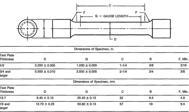
All-Weld-Metal Tension Test Specimen Dimensions
...
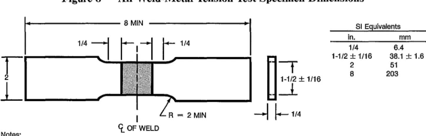
Transverse Tension Test Specimen (E6022)
...
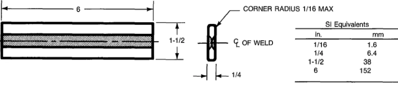
Longitudinal Guided-Bend Test Specimen (E6022)
...
BendTestJigs
...
Charpy V-Notch Impact Test Specimen
...
Dimensions of Fillet Welds
...
Alternative Methods of Facilitating Fracture of the Fillet Weld
...
Schematic of Train for Moisture Determinations
...
Order of Electrode Mandatory and Optional Supplemental Designators
...
Radiographic Acceptance Standards for Rounded Indications (Grades 1 and 2)
. . .
8 9 10
11 12 17 18 21 21 22 22 24 25 26 26 31
ix
I. Scope
This specification prescribes requirements for the classification of carbon steel electrodes for shielded metal arc welding.
Part A
General Requirements
2. Classification
2.1 The welding electrodes covered by this specifi- cation are classified according to the following:
(1) Type of current (Table 1) (2) Type of covering (Table I) (3) Welding position (Table 1)
(4) Mechanical properties of the weld metal in the as-welded or aged condition (Tables 2 and 3) 2.2 Material classified under one classification shall not be classified under any other classification in this specification, except that E701 8M may also be classified as E701 8 provided the electrode meets all of the requirements of both classifications.
3. Acceptance
Acceptance’ of the welding electrodes shall be in accordance with the provisions of the ANSIIAWS A5.01, Filler Metal Procurement Guidelines.2
1. See A3 (in the Appendix) for further information con- cerning acceptance, testing of the material shipped, and ANSIIAWS A5.01 Filler Metal Procurement Guidelines.
2. AWS standards can be obtained from the American
4. Certification
By affixing the AWS specification and cIassification designations to the packaging, or the classification to the product, the manufacturer certifies that the prod- uct meets the requirements of this spe~ifïcation.~
5. Units of Measure and Rounding- Off Procedure
5.1 U. S. Customary Units are the standard units of measure in this specification. The SI Units are given as equivalent values to the U.S. Customary Units.
The standard sizes and dimensions in the two systems are not identical, and for this reason, conversion from a standard size or dimension in one system will not always coincide with a standard size or dimension in the other. Suitable conversions, encompassing stan- dard sizes of both, can be made, however, if appropri- ate tolerances are applied in each case.
5.2 For the purpose of determining conformance with this specification, an observed or calculated value shall be rounded to the “nearest unit” of the last right-hand place of figures used in expressing the lim- iting value in accordance with the round-off method of ASTM Practice E29 for Using SigniJicant Digits in Test Data to Determine Conformance with Specijìca- ti on^.^
Welding Society, 550 N.W. LeJeune Road, P. O. Box 351040, Miami, Florida 33135.
3. See A4 (in the Appendix) for further information con- cerning certification and the testing called for to meet this requirement.
4. ASTM standards can be obtained from the American So- ciety for Testing and Materials, 19 16 Race Street, Philadel- phia, Pennsylvania 19103.
AWS A 5 . 1
71
0784265 0011772 72
~~ ~~~~
Table 1
Electrode Classification
~~ ~ ~
AWS Welding Type of
Classification Type of Covering Positiona Currentb
E6010 E601 1 E60 12 E6013 E60 19
High cellulose sodium F,V,OH,H dcep
High cellulose potassium F,V,OH,H ac or dcep
High titania sodium F,V,OH,H ac or dcen
High titania potassium F,V,OH,H ac, dcep or dcen
Iron oxide titania potassium F,V,OH,H, ac, dcep or dcen
E6020 High iron oxide ac or dcen
ac, dcep or dcen
E6022C High iron oxide ac or dcen
E6027 High iron oxide, iron
powder
{ F-fi11ets
ac or dcenac, dcep or dcen
E70 14 Iron powder, titania
E70 1 5d Low hydrogen sodium
E70 1 6d Low hydrogen potassium
E70 1 8d Low hydrogen potassium,
E7018M E7024d
iron powder
Low hydrogen iron powder Iron powder, titania
E7027 High iron oxide, iron
Low hydrogen potassium, Low hydrogen potassium,
powder iron powder iron powder
F,V,OH,H F,V,OH,H F,V,OH,H F,V,OH,H F,V,OH,H H-fillets,F
{
P l e t sac, dcep or dcen dcep
ac or dcep ac or dcep dcep
ac, dcep or dcen ac or dcen ac, dcep or dcen
H-fillets,F ac or dcep
F,OH,H,V-down ac or dcep
Notes:
a. The abbreviations indicate the welding positions as follows:
F = Flat H = Horizontal
H-fillets = Horizontal fillets
V-down = Vertical with downward progression
V = Vertical
]
[For electrodes 3/16 in. (4.8mm) and under, except 5/32 in. (4.0mm) OH = Overhead and under for classifications E7014, E701 5 , E7016, E701 8, and E701 8M.b. The term “dcep” refers to direct current electrode positive (dc, reverse polarity). The term “dcen” refers to direct current electrode negative (dc, straight polarity).
c. Electrodes of the E6022 classification are intended for single-pass welds only.
d. Electrodes with supplemental elongation, notch toughness, absorbed moisture, and diffusible hydrogen requirements may be further identified as shown in Tables 2, 3, 10, and 11.
Part B
Tests, Procedures, and Requirements
6. Summary of Tests
The tests required for each classification are spec- ified in Table 4. The purpose of these tests is to de- termine the chemical composition, mechanical
properties, and soundness of the weld metal; mois- ture content of the low hydrogen electrode cover- ing; and the usability of the electrode. The base metal for the weld test assemblies, the welding and testing procedures to be employed, and the results required are given in Sections 8 through 17.
The supplemental tests for absorbed moisture, in Section 16, Absorbed Moisture Test, and diffusible hydrogen, in Section 17, Diffusible Hydrogen Test, are not required for classification of the low hydro- gen electrodes except for E701 8M, where these are required. See Notes j a n d n of Table 4.
AWS
Classification
Tensile Strength at 0.2% Offset
ksi MPa ksi MPa in. (50.8 mm)
Percent E6010
E601 1 E60 12 E6013 E60 19 E6020 E6022d E6027 E7014 E70 1 5 E701 6 E701 8 E7024 E7027 E7028 E7048 E70 1 SM
60 60 60 60 60 60 60 60 70 70 70 70 70 70 70 70 note g
414 414 414 414 414 414 414 414 482 482 482 482 482 482 482 482 482
48 33 1
48 33 1
48 33 1
48 331
48 33 1
48 33 1
48 33 1
58 399
58 399 58 399 58 399 58 399 58 399
58 399
58 399
53-72f 365-496f
not specified
22 22 17 17 22 22 not specified
22 17 22 22 22 1 7e 22 22 22 24 Notes:
a. See Table 4 for sizes to be tested.
b. Requirements are in the as-welded condition with aging as specified in 11.3.
c. Single values are minimum.
d. A transverse tension test, as specified in 11.2 and Figure 9 and a longitudinal guided bend test, as specified in Sec- tion 12, Bend Test, and Figure 10, are required.
e. Weld metal from electrodes identified as E7024-1 shall have elongation of 22 % minimum.
f. For 3/32 in. (2.4mm) electrodes, the maximum for the yield strength shall be 77 ksi (531 MPa).
g. Tensile strength of this weld metal is a nominal 70 ksi (482 MPa).
7. Retest
If the results of any test fail to meet the require- ment, that test shall be repeated twice. The results of both retests shall meet the requirement. Speci- mens for retest may be taken from the original test assembly or from a new test assembly. For chemical analysis, retest need be only for those specific ele- ments that failed to meet the test requirement.
8. Weld Test Assemblies
8.1 One or more of the following five weld test as- semblies are required.
(1) The weld pad in Figure 1 for chemical analysis of the undiluted weld metal
(2) The groove weld in Figure 2 for mechanical properties and soundness of the weld metal
(3) The fillet weld in Figure 3 for the usability of the electrode
(4) The groove weld in Figure 4 for transverse tensile and longitudinal bend tests for welds made with the E6022 single pass electrode
(5) The groove weld in Figure 5 for mechanical properties and soundness of weld metal made with the E701 8M electrode
The sample for chemical analysis may be taken from a low dilution area either in the groove weld in Figure 2 or 5 or in the fractured all-weld-metal ten- sion test specimen, thereby avoiding the need to make a weld pad. In case of dispute, the weld pad shall be the referee method.
8.2 Preparation of each weld test assembly shall be as prescribed in 8.3 through 8.5. The base metal for each assembly shall be as required in Table 5 and shall meet the requirements of the ASTM specifica- tion shown there or an equivalent specification.
Testing of the assemblies shall be as prescribed in Sections 9 through 14.
AWS A 5 - 1 91 W 0 7 8 4 2 b 5 0011774 2 W
4
Table 3
Charpy V-Notch Impact Requirements
Limits for 3 out of 5 Specimensa AWS
Classification Average, Min. Single Value, Min.
E6010, E601 1, E6027, E701 5, E70 1 6b, E70 1 Sb, E7027, E7048 E60 19
E7028
1
E60 12, E60 1 3, E6020, E6022, E70 14, E7024b
E70 1 SM
20 ft-lb at -20°F (27 J at -29°C)
15 ft-lb at -20°F (20 J at -29°C) 20 ft-lb at 0°F
(27 J at -1 8 “C)
15 ft-lb at 0°F (20 J at -18°C)
Not Specified Not Specified
Limits for 5 out of 5 SpecimensC
Average, Min. Single Value, Min.
50 ft-lb at -20°F 40 ft-lb at -20°F
(67 J at -29°C) (54 J at -29°C)
~
Notes:
a. Both the highest and lowest test values obtained shall be disregarded in computing the av- erage. Two of these remaining three values shall equal or exceed 20 ft-lb (27 J).
b. Electrodes with the following optional supplemental designations shall meet the lower tem- perature impact requirements specified below:
Charpy V-Notch Impact Requirements,
AWS Electrode Limits for 3 out of 5 specimens (Refer to
Classification Designation Note a above)
Average, Min. Single Value, Min.
20 ft-lb at -50°F 15 ft-lb at -50°F E70 16
E701 8 E7018-1 (27 J at -46°C) (20 J at -46°C)
E7024 E7024-1 20 ft-lb at 0 ° F 15 ft-lb at 0°F
(27 J at -18°C) (20 J at -18°C) E7016-1
I
~~
c. All five values obtained shall be used in computing the average. Four of the five values shall equal, or exceed, 50 ft-lb (67 J).
Electrodes other than low hydrogen electrodes shall be tested without “conditioning”. Low hydro- gen electrodes, if they have not been adequately protected against moisture pickup in storage, shall be held at a temperature of 500 to 800°F (260 to 427 “ C ) for a minimum of one hour prior to testing.
8.3 Weld Pad. A weld pad, when required, shall be prepared as specified in Figure 1. Base metal of any convenient size of the type specified in Table 5 shall be used as the base for the weld pad. The surface of
the base metal on which the filler metal is deposited shall be clean. The pad shall be welded in the flat position with multiple layers to obtain undiluted weld metal. The preheat temperature shall not be less than 60°F (16°C) and the interpass tempera- ture shall not exceed 300°F (1 50°C). The slag shall be removed after each pass. The pad may be
quenched in water between passes. The dimensions of the completed pad shall be as shown in Figure 1.
Testing of this assembly shall be as specified in Sec- tion 9, Chemical Analysis.
m m m m m
P d d d 2
2
x z z z z z z
Pl
s 2
i - 2 o ; ?
a
2
oFI W
a o a
2
o cd
T-
E:
2
O2
W
m o\
O
4 4
W O
2
WO O m
3
W C
ü
-0 cd C o cd
m m
O W W
b O Pl W
W
a o
4
2 Lì
O
W
E E
.,-I
d4 4
o a o
cd
03
e
N Co dO784265 0033778 T W
8
L, LENGTH (SEE NOTE 9)
WELD METAL W, WIDTH
(SEE NOTE 9)
H, HEIGHT
(SEE
‘
NOTE 9) BASE METAL4
Notes:
1. Base metal of any convenient size, of any type specified in Table 5, shall be used as the base for the weld pad.
2. The surface of the base metal on which the filler metal is to be deposited shall be clean.
3. The pad shall be welded in the flat position with successive layers to obtain undiluted weld metal.
4. One pad shall be welded for each type of current shown in Table 4 except for those classifications identified by note L in Table 4.
5. The number and size of the beads will vary according to the size of the electrode and the width of the weave, as well as the amperage employed.
6. The preheat temperature shall not be less than 60°F (16°C) and the interpass temperature shall not exceed 300°F (150°C).
7. The slag shall be removed after each pass.
8. The test assembly may be quenched in water between passes to control lnterpass temperature.
9. The minimum completed pad size shall be at least four layers in height (H) with length (L) and width (W) sufficient to perform analysis. The sample for analysis shall be taken at least 114 in. (6.4 mm) above the original base metal surface.
Figure 1 - Pad for Chemical Analysis of Undiluted Weld Metal
8.4 Groove Weld
8.4.1 Mechanical Properties and Soundness. A test assembly shall be prepared and welded as speci- fied in Figures 2 or 5 using base metal of the appro- priate type specified in Table 5. Testing of this assembly shall be as specified in Section 1 1, Tension Test, and Section 13, Impact Test. The assembly shall be tested in the as-welded or aged condition.
8.4.2 Transverse Tension and Bend Tests. A test assembly shall be prepared and welded as specified in Figure 4 using base metal of the appropriate type specified in Table 5. Testing of this assembly shall be as specified in 1 1.2 through 1 1.4 and Section 12,
Bend Test. The assembly shall be tested in the aged condition.
8.5 Fillet Weld. A test assembly shall be prepared and welded as specified in Table 4 and Figure 3 using base metal of the appropriate type specified in Table
5 . The welding positions shall be as specified in Table
6 and Figures 3 and 6 according to the size and classi- fication of electrode. Testing of the assembly shall be as specified in Section 14, Fillet Weld Test.
9. Chemical Analysis
9.1 The sample for analysis shall be taken from weld metal obtained with the electrode. The sample shall come from a weld pad or from a low dilution area in the fractured all-weld-metal tension speci- men or the groove weld in Figures 2 or 5. Areas where arc starts or craters exist shall be avoided.
The top surface of the pad described in 8.3 and shown in Figure 1 shall be removed and discarded, and a sample for analysis shall be obtained from the underlying metal by any appropriate mechanical means. The sample shall be free of slag and shall be taken at least 1/4 in. (6.4 mm) from the nearest sur- face of the base metal.
The low dilution area in the fractured tension test specimen or in the groove weld in Figures 2 or 5 shall be prepared for analysis by any suitable me- chanical means.
9.2 The sample shall be analyzed by accepted ana- lytical methods. The referee method shall be ASTM Standard Method E350, Chemical Analysis of Car- bon Steel, Low Alloy Steel, Silicon Electrical Steel, Ingot Iron and Wrought Iron.
9.3 The results of the analysis shall meet the re- quirements of Table 7 for the classification of the electrode under test.
IO. Radiographic Test
10.1 When required in Table 4, the groove weld de- scribed in 8.4. l and shown in Figure 2 or 5 shall be radiographed to evaluate the soundness of the weld metal. In preparation for radiography, the backing shall be removed, and both surfaces of the weld shall be machined or ground smooth. The finished surface of the weld may be flush with the plate or
-
1 MIN(A) TEST ASSEMBLY SHOWING LOCATION OF TEST SPECIMEN
WELD SECTION AA WELD
$
SECTION BB(B) ORIENTATION AND LOCATION OF (C) LOCATION OF ALL-WELD-METAL
IMPACT TEST SPECIMEN TENSION TEST SPECIMEN
SI Equivalents in. mm
1 14 6.4
1 25
5 127
10 254
- -
D
Electrode Sizein. mm
(T) Plate Thickness
in. mm
Root Opening (R) in. mm
Passes Per Laver
Total Lavers 3132 2.4
118 3.2 5/32 4.0 3/16 4.8 7/32 5.6 114 6.4 5/16 8.0
112 13 112 13 314 20 314 20 314 20
1 25
1-114 32
318 10 2
112 13 2
518 16 2
314 20 2 718 23 2
1 25 2
1-118 28 2
I not specified 5 to 7 7 to 9 6 to 8 6 to 8 9 to 1 1 10 to 12 Notes:
1. All dimensions except angles are in inches.
2. For electrodes longer than 18 in. (450 mm), a 20 in. (500 mm) minimum length test assembly shall be welded.
3. Base metal shall be as specified in Table 5.
4. The surfaces to be welded shall be clean.
5. Prior to welding, the assembly may be preset to yield a welded joint sufficiently flat to facilitate removal of the test specimens.
As an alternative, restraint or a combination of restraint and presetting may be used to keep the welded joint within 5 deg of plane. A welded test assembly that is more than 5 deg out of plane shall be discarded. Straightening of the test assembly is prohibited.
6. Welding shall be in the flat position, using each type of current specified in Table 4 except for classifications identified by Note L in Table 4.
7. The preheat temperature shall be 225°F (105°C) minimum. The interpass temperature shall not be less than 225°F (105°C) nor more than 350°F (175°C).
8. The joint root may be seal welded with 3/32 or 118 in. (2.4 or 3.2 mm) electrodes using stringer beads.
9. In addition to the stops and starts at the ends, each pass shall contain a stop and start in between the ends.
IO. The completed weld shall be at least flush with the surface of the test plate.
Figure
2- Groove Weld Test Assembly for Mechanical Properties and
Soundness Except for E6022 and E7018M Electrodes
c
APPROX 1 IN.,
CUT HERE FOR
MACRO EXAMINATION SECTION END OF WELD MADE
WITH FIRST ELECTRODE.
SEE NOTE B IN TABLE 6.
SI Equivalents
-
in. mm
1
-
253 76
'
FLANGE TO BE STRAIGHT AND IN INTIMATE CONTACT WITH SQUARE MACHINED EDGE OF WEB MEMBER ALONG ENTIRE LENGTH TO ENSURE MAXIMUM RESTRAINT 10Notes:
1. See Table 6 for values of T and L.
2. Base metal shall be as specified in Table 5.
3. The surfaces to be welded shall be clean.
4. An assembly shall be welded in each position specified in Table 6 and shown in Figure 6 using each type of current specified in 5 . The preheat shall be 60°F (16°C) minimum.
6. A single pass fillet weld shall be made on one side of the joint. The first electrode shall be consumed to a stub length no greater 7. Welding in the vertical position shall be with upward progression, except for the E7048 classification where progression shall be 8. Weld cleaning shall be limited to slag chipping, brushing, and needle scaling. Grinding or filing of the weld face in prohibited.
Table 4.
than 2 in. (50 mm).
downward.
Figure 3 - Fillet Weld Test Assembly
10 MIN
7 1
1
1 I4
f
I
6
c I
1/16 MAX ROOT OPENING
LONGITUDINAL BEND TEST SPECIMEN (SEE FIGURE IO)
SI Equivalents
102 153
Notes:
1. All dimensions are in inches.
2. Base metal shall be as specified in Table 5.
3. The surfaces to be welded shall be clean.
4. Prior to welding, the assembly may be preset to yield a welded joint sufficiently flat to facilitate removal of the test specimens. As an alternative, restraint or a combination of restraint and presetting may be used to keep the welded joint within 5 deg of pfane. A welded test assembly that is more than 5 deg out of plane shall be discarded. Straightening of the test assembly is prohibited.
5. The assembly shall be welded in the flat position, uslng the type of current specified in Table 4.
6. The preheat temperature shall be 60°F (16°C) min. The interpass temperature shall not exceed 350°F (180°C).
7. In addition to the stops and starts at the ends, each pass shall contain a stop and start in between the ends.
8. Back gouging may be done to ensure sound weld metal through the entire thickness of test assembly.
9. The completed weld shall be at least flush with the surface of the test plate.
Figure 4 - Test Assembly for Transverse Tension and Longitudinal Guided Bend Tests
for Welds Made With E6022 Electrodes
AWS A 5 - L 91 M 0784265 OOLZ782 Z
t
P- '
MIN lot" -li
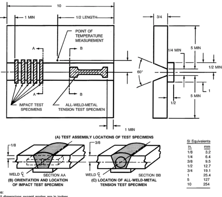
Il2 LENGTTEMPERATURE MEASUREMENT POINT OF TEMPERATURE MEASUREMENT
A
Bl
!
__c
I
SPECIMENS TENSION TEST SPECIMEN
I I
i -
314-¡
1 MIN(A) TEST ASSEMBLY LOCATIONS OF TEST SPECIMENS
(B) ORIENTATION AND LOCATION (C) LOCATION OF ALL-WELD-METAL OF IMPACT TEST SPECIMEN TENSION TEST SPECIMEN
Notes:
1. All dimensions except angles are in inches.
2. Base metal shall be as specified in Table 5.
3. The surfaces to be welded shall be clean.
t
114 MIN 5 MIN
I
I-1
SI Equivalents
in. mm
118 3.2
1 I4 6.4
318 9.5
112 12.7
314 19.1
1 25.4
5 127
10 254
- -
4. Prior to welding, the assembly may be preset to yield a welded joint sufficiently flat to facilitate removal of the test specimens. As an alternative, restraint or a comblnation of restraint and presetting may be used to keep the welded joint within 5 deg of plane. A welded test assembly that is more than 5 deg out of plane shall be discarded. Straightening of the test assembly is prohibited.
5. The assembly shall be welded in the vertical position with progression upward for electrodes 5/32 in. (4.0 mm) and less in size, and in the flat position for electrodes 3116 in. (4.8 mm) and greater in size, using the type of current specified in Table 4 for the electrode and welding technique recommended by the electrode manufacturer.
6. The preheat temperature and the interpass temperature shall be 200-250°F (93-121 "C).
7. The welding heat input shall be 30 to 40 kJlin. (12 to 16 kJ/cm) for the 3/32 in. (2.4 mm) size electrodes and 50 to 60 kJ/in. (20 8. In addition to the stops and starts at the ends, each pass shall contain a stop and start in between the ends.
9. The completed weld shall be at least flush with the surface of the test plate. Maximum weld reinforcement shall be 3/16 in. (4.8 to 24 kJlcm) for the 118 in. (3.2 mm) slze and larger electrodes.
mm). Peening of weld beads is not permitted.
Figure 5 - Groove Weld Test Assembly for Mechanical Properties and Soundness of
Weld Metal Made with E7018M Electrodes
ASTM UNS
AWS Classification Type Specificationa Numberb
A131 Grade B KO2 102
All Carbon steel A285 Grade A KO 1700
A285 Grade B KO2200
A285 Grade C KO2801
{
A36 A283 Grade DAll except E7018M Carbon steeI KO2600
A29 Grade 1015 G10150 A29 Grade 1020 G10200
-
Notes:
a. Equivalent steel may be used.
b. SAE/ASTM Unified Numbering System for Metals and Alloys.
have a reasonably uniform reinforcement not ex- ceeding 3/32 in. (2.4 mm). Both surfaces of the test assembly in the area of the weld shall be smooth enough to avoid difficulty in interpreting the radio- graph.
10.2 The weld shall be radiographed in accordance with ASTM Method E142, Controlling Quality of Radiographic Testing. The quality level of inspec- tion shall be 2-2T.
10.3 The soundness of the weld metal meets the re- quirements of this specification if the radiograph shows the following:
(1) No cracks, no incomplete fusion or incom- plete joint penetration
(2) No slag inclusions longer than 1/4 in. (6.4 mm) or 1/3 of the thickness of the weld, whichever is greater, or no groups of slag inclusions in line that have an aggregate length greater than the thickness of the weld in a length 12 times the thickness of the weld, except when the distance between the succes- sive inclusions exceeds 6 times the length of the longest inclusions in the group
(3) No rounded indications in excess of those per- mitted by the radiographic standards in Figure 7 ac- cording to the grade specified in Table 8.
One in. (25 mm) of the weld measured from each end of the assembly shall be excluded from radio- graphic evaluation.
10.4 A rounded indication is an indication (on the radiograph) whose length is no more than three times its width. Rounded indications may be circu- lar, elliptical, conical, or irregular in shape, and they may have “tails”. The size of a rounded indication is the largest dimension of the indication, including any tail that may be present.
The indication may be porosity or slag. Indica- tions whose largest dimension does not exceed 1/64 in. (0.4 mm) shall be disregarded. Test assemblies with porosity indications larger than the largest rounded indications permitted in the radiographic standards do not meet the requirements of this specification.
11. Tension Test
11.1 One all-weld-metal tension test specimen shall be machined from the groove weld described in 8.4.1 as shown in Figure 2 or 5. The dimensions of the specimen shall be as shown in Figure 8.
11.2 For E6022 electrodes, one transverse tension test specimen shall be machined from the groove weld described in 8.4.2 and Figure 4. The dimen- sions of the specimen shall be as shown in Figure 9.
11.3 The tension specimens for all electrodes ex- cept the low hydrogen classifications shall be aged at 200 to 220°F (95 to 105’C) for 48 f 2 hours, and cooled in air to room temperature. All specimens
O 0 0 0
z z z z z z z z z
0 0 0 0 0
z z z
O 0 0
z z z
O 0 0
ö O d
ö O d
ö O d
ö O d
o" ö o" o"
0 0 0 0 0 0 0 0 0 0 0 0 0 0 0 0 0 0 0 0 0 0 0 0 0 0 0 0 0 1 0 0 0 0 0 0 0 m m 0 0 0 0 0 0 0 0 0 0 0 0 0 1 0 0 0 0 0 0 0
N m m m m d - d - N m m m m d d m m m m m T t * c . 1 m m m m d d
% ö
m
9
O g
O d
ö%%a
öo m m m
d W W \ O O
s s s
OW 0h 0k 0k do"
0 0 0 0 0 0 0 0 0 0 0 0 0 0 0 0 0 0 0 0 O 0 0
m o o o o o o 0 0 0 0 0 0 m o o o o o o O 0 0
m m m m m d d m m m d d d m m m m d - d d m m m
""
Co O
O m
%
AWS A 5 . 1 91 0 7 8 4 2 6 5 0 0 1 1 7 8 b 9
16
v,
v
4
W
8
O O c?
O
2
o o o o o ö ö ö o o ö o o ö ö ö r D \ D w \ D w \ D w \ o r - F r - r - P r - P r - 3 0 0 0 0 0 0 0 O 0 0 O 0 0 O 0
3 3 3 3 3 3 3 3 3 3 3 3 3 3 3 3
Z 4 4 4 A f i ~ r q z - l m 24cq t-.l*
3 0 0 0 0 0 0 0 O 0 0 O 0 0 O 0 Q W W W W W W W r - r - r - r - r - r - r - r -
r l w w w C r l C r l w w w w w w w w w w
O 0
o - 7
oz
2 ò
4
O r-
z
s
W O
4
/-
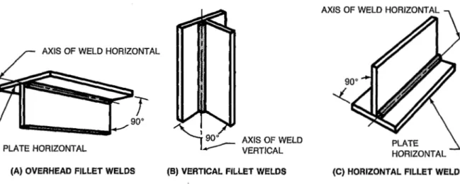
AXIS OF WELD HORIZONTALL
PLATE HORIZONTAL PLATE-1
HORIZONTAL (A) OVERHEAD FILLET WELDS (B) VERTICAL FILLET WELDS (C) HORIZONTAL FILLET WELDS
Figure 6 - Welding Positions for Fillet Weld Test Assemblies
shall be tested in the manner described in the ten- sion testing section ofAWS B4.0, StandardMethods fos Mechanical Testing of Welds.
11.4 The results of the tension test shall meet the requirements specified in Table 2.
B 12. Bend Test (For E6022 Electrodes Only)
12.1 One longitudinal face bend specimen, as re- quired in Table 4, shall be machined from the groove weld test assembly described in 8.4.2 and shown in Figure 4. Dimensions of the specimen shall be as shown in Figure 10.
12.2 The bend specimen shall be aged at 200 to 220°F (95 to 105 "C) for 48 +2 hours then air cooled to room temperature and tested as required in 12.3.
12.3 The specimen shall be tested in the manner described in the bend testing section of AWS B4.0, Standard Methods for Mechanical Testing of Welds.
The specimen shall be bent uniformly through 180 degrees over a 3/4 in. (1 9 mm) radius in any suitable jig. Three standard jigs are shown in Figure 1 1. Po- sitioning of the face bend specimen shall be such that the weld face of the last side welded is in ten-
O
sion.12.4 Each specimen, after bending, shall conform to the 3/4 in. (19 mm) radius, with an appropriate allowance for springback and the weld metal shall
Table 8
Radiographic Soundness Requirements AWS
Classification Radiographic StandardaJb
Grade 2
-~
EGO 19 E6020
E70 1 5 Grade 1
E70 16 E70 18 E7018M E7048 E6010 E60 1 1 E60 13 E70 14 E7024 E6027 E7027
E7028 EGO 12
1
Not specifiedE6022
}
Notes:
a. See Figure 7.
b. The radiographic soundness obtainable under actual industrial conditions employed for the various elec- trode classifications is discussed in A6.10.1 in the Ap- pendix.
~~~~~~~~
18
a O
a
o O
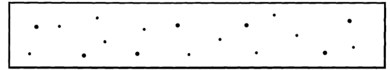
(A) ASSORTED ROUNDED INDICATIONS
SIZE 1/64 in. (0.4 mm) TO 1/16 in. (1.6 mm) IN DIAMETER OR IN LENGTH. MAXIMUM NUMBER OF INDICATIONS IN ANY 6 in.
(150 mm) OF WELD = 18, WITH THE FOLLOWING RESTRICTIONS:
MAXIMUM NUMBER OF LARGE 3/64 in. (1.2 mm) TO 1/16 in. (1.6 mm) IN DIAMETER OR IN LENGTH INDICATIONS = 3.
MAXIMUM NUMBER OF MEDIUM 1/32 in. (0.8 mm) TO 3/64 in. (1.2 mm) IN DIAMETER OR IN LENGTH INDICATIONS = 5.
MAXIMUM NUMBER OF SMALL 1/64 in. (0.4 mm) TO 1/32 in. (0.8 mm) IN DIAMETER OR IN LENGTH INDICATIONS = 10.
(B) LARGE ROUNDED INDICATIONS SIZE 3/64 in. (1.2 mm) TO 1/16 in. (1.6 mm) IN DIAMETER OR IN LENGTH.
MAXIMUM NUMBER OF INDICATIONS IN ANY 6 in. (150 mm) OF WELD = 8.
c
(C) MEDIUM ROUNDED INDICATIONS SIZE 1/32 in. (0.8 mm) TO 3/64 in. (1.2 mm) IN DIAMETER OR IN LENGTH.
MAXIMUM NUMBER OF INDICATIONS IN ANY 6 in. (150 mm) OF WELD = 15.
(D) SMALL ROUNDED INDICATIONS SIZE 1/64 in. (0.4 mm) TO 1/32 in. (0.8 mm) IN DIAMETER OR IN LENGTH.
MAXIMUM NUMBER OF INDICATIONS IN ANY 6 in. (150 mm) OF WELD = 30.
Notes:
1. In using these standards, the chart which is most representative of the size of the rounded indications present in the test 2. Since these are test welds specifically made in the laboratory for classification purposes, the radiographic requirements for these 3. Indications whose largest dimension does not exceed 1/64 in. (0.4 mm) shall be disregarded.
specimen radiograph shall be used for determining conformance to these radiographic standards.
test welds are more rigid than those which may be required for general fabrication.
Figure 7 - Radiographic Acceptance Standards for Rounded Indications
(Grade 1)
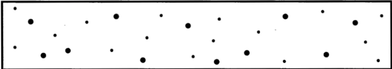
(E) ASSORTED ROUNDED INDICATIONS SIZE 1/64 ln. (0.4 mm) TO 5/64 in. (2.0 mm) IN DIAMETER OR IN LENGTH.
MAXIMUM NUMBER OF INDICATIONS IN ANY 6 in. (150 mm) OF WELD = 27, WITH THE FOLLOWING RESTRICTIONS:
MAXIMUM NUMBER OF LARGE 1/16 in. (1.6 mm) TO 5/64 in. (2.0 mm) IN DIAMETER OR IN LENGTH INDICATIONS = 3.
MAXIMUM NUMBER OF MEDIUM 3/64 in. (1.2 mm) TO 1/16 in. (1.6 mm) IN DIAMETER OR IN LENGTH INDICATIONS = 8.
MAXIMUM NUMBER OF SMALL 1/64 in. (0.4 mm) TO 3/64 in. (1.2 mm) IN DIAMETER OR IN LENGTH INDICATIONS = 16.
O
O O O O
O O
O O
O O O O O
(F) LARGE ROUNDED INDICATIONS SIZE 1/16 in. (1.6 mm) TO 5/64 in. (2.0 mm) IN DIAMETER OR IN LENGTH.
MAXIMUM NUMBER OF INDICATIONS IN ANY 6 in. (150 mm) OF WELD = 14.
O O
O O O
O
O O O O
O O
O O O O
O O O
O O
(G) MEDIUM ROUNDED INDICATIONS SIZE 3/64 in. (1.2 mm) TO 1/16 in. (1.6 mm) IN DIAMETER OR IN LENGTH.
MA XI MUM NUMBER OF INDICATIONS IN ANY 6 in. (150 mm) OF WELD = 22.
(H) SMALL ROUNDED INDICATIONS SIZE 1/64 in. (0.4 mm) TO 3/64 in. (1.2 mm) IN DIAMETER OR IN LENGTH.
MAXIMUM NUMBER OF INDICATIONS IN ANY 6 in. (150 mm) OF WELD = 44.
Notes:
1. In using these standards, the chart which is most representative of the size of the rounded indications present in the test 2. Since these are test welds specifically made in the laboratory for classification purposes, the radiographic requirements for these 3. Indications whose largest dimension does not exceed 1/64 in. (0.4 mm) shall be disregarded.
specimen radiograph shall be used for determining conformance to these radiographic standards, test welds are more rigid than those which may be required for general fabrication.
Figure 7 (Continued) - Radiographic Acceptances Standards for Rounded Indications
(Grade 2)
AWS A 5 . L 91 W 0 7 8 4 2 b 5 OOLL790
O
20
not contain openings in excess of 1/8 in. (3.2 mm) on the convex surface.
13. Impact Test
13.1 Five.Charpy V-notch impact test specimens, Figure 12, shall be machined from the test assembly shown in Figure 2 or 5, for those classifications for which impact testing is required in Table 4.
13.2 The five specimens shall be tested in accord- ance with the fracture toughness testing section of AWS B4.0, Standard Methods for Mechanical Test- ing of Welds. The test temperature shall be that specified in Table 3 for the classification under test.
13.3 In evaluating the test results for all the classi- fications that require impact testing, except E70 18M, the lowest and the highest values obtained shall be disregarded. Two of the three remaining values shall equal, or exceed, the specified 20 ft-lb (275) energy level. One of the three may be lower, but not lower than 15 ft-lb (205). The average of the three shall not be less than the required 20 ft-lb (275) energy level.
13.4 In evaluating the results for E701 8M, all five values shall be used. Four of the five values shall equal, or exceed, the specified 50 ft-lb (675) energy level. One of the five may be lower, but not lower than 40 ft-lb (545). The average of the five shall not be less than the required 50 fi-lb (675) energy level.
14. Fillet Weld Test
14.1 The fillet weld test, when required in Table 4, shall be made in accordance with 8.5 and Figure 3.
The entire face of the completed fillet weld shall be examined visually. It shall be free of cracks, overlap, slag, and porosity, and shall be substantially free of undercut. An infrequent short undercut up to 1/32 in. (0.8 mm) depth shall be allowed. After the visual examination, a specimen, approximately
1 in. (25 mm) in length, shall be removed as shown in Figure 3. One cross-sectional surface of the speci- men shall be polished, etched, and then examined as required in 14.2.
14.2 Scribe lines shall be placed on the prepared surface, as shown in Figure 13, and the fillet weld size, fillet weld leg, and convexity shall be deter- mined to the nearest 1/64 in. (0.4 mm) by actual measurement (see Figure 13). These measurements shall meet the requirements of Table 6 with respect to minimum or maximum fillet weld size and the requirements of Table 9 with respect to maximum convexity and maximum difference between fillet weld legs according to the fillet weld size measured.
14.3 The remaining two sections of the test as- sembly shall be broken through the fillet weld by a force exerted as shown in Figure 14. When neces- sary to facilitate fracture through the fillet, one or more of the following procedures may be used:
(1) A reinforcing bead, as shown in Figure 14, may be added to each leg of the weld.
Table 9
Dimensional Requirements for Fillet Weld Usability Test Specimens Maximum
Measured Fillet Maximum Difference Between
Weld Size Convexity Fillet Weld Legs
in. mm in. mm in. mm
118 5/32 311 6 7/32 1 /4 9/32 511 6 11/32 318
3.2 4.0 4.8 5.6 6.4 7. I 8.0 8.7 9.5
3/64 3/64 1/16 1/16 1/16 1/16 5/64 5/64 5/64
1.2 1.2 1.6 1.6 1.6 1.6 2.0 2.0 2.0
1/32 3/64
1/16 5/64 3/32 7/64 118 9/64 5/32
0.8 1.2 1.6 2.0 2.4 2.8 3.2 3.6 4.0
Dimensions of Specimen, mm Test Plate
Thickness D G C B F, Min.
12.7 6.40 +. 0.13 25.40 -t- 0.13 32 9.5 4.8
19 and 12.70 k 0.25 50.80 +- 0.13 57 19 9.5
larger Notes:
Dimensions G and C shall be as shown, but ends may be of any shape to fit the testing machine holders as long as the load is axial.
The diameter of the specimen within the gauge length shall be slightly smaller at the center than at the ends. The difference shall not exceed one percent of the diameter.
When the extensometer is required to determine yield strength, dimension C may be modified. However, the percent of the elongation shall be based on dimension G.
The surface finish within the C dimension shall be no rougher than 63 in.