While planning and process planning are essential in distributed manufacturing, their integration can provide added value in achieving global optimization. Huang Department of Industrial and Manufacturing Systems Engineering, University of Hong Kong Hong Kong.
K. Ong
Shaikh
Sundararajan
Y.M. Tsang
An Effective Approach for Distributed Process Planning Enabled by Event-driven Function Blocks
- Introduction
- Brief Literature Review
- Distributed Process Planning
- Fundamentals of DPP
- Basic Requirements
- System Architecture
- Enabling Technologies
- Decision Solutions for Supervisory Planning
- EMF for Machining Process Sequencing
- EMF Grouping
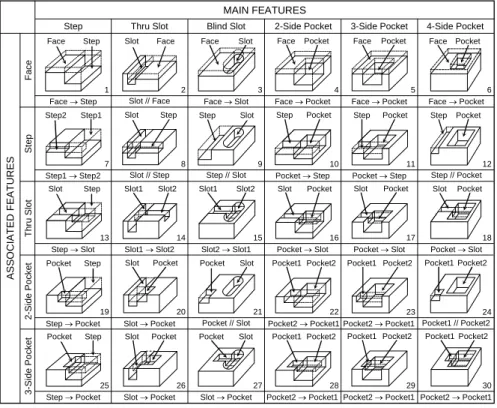
IS the kth imaginary surface of the part described by a function of a set of parameters;. The first item in the sorted results of datum dependency is the primary datum reference.
EMF T V `
- EMF Sequencing
- Function Block Design
- Setup Merging and Monitoring
- Setup Merging
- Detailed Operation Planning
- Function Block Execution Control and Monitoring
- Conclusions
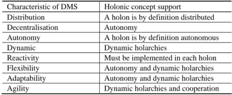
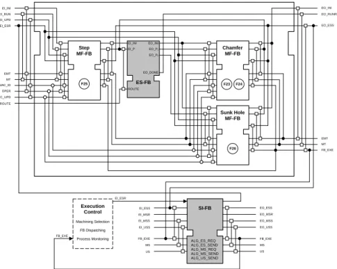
To monitor the machining process during execution, an SI-FB can be connected to a composite function block as shown in Figure 1.14. Once a combined combined function block (eg Setup-2 in Figure 1.17) has been sent to its dedicated machine, detailed operation planning is performed.
Acknowledgments
However, the detailed instructions on "how to do" a job are up to the embedded algorithms to determine at runtime. It is expected that the DPP approach will greatly increase the flexibility and adaptability of process plans, especially in fluctuating job-shop environments.
1.28] Kimura, F., 1989, "High Quality Product Realization Through the Tight Integration of Product Design and Process Planning," In Proceedings of CIRP International Workshop on CAPP, p.
Web-based Polishing Process Planning Using Data-mining Techniques
Introduction
Furthermore, another importance of process planning is to support the sharing of polishing operation knowledge and experience. The system is supported by the development of a knowledge base for optimizing polishing process parameters.
Literature Review
- Research Works in Polishing
- Web Application for Knowledge-based Planning
- Case-based Reasoning
- Fuzzy Modelling
- Genetic Algorithms
- GA-Fuzzy Systems
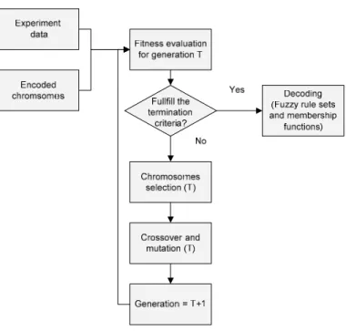
The definition of fuzzy rules and the membership functions is one of the most important questions. Genetic algorithms have been used by many researchers to generate fuzzy rules and membership functions [2.32].
Polishing Process Planning
- Purpose of Polishing Process Planning
- Design of Polishing Process Planning
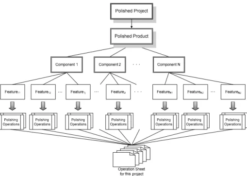
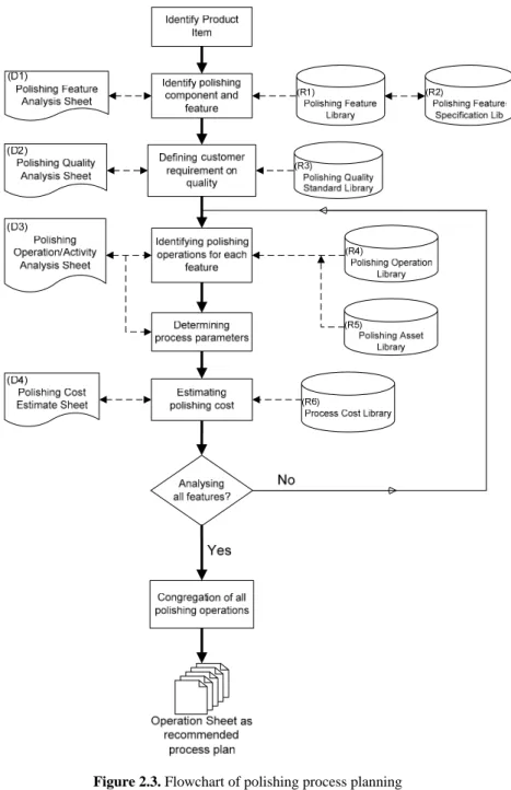
Within the flowchart, the identification of the product item is constantly referenced during process planning. Process planning is built through the selection and sequence of polishing processes and operations to produce finished products and components from initial materials.
Web-based Portal System for Polishing
- Problem Definition
- Objectives
- Design of Web-based Portal System
- Implementation of Web-based Portal System
The definition of polishing information content can be supported by this package to store key values. Products, components, polishing features, quality levels and operating process parameters can be generated for a standard meta database.
Knowledge-base Development Methodology
- General Framework
- Case Study
A fitness value will be assigned based on the proximity of the resulting part of the chromosomes and historical data. The coded values of the genes stored in the membership function range are the values of the universe of discourse defined in Table 2.4. The output part of fuzzy rule 1 is then compared with encoded data 1, which is shown in Table 2.7.
Results and Discussions
If the actual number of generations does not exceed the termination criterion, Step 9 will be needed. There is a trade-off between the number of rules, data coverage, and computation time. The optimal number of rules is the trade-off between data coverage and computation time.
Conclusions
Since the number of variables involved in the coarse-polishing process is very large, the generalized rules will be more concise and accurate if the system can acquire more data. If the number of rules increases, the percentage of data coverage will increase, but the calculation time will be longer and vice versa. In future development, it is necessary to design a methodology to determine the optimal number of rules for an individual chromosome.
Integration of Rule-based Process Selection with Virtual Machining for Distributed Manufacturing Planning
Introduction
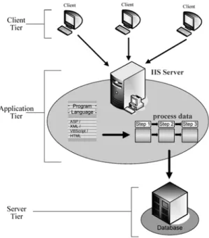
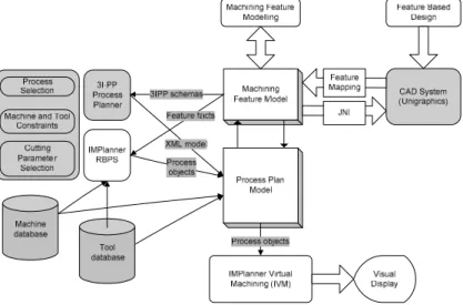
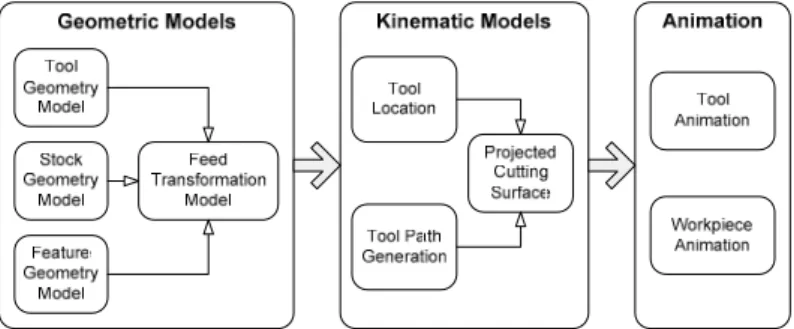
Integration of rule-based process selection with virtual machining for distributed production planning. exchange objects using CORBA), XML interface (the modules exchange tagged text streams) or communication between processes (remote method invocation, RMI). Virtual machining of selected processes is achieved by using a Java 3D tool to develop animated, hatched virtual 3D models. The virtual machining procedure, which consists of the development of geometric, kinematic and animation models, is described.
IMPlanner Architecture
A high-level scenario for the integration of process selection and virtual machining is shown by arrows in Figure 3.1. Virtual machining takes each manufacturing process object and generates the corresponding virtual world model using Java 3D. A virtual world model consists of: (a) a geometric stock, tool and feature model; (b) a kinematic synchronization model between the workpiece and the tool, and (c) an animation model that defines the behaviors and transformation of geometric models in the virtual world to perform virtual machining.
Knowledge-based Process Selection
- Knowledge Representation
- Process Selection Rules
- Integration of Rule Execution Engine into IMPlanner
The small portion of the data used in the process selection module is shown in Table 3.1 (from [3.8]). The precedent data of the process is implemented in the form of a graph, shown in figure 3.4. An example of rules developed to capture the process selection procedure is shown in Figure 3.7.
Virtual Machining of Milling Operations
- Virtual Machining Scene Graph
It captures the changing geometry of the workpiece due to the relative movement between the tool and the material. The animation of the workpiece along the tool path depends on the type of tool path movement. The fractions are "a": the time until the tool touches the workpiece; "b": the time required to create a semicircle on the upper side; "c": time until the lower cutting edge of the tool touches the entry surface; "d": the time required to create a semicircle at the bottom of the element; “i”: time after all plots are created and the tool is fully turned on; "e": time interval for opening the upper back page; “f”: time before the bottom of the function is open; “g”: time interval for opening the lower rear side; and.
Integration Approaches
- Object Visualisation Paradigm
- Distributed Approach
- Integrated Application
- XML-based Web Distributed Application
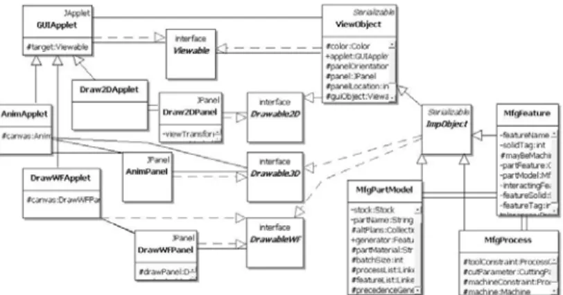
It relies on ImpObject to provide the model and data to be displayed in the scene graph form. Tree model, which provides the user with a hierarchical part model with options to select any node in the tree and review/inspect its contents. As mentioned in the previous section, IMPlanner provides an XML representation of the hierarchical process plan model that includes parts, features, and processes.
Case Study
The next step is to generate a toolpath for the process that can create the selected feature, as shown in Figure 3.31. The last step is virtual machining of the created process in the animation tab. This serves as a tool to verify the suitability of the selected process for the relevant function (see Figure 3.32).
Related Research
The major disadvantage of the system is that NC code must be generated before virtual machining, which makes it inefficient; for example, if the animation model detects problems, all the effort to generate NC code must be repeated. Several efforts have been devoted to developing a better virtual model of the physical machining process. Another drawback of these efforts is the use of VRML, a data representation language, which leaves the steps in the process planning disconnected from each other.
Conclusions
Computer numerically controlled (CNC) simulation software Vericut [3.28] has gained wide acceptance in the manufacturing industry due to its advanced, user-friendly features. Several concepts related to VM have been implemented, each built using different methodologies, modeling techniques, and representations. In contrast, our approach uses Java 3D, a procedural language that allows easier integration with other process planning and process selection tasks.
Acknowledgements
3.17] Arumugam, J., 2004, Feature Interaction Analysis and Feature Priority Network Generation for Automated Process Design, MSc Thesis, Ohio University. 3.19] Pisipati, D., 2004, Virtual pocket fabrication using multi-toolpath end milling, MSc thesis, Ohio University. 3.35] University of Michigan, 2000, Bringing the Virtual Lathe to Life, Virtual Reality Lab, http://www-vrl.umich.edu/sel_prj/lathe/index.html.
CyberCut: A Coordinated Pipeline of Design, Process Planning and Manufacture
- Introduction
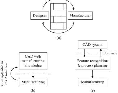
- Conventional Approach
- Manufacturing-dependent CAD Systems
- Bidirectionally Coupled CAD Systems
- The CyberCut System
- Overview of the CyberCut System
- Definition of Features
- Architecture
- WebCAD
- Feature Recogniser
- Macroplanner and Setup Planner
- Microplanner
- Tool-path Planner
- Implementation and Results
- Conclusions
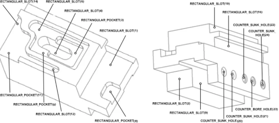
In Figure 4.3(b), the arrow from the Feature 1 shoulder to the Feature 9 hole shows the contour of the . The z-planes of the part (that is, planes with the z-axis as normal) are extracted. For example, if contour 2 is chosen, the faces of the part immediately below it (that is, the next highest z direction) are subtracted from the contour.
Process Planning, Scheduling and Control for One-of-a-Kind Production
Introduction
For example, the mobile phone can be customized in both its appearance and its functionality (eg the mobile phone plan has many options such as voicemail, call forwarding, call display and others). The design of the base product is also based on market studies that determine appearance and functional requirements. Once the base product is designed and tested, the limits of the product variations are determined and established as design constraints.
Literature Review
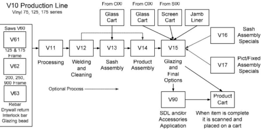
Due to the type of product mix for orders and the fact that Gienow uses an FMS, the total plant schedule must be considered. Depending on the cutting machine and the size of the material being moved, these buffers are set to 25, 50 or 100. In the case study, the production process uses fixed routes, but they do have multiple paths due to the product mix chosen by the customers through different options.
Process Planning
- Long-term Process Planning
- Short-term Process Planning
This detailed data is then stored for a period depending on the life cycle of the product or warranty terms. If so, the receiving department can deliver the lines' components at the beginning of the schedule. If closer synchronization is required, details of the main production line schedules are available.
Process Control
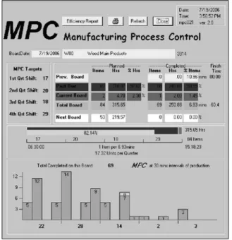
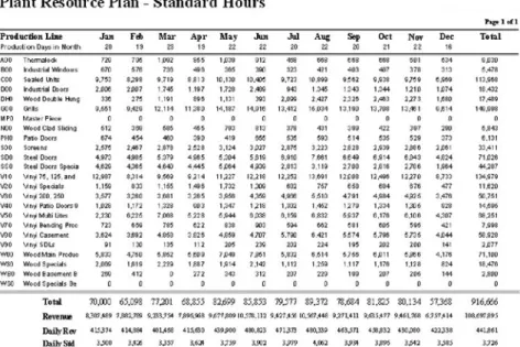
This view provides information to the supervisor to improve control over the performance of the production line. The plant totals report shown in Figure 5.8 provides daily performance information on each production line. With the information about how many staff worked on the schedule and for how long, the efficiency of each line is calculated.
Adaptive Planning and Control
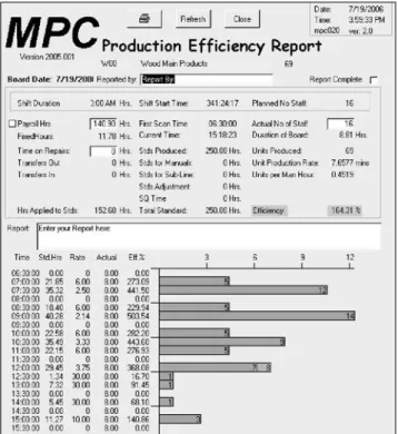
A second report as illustrated in Figure 5.10, analyzes the next four weeks of the forward charge. Constraints of the sort sequence defined in Section 5.3.2 may not produce the optimum production sequence. Therefore, using the modified colored Petri net called temporised hierarchy object-oriented colored Petri nets with variable structure.
Long-term Resource Planning
Ubmg the number of units made on a production for each branch and market over the training period;. TFUp the number of units to be produced on production line p over the forecast period. The total number of products to be made on a production line over the forecast period is determined by.
Conclusions
There is no linear relationship to overall revenue figures, as each industry and market shows some signs of different changes in its product offering. Production lines are actually showing an improvement in their efficiency, which reflects a lower need for resources.
Acknowledgment
5.21] Anderson, S., 2001, "Direct and Indirect Effects of Product Mix Characteristics on Capacity Management Decisions and Operating Performance," International Journal of Flexible Manufacturing Systems,13, pp. 5.22] Foley, W.J., 2002, "Impact of interruptions" on schedule execution in flexible manufacturing systems," International Journal of Flexible Manufacturing Systems, 14, pp. 5.28] Miltenburg, J., 2002, "Balancing and scheduling mixed-model U- shaped production lines", International Journal of Flexible Manufacturing Systems, 14, p.
Setup Planning and Tolerance Analysis
Introduction
- Current State-of-the-Art
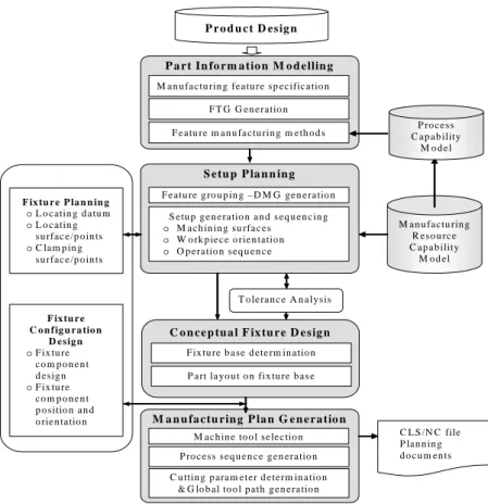
CAMP can be divided into parts information modeling, feature manufacturing strategy, manufacturing resource capability analysis, configuration planning, and equipment design. The objective of fixture design is to generate fixture configurations to hold workpieces tightly and accurately during manufacturing processes. At the machine level, no research has been conducted with the design of multi-part installations and the corresponding global toolpath generation.
Manufacturing Planning System
- Feature-based Part Information Modelling
- Feature Manufacturing Strategy
- Machine Tool Capability Modelling
- Setup Planning
- Fixture Design in Computer-aided Manufacturing Planning
- Manufacturing Plan Generation
The cutter template and tool-path template are set up based on best-practice knowledge in the industry. Then the number of setups can be significantly reduced and consequently the DMG2 is generated based on the available manufacturing resource capabilities. The fixtures configuration is generated based on the common fixtures used by its part family [6.18].
Automated Setup Planning
- Graph Theory and Application in Setup Planning
- Feature Tolerance Relationship Graph (FTG)
- Datum and Machining Feature Relationship Graph (DMG)
- Automated Setup Planning
- A Case Study
The lineup schedule information can be represented by the relationship between date attributes and production attributes, which is called the DMG. Process sequencing in any setup. The problem of process sequencing in each setup is turned into a search for an optimal walk to traverse each vertex in DMG2 under specified constraints. Therefore, in the setup plan of the example part, there are two sets of reference points (X, Y, Z) and (B, B', Z).
Information Modelling
- A Systematic Information Modelling Methodology
- Information Model of CAMP for Mass Customisation
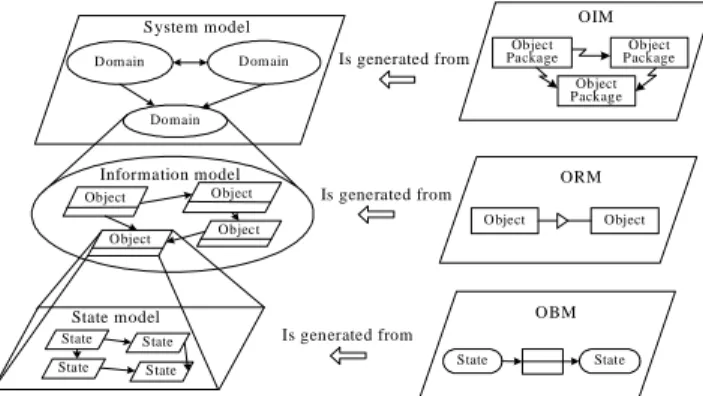
A rectangle represents an object, and the object's variables are shown in the lower rectangle. In CAMP, information is considered and stored in production data and knowledge bases. Systematic information modeling methodology is used in this chapter to analyze and present information on CAMP blackboards.
Summary and Discussions
6.4] Naish, J.C., 1996, "Process capability modeling in a concurrent integrated engineering system - the feature-oriented capability module", Journal of Materials Processing Technology, (6), p. 6.9] Kiritsis, D., 1995, "A review of knowledge-based expert systems for process planning: methods and problems," International Journal of Advanced Manufacturing Technology, 10(4), p. 6.16] Kang, Y., Rong, Y., Yang, J.-C., 2003, “Computer hardware design verification, part 1: framework and modeling; part 2: tolerance analysis; and part 3: stability analysis,” International Journal of Advanced Manufacturing Technology, 21, p.
Scheduling in Holonic Manufacturing Systems
- Introduction
- Background
- Holonic Systems
- Holonic Manufacturing Systems
- Applications of Holonic Manufacturing Systems
- An Approach: the Fabricare Holonic System
- General Description
- Description of Major Holons
- Negotiation Protocol
- A Prototype
- Experiments
It allows the integration of human experts to override the decision of the holonic controller. During its existence, the task holon will negotiate with the source holons the execution of the operations necessary to perform the ordered product. It also has knowledge of its own capabilities (the processing functions the resource is capable of performing (eg drilling)) and the activities performed with specific tasks (ie the resource's agenda).