This led to the establishment of a Masters in Fire Engineering at the University of Canterbury, with one of the core courses being Structural Fire Engineering, now taught by Dr. Abu. M*cold Design bending moment in cold conditions kN.m M*fire Design bending moment in fire conditions kN.m
Objective and Target Audience
The book brings together, from many sources, a large volume of material relating to the fire resistance of building structures. It begins with fundamentals, provides an introduction to fires and fire safety, outlining the important contribution of structural fire resistance to overall fire safety.
Fire Safety
Performance‐based Design
Fundamentals of Performance‐based Design
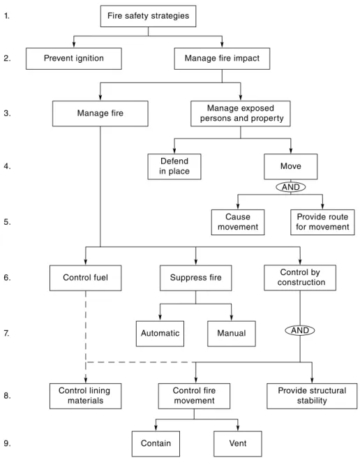
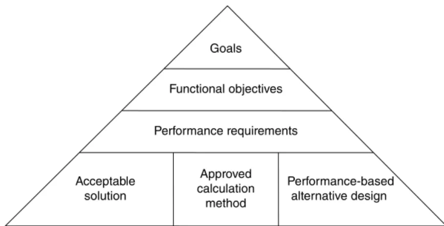
In developing new codes, many countries have adopted a tiered, hierarchical, performance-based code format, as shown in Figure 1.1. For a number of reasons, performance-based fire codes are not easy to create or use; fire safety is part of a complex system of many interrelated variables, there are so many possible strategies that it is not easy to quantitatively assess performance, and they are in short supply.
Documentation and Quality Control
Risk Assessment
The new discipline of structural fire engineering is leading to major advances in testing. This book introduces the fundamentals of structural design for fire conditions and the advantages that structural fire engineering can offer.
Purpose of this Book
Fire resistance is of little importance in the early stages of a fire, but becomes more and more important. The importance of fire resistance depends on the size of the building and fire safety objectives.
Units
To provide life safety, fire resistance is essential in all buildings where a fire can become large before all occupants have time to escape. Fire resistance is also important for firefighters' access and rescue, as firefighters may need to remain in a building for quite some time after all occupants have escaped.
Organization of Chapters
Providing fire resistance is only one part of the overall fire design strategy for protecting occupant life and fire. Fire resistance is also more important for property protection in buildings of any size, especially if the fire is not controlled with a fire suppression system.
Fire Safety Objectives
Life Safety
Environmental Protection
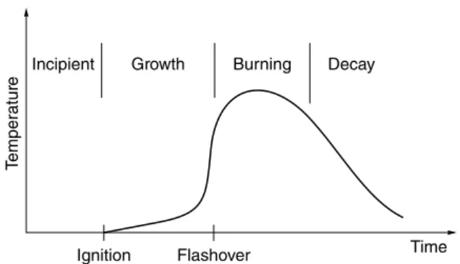
Process of Fire Development
- Fire Behaviour
- Human Behaviour
- Fire Detection
- Active Control
- Passive Control
- Scenario Analysis
- Quantitative Risk Assessment
- Fire Safety Concepts Tree
- Prevention versus Management
- Management of Exposed Persons and Property
- Manage the Fire
- Control by Construction
- Provide Structural Stability
It is the burning period of the fire that mainly impacts on structural elements and compartment boundaries. Structural stability is also essential to protect people or property elsewhere in the building at the time of fire.
Fire Resistance
- Examples of Fire Resistance
- Objectives for Fire Resistance
- Fire Design Time
- Trade‐offs
- Repairability and Reserviceability
To reduce the likelihood of fire spreading to other buildings, boundary walls must have sufficient fire resistance to withstand and contain a fire for the fire design time. To prevent structural collapse, structural elements must be provided with sufficient fire resistance to maintain stability for the fire design time.
Controlling Fire Spread
- Fire Spread within Room of Origin
- Fire Spread to Adjacent Rooms
- Fire Spread to Other Storeys
- Fire Spread to Other Buildings
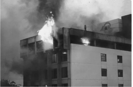
If there are openings in the exterior wall, the likelihood of fire spreading depends largely on the distances between the buildings and the size of the openings. Flaming brands carried by the wind can cause fire spread between buildings with combustible roofing materials as shown in Figure 2.14.
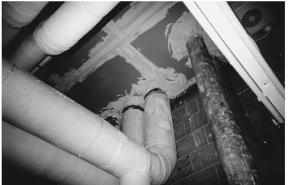
Building Construction for Fire Safety .1 Fire during Construction and Alterations
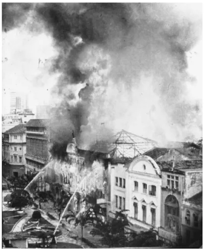
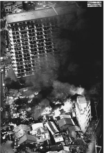
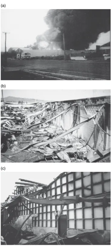
Fire following Earthquake
Major fire damage followed many other earthquakes, including Tokyo in 1923 and Napier, New Zealand in 1931 (Steinbrugge, 1982; Botting, 1998). For these reasons, more attention should be paid to passive containment and structural fire resistance. Figure 2.16 Fire damage after the 1906 San Francisco earthquake.
Assessment and Repair of Fire Damage
Inspection
It is also important to review the fire scene after debris and non-structural items have been removed, when it is possible to inspect the structural parts in more detail. Most members that are deformed during a fire will need to be replaced, unless the deformations do not affect the future use of the building.
Steel
Concrete members that do not show visible damage may have reduced strength due to high concrete or reinforcement temperatures. The loss of strength of concrete itself is usually less of a concern than the loss of strength of steel reinforcement.
Timber
The heat affected zone is often not very thick due to the low thermal conductivity of concrete. Some linings may have fallen off as a result of fire or extinguishing.
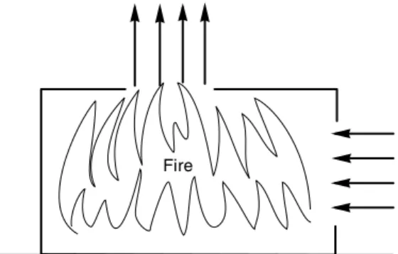
Fires in General
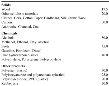
The rate at which heat is released in a combustion reaction depends on the nature of the burning material, the size of the fire and the amount of air available. The single most important descriptor of a fire's intensity is its heat release rate (Babrauskas and Peacock, 1992), which can be calculated as the amount of energy released (MJ) in a given time (in seconds) in units of megawatts (MW). ).
Combustion
Pilot Ignition and Auto‐ignition
Autoignition requires the gases to be at a higher temperature than for pilot ignition. For surfaces exposed to radiant heat flux, the heat flux intensity required to cause autoignition is higher than that required for lead ignition.
Flame Spread
This in turn depends on the size and location of the flame (causing radiative heating), the direction of the air flow (causing convective heating), the thermal properties of the fuel (affecting the rate of temperature rise) and the flammability of the fuel (Drysdale , 2011). Upward flame propagation is always rapid because the flame can preheat the material ahead of the combustion zone.
Pre‐flashover Fires
- Burning Items in Open Air
- Burning Items in Rooms
- t‐Squared Fires
- Fire Spread to Other Items
- Pre‐flashover Fire Calculations
- Zone Models
- Field Models
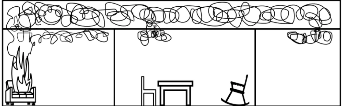
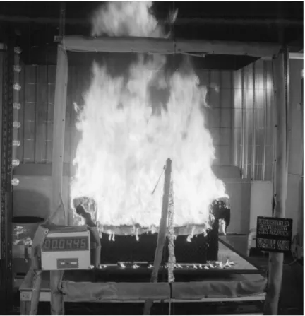
The rate of heat release for burning furniture or other fuel in open air has been discussed in the previous section. Values for k and maximum heat release rate for many different burning objects are given. Figure 3.4 Smoke damage after a pre-flashover fire in a room, indicating the thickness of the hot upper layer below the fire.
Flashover
Conditions Necessary for Flashover
One of the most versatile and widely used zone models is CFAST (Peacock et al., 1993; . Portier et al., 1996) which can calculate the movement of smoke and hot gases in contiguous spaces. CFAST is available free on the Internet from the Building and Fire Research Laboratory of the National Institute of Standards and Technology (NIST).
Post‐flashover Fires
- Ventilation Controlled Burning
- Rate of Burning
- Ventilation Factor
- Multiple Openings
- Fuel Controlled Burning
- Fire Temperatures
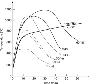
- Measured Temperatures
- Swedish Curves
- Rate of Temperature Decay
- Computer Models
- Swedish Method and Lie’s Method
The interactions depend on the form of the fuel (crab or lining materials), the fuel itself (wood or plastic or liquid fuel) and the vents. W is the length of the long side of the width of the room (m), D is the length of the short side of the room (m), and At is the total area of the interior surfaces of the room (m2).
Design Fires
Hand Methods
COMPF2 was a one-zone model that solved the heat balance equations to generate gas temperatures. Ozone is a single-zone model developed in Europe as part of a large collaboration investigating the 'natural fire safety concept' for the competitive design of steel buildings (Cadorin et al., 2001).
Published Curves
The hydrocarbon fire curve is used for environments where there is a high degree of hydrocarbons.
Eurocode Parametric Fires
- Duration of Burning Period
- Decay Period
The above formulation of the parametric fire curve assumes that the walls and ceiling of the fire section are made of one layer of material with thermal inertia k ρ cp. The Eurocode time-temperature relationship in the cooling phase of the parametric fire is given by: 3.30a).
Other Factors
Additional Ventilation Openings
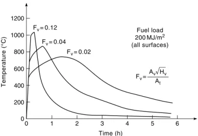
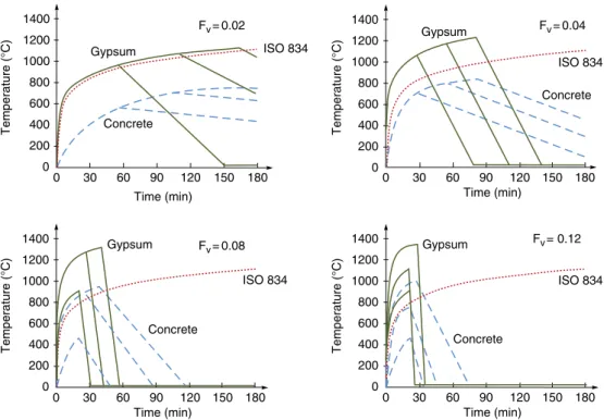
It is observed that with the exception of the fire in the plaster-clad room and a fuel load of 400 MJ/m2, the fires with opening factors of 0.02 and 0.04 have the same general form of concrete or plaster. The different falling branch is due to the fact that t*max for the 400 MJ/m2 case lies between 0.5 hours and 2 hours, while the rest have t*max values greater than 2 hours.
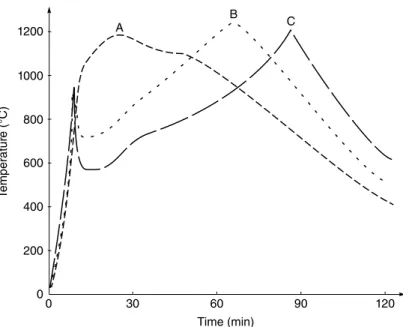
Progressive Burning
Even when the fire started at the end farthest from the window, the burn quickly moved to the bottom of the window, then slowly progressed from that end toward the back as shown in Figure 3.24. The temperatures measured at points A, B and C in figure 3.24 are presented in figure 3.25 where it can be seen that the total duration of
Localized Fires
Heat Transfer
- Conduction
- Simple Formulae
- Numerical Analysis
- Convection
- Radiation
- Design Charts for Fire Resistance Calculation
- Worked Example 3.2
- Worked Example 3.3
- Worked Example 3.4
- Worked Example 3.6
- Worked Example 3.7
- Worked Example 3.8
- Worked Example 3.10
- Worked Example 3.11
- Worked Example 3.12
- Worked Example 3.13
Calculate the ventilation-controlled heat release rate and duration of combustion for the room from the previous examples, using Law's equation. Calculate the convective heat transfer coefficient on the cool side of the wall if the ambient temperature is 20 °C and all the heat passing through the wall is dissipated by convection.
Providing Fire Resistance .1 Background
- Time domain
- Temperature domain
- Strength domain
- Example
- Fire Exposure Models
- Design Combinations
Verification in the strength domain is a comparison of the applied load at the time of the fire with the load-bearing capacity of structural members during the fire, such that. The loads at the time of the fire can be calculated using load combinations from the national tax codes.
Fire Severity
In general, both the accuracy of the prediction and the amount of computational effort increase downwards in the table. Therefore, the severity of the fire largely depends on the temperatures reached and the duration of the high temperatures.
Equivalent Fire Severity
- Equal Area Concept
- Maximum Temperature Concept
- Minimum Load Capacity Concept
- Time Equivalent Formulae
- CIB Formula
- Law Formula
- Eurocode Formula
- Validity
In a similar concept based on load capacity, the equivalent fire severity is the time of exposure to the standard fire that will result in the same carrying capacity as the minimum that would occur in a complete burnout of the fire cell. Af is the floor area of the compartment (m2), Av is the area of vertical openings in the walls (m2) and Ah is the area of horizontal openings in the roof (m2).
Fire Resistance .1 Definition
Assessing Fire Resistance
The fire resistance of any building element depends on many factors, including the severity of the fire test, the material, the geometry and support conditions of the element, restraint of the surrounding structure and the applied loads at the time of the fire. Many building codes and manufacturers' documents simply list fire resistance ratings of 1, 2, or 4 hours with little or no reference to these factors discussed further in this book.
Fire Resistance Tests
- Standards
- Failure Criteria
- Furnace Pressure
- Applied Loads
- Restraint and Continuity
The burners are ignited at the start of the test and controlled to produce the time -. The essential temperature measurements are those in the furnace itself and on the unexposed face of the sample.
Specifying Fire Resistance
Approved Fire Resistance Ratings
- Listings
- Generic Ratings
- Proprietary Ratings
- Calculation Methods
- Expert Opinion
Calculation methods should be verified by full-scale fire resistance test results of similar assemblies. Most of the lists described in the above documents are based directly on the results of full-scale fire resistance tests.
Fire Resistance by Calculation
- Fire Model
- Heat Transfer Model
- Structural Model
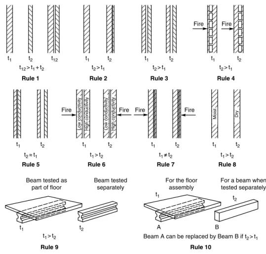
As an indication of the factors to be considered in forming an opinion, Figure 4.9 illustrates a useful set of empirical 'rules' for comparing fire resistance of similar assemblies (Harmathy, 1965). The heat transfer model is an essential component of the calculation of fire resistance because the load capacity or the containment capacity of a fire exposed element or structure depends on the internal temperatures.
Fire Resistance of Assemblies
- Walls
- Floors
- Beams
- Columns
- Penetrations
- Junctions and Gaps
- Seismic Gaps
- Fire Doors
- Ducts
- Glass
- Historical Buildings
- Worked Example 4.2
- Worked Example 4.3
The fire resistance of all these must be considered as part of the fire safety design. An air handling duct that passes through a barrier can cause a serious reduction in the fire resistance of the barrier.
Structural Design at Normal Temperatures
To avoid the collapse of a building structure, the combination of elements and their supporting parts must perform their load-bearing function during the duration of the fire. In many simple structures, the collapse of one member can result in total collapse of the structure.
Loads
- Types of Load
- Load Combinations
- Structural Analysis
- Non‐linear Analysis
- Design Format
- Working Stress Design Format
- Material Properties
- Probability of Failure
The dead load is the self-weight of the structure estimated by the designer, and the live loads are specified by national design codes. In Figure 5.2, the solid line shows the behavior parallel to the grain where the tensile strength is very high, and the dotted line shows the behavior perpendicular to the grain where the tensile strength is very poor (separation failure).
Structural Design in Fire Conditions
Design Equation
Verification of design for strength during fire requires that the applied loads be less than the bearing capacity of the structure, for the duration of the fire design time. Fire design is based on the most likely expected strength, so most national and international codes specify a strength reduction factor of Φfire = 1.0.
Loads for Fire Design
- Load Combinations
- Working Stress Design
Most modern load codes, which specify load combinations for fire design, are in limit states (LRFD) format with loads similar to those described above. Load codes in the working voltage format typically do not include load combinations for fire design, so designers must use the normal temperature design load combination of Lw G Q for fire design, which is very conservative as it does not recognize the probable reduction of loads. in an unexpected fire.
Structural Analysis for Fire Design
The load ratio is much less than 0.5 for buildings or parts of buildings designed to withstand extreme events such as rare blizzards, hurricanes or earthquakes. The lower the load ratio, the greater the fire resistance, due to the large loss of load-bearing capacity that can occur before collapse in a fire.
Material Properties in Fire
Testing Regimes
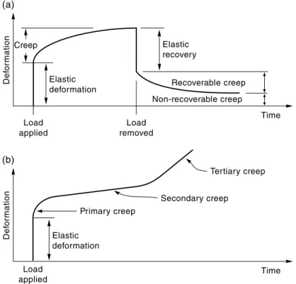
For most materials, stress-strain relationships at elevated temperatures can be obtained directly from steady-state tests at certain elevated temperatures (regime 1), or they can be derived from the results of transient tests. Anderberg (1988) compares stress-strain relations obtained in both ways and points out that there are differences due to the effect of creep.
Components of Strain
- Stress‐related Strain
- Thermal Strain
- Creep Strain
- Transient Strain
- Effect of Strain Components
Stress-related deformation (or mechanical deformation) refers to deformation that causes stresses in structural members. These stresses are based on the stress-strain relationships shown in Figure 5.2, which are used for the structural design of all materials.
Design of Individual Members Exposed to Fire
- Tension Members
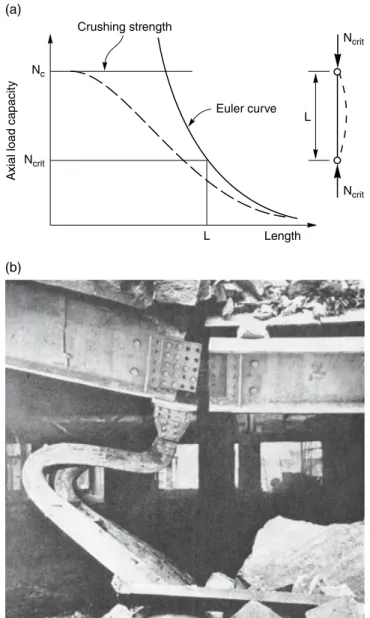
- Compression Members
- Beams
- Flexural Design
- Lateral Buckling of Beams
- Shear Design
- Redundancy
- Disproportionate Collapse
- Continuity
- Continuous Beams
- Moment Redistribution
- Plastic Design
- Axial Restraint
- Effect of Restraint on Heated Members
- Code Requirements for Restraint
- After‐fire Stability
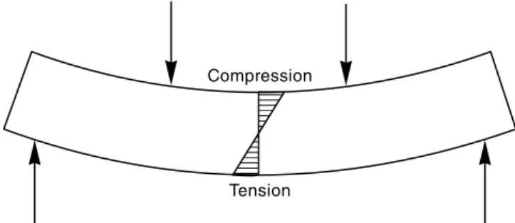
A negative bending moment is a moment that causes stress at the top of the beam (a hogging moment). An axial restraining force near the top of the beam, as shown in Figure 5.20(a), would result in.
Worked Examples .1 Worked Example 5.1
Worked Example 5.2
Assuming that the plate has equal positive and negative bending capacity, the load ratio is calculated taking into account redistribution to equal positive and negative moments. However, with redistribution, the bending moment diagram can take any position, provided that the sum of positive and negative moments remains at w Lf 2/8 4 90.
Worked Example 5.3
Final failure of the plate is not expected until its strength under fire conditions is reduced to 33% of its strength at normal temperatures. Failure of the slab is not expected until its cantilever strength under fire conditions has been reduced to 65% of its strength at normal temperatures and the midspan strength has dropped to zero.
Worked Example 5.4
In this case, the plate could survive a fire, although the positive bending capacity at the center. This chapter contains the information needed to calculate the performance of steel buildings exposed to fire.
Behaviour of Steel Structures in Fire
Structural Steel Design Process
First, the traditional method of using fire resistance ratings in the time domain is described. The required fire resistance can then be compared with the fire resistance degree of the selected assembly.
Steel Temperature Prediction .1 Fire Exposure
- Calculation Methods
- Section Factor
- Thermal Properties
- Temperature Calculation for Unprotected Steelwork
- Eurocode Method
- Temperature Calculation for Protected Steelwork
- Eurocode Method
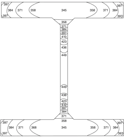
- Typical Steel Temperatures
- Temperature Calculation for External Steelwork
Here F is the area of the length unit of the member (m2), V is the volume of steel in length unit of the member (m3), Hp is the heated circumference of the cross section (m), A is the cross- . Thus calculated, the section factor for a steel plate exposed to a fire on both sides is V/F = t/2 where t is the thickness of the plate.
Protection Systems
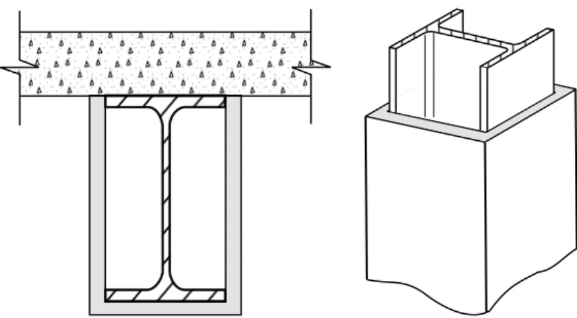
- Concrete Encasement
- Board Systems
- Spray‐on Systems
- Intumescent Paint
- Protection with Timber
- Concrete Filling
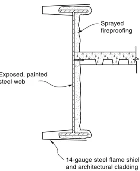
- Flame Shields
Spray-on proprietary protection is typically the least expensive form of passive fire protection for steel elements. Test methods are available for testing the consistency and adhesion of spray-on fire protection (ICC, 2015).
Mechanical Properties of Steel at Elevated Temperature
- Components of Strain
- Thermal Strain
- Creep Strain
- Stress‐related Strain
- Proof Strength and Yield Strength
- Design Values
- Modulus of Elasticity
- Residual Stresses
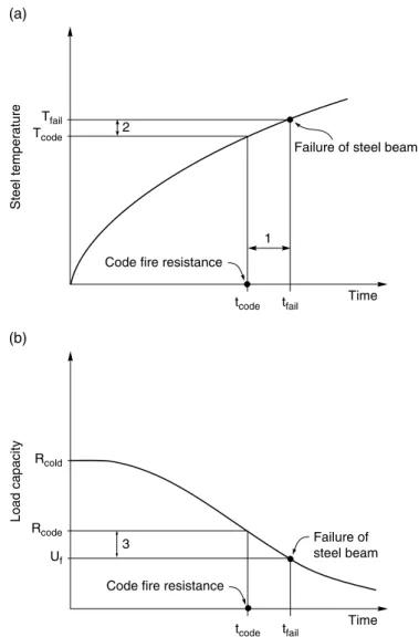
Typical stress-strain relationships for structural steel at high temperatures are shown in Figure 6.15, where it can be seen that the yield strength and modulus of elasticity decrease with increasing temperature, but the ultimate tensile strength increases slightly at moderate temperatures before decreases at higher temperatures. Most normal construction steels have a very well-defined yield strength at normal temperatures, but this disappears at high temperatures, as shown in Figure 6.15.
Design of Steel Members Exposed to Fire .1 Design Methods
Verification