Finally, I would like to thank my parents, brother, relatives and friends for their love, compassion and strength. Our TPDV technique will facilitate the study of deformation and failure of materials during normal and compressive-shear plate impact.
INTRODUCTION
The impact of the kite on the target generates a pressure wave that propagates within both plates. This technique, called the normal displacement interferometer (NDI), uses the back of the target plate as a mirror of the Michelson interferometer (Figure 1.3).

THEORY
Classical Waves WaveformsWaveforms
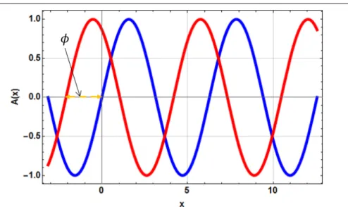
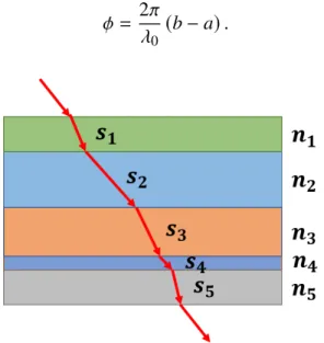
Alternative forms of (2.1) are constructed using water f,. 2.8) A wave's phase information Φ incorporates both space and time information to represent the wave's position in its cycle. The normals to the planes are parallel to the direction of propagation of the wave or wave vector, k.
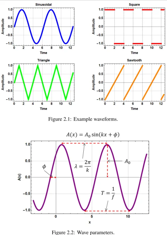
Plate Impact: Elastic Waves and Materials Plate Impact SystemPlate Impact System
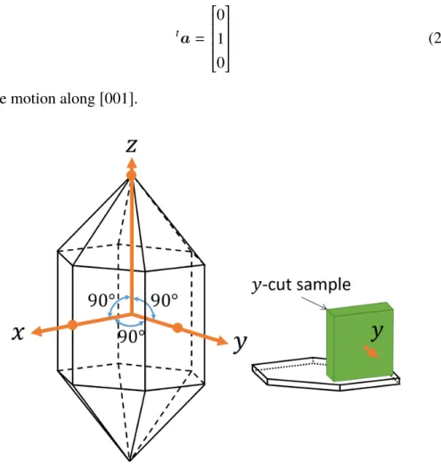
Furthermore, the continuity of displacements at the impact interface ensures that the flyer and the target plate remain in contact. The wave speed and polarization directions of the isotropic flyer and trigonal target plates from (2.78) and (2.80) are used to solve for the free surface velocity of the back of the trigonal target plate (Section 2.2).

Interferometry: Electromagnetic Waves and Light Photonic Doppler Velocimetry SystemPhotonic Doppler Velocimetry System
At least two of the three probes must function to determine the motion of the target in three dimensions. Light transmitted to the diffraction grating on the back surface of the objective with normal incidence will reflect and diffract from the back of the objective according to the diffraction equation. The radiation of combined electric fields (2.92) gives the two-ray formula for the combined wave intensity.
The first time derivative of the interference phase information Φ?, represents the rate of change of the mixed light's phase, or the angular frequency of the interfered light. Three probes The diffraction equation (2.87) gives the angles θ±n of the ±nth rays deflecting from the target's grating. Calculation of the phase information of the oscillating intensity (2.95) of the normal beam mixed with reference light yields.
Applying θ±n to (2.90) gives the phase shift of the reflected light. 2.108) Calculation of the phase information of the oscillation intensity (2.95) of the corresponding beams mixed with the yields of the reference light. The frequencies of the diffracted target beams can be found by analyzing the signal recorded by the oscilloscope and give the uncoupled longitudinal and transverse movements of the target.
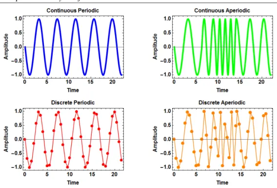
Spectral Analysis of Waves Fourier TransformsFourier Transforms
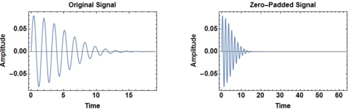
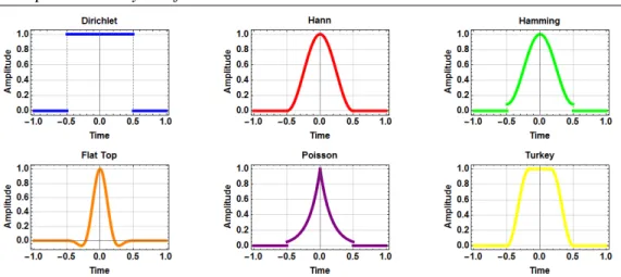
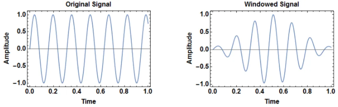
Zero padding involves adding a string of zeros to the end of the time series signal, which increases the length of the signal to Nf f t without adding additional information (Figure 2.15). Short-time sliding Fourier transform (STFT) The DFT gives the frequency content of the signal in the entire time domain of the signal t ∈ [t0,tN−1]. Window methods The precision and accuracy of the STFT depends on the choice of the window function in the time window τ (Figure 2.17) [47].
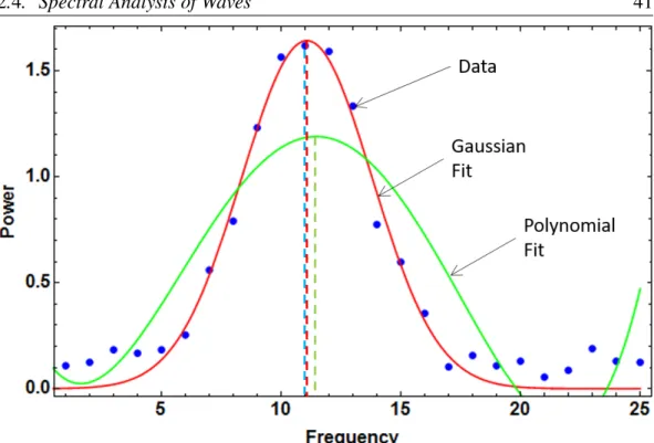
This tightening of the signal at the edges reduces the phenomenon of spectral leakage by reducing the marginal discontinuities. Removing the boundary discontinuities makes the signal periodic in time, which is an assumption of the Fourier transform. The PSD of a continuous signal f(t) in the frequency domain is calculated from. 2.135) These coefficients are now used to calculate the PSD of each frequency of the continuous signal.
Finding the maximum of the data points limits the returned maximum to one of the points in the dataset. This carrier frequency shifts the frequency content of the underlying signal to achieve full fringes for window sizes shorter than the period of the signal (Figure 2.21).
Specimen Preparation MaterialsMaterials
This ensured that the flyer plate would not fail before the target plate failed, and that the impact interface could sustain a sufficient amount of shear stress. The thickness of the flyer plate was chosen such that wave reflections from the back of the flyer plate would not reach the impact interface before separation. The values for the material constants of borosilicate, given in Table (3.4), are taken from Schott North America mechanical property data sheets [54].
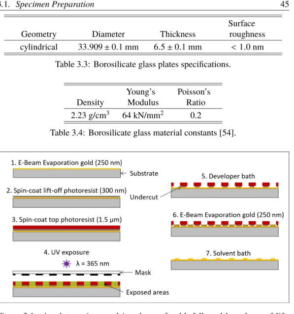
A diffraction grating was created on the back of the target plate as part of the TPDV system. The grating is designed according to reference [55] and fabricated according to reference [56] with the materials specified in table (3.5) (Figure 3.1). Another layer of gold is deposited and the remainder of the photoresist is removed in a solvent bath.
The quartz plates were coated with a thin layer of metal and a thin layer of gold using physical vapor deposition in a clean room environment. The upper plateaus are the top of the grid and the lower plateaus are the gold plating.
Interferometer Construction Optical ConfigurationOptical Configuration
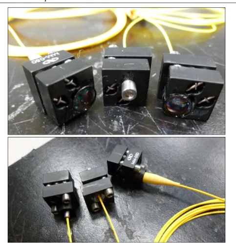
Each beam is carried by SM cables and FC/APCs to a three-port optical circulator manufactured by Agiltron. The PDV probe is a pigtail-style collimator for 1550 nm with a 1.4 mm aspherical lens manufactured by OZ Optics. The two TPDV probes are pigtail-style collimators to 1550 nm with a 6.2 mm aspherical lens manufactured by OZ Optics.
The laser light is transmitted via SM cables and FC/APC connectors to a 50/50 optical fiber coupler/splitter manufactured by Agiltron. Each beam is carried by SM and FC/APC cables to variable fiber optic attenuators manufactured by OZ Optics. SM and FC/APC cables carry each channel to one of two Agiltron manufactured 50/50 single-ended fiber optic couplers/splitters.
The active PDV probe is a pigtail-style collimator to 1550 nm with a 1.4 mm aspherical lens manufactured by OZ Optics. The two passive TPDV probes are pigtail-style collimators to 1550 nm with a 6.2 mm aspherical lens manufactured by OZ Optics.
Powder Gun Implementation Powder Gun OverviewPowder Gun Overview
Once the fit is checked, the airfoil is epoxied in place with Gorilla two-part epoxy (Figure 3.15). Once the yields are maximized, Gorilla two-part epoxy is placed over the tops and sides of the probes to hold them in place (Figure 3.18). The shorting pins are then pushed into the sample holder so that they are aligned with the top of the target plate and flush with the mirror surface (Figure 3.20).
An MRA-50 Autocollimator manufactured by Micro-Radian Instruments is used to analyze light reflected by a prism from rubber-banded mirrors bonded to the impact surface of the kite and target plates (Figure 3.23). The holes in the flame splitter are covered with masking tape to prevent gunpowder from spilling into the holes (Figure 3.26). The flame distributor assembly is screwed onto the lock piece door and slid into the lock piece (Figure 3.27).
A magnetic release device manufactured by Guardian Electric is fitted to the rear of the brake (Figure 3.28). The red trigger button is pressed on the trigger box to run the experiment (Figure 3.29).
RESULTS
Signal
Free Surface Velocity SpectrogramSpectrogram
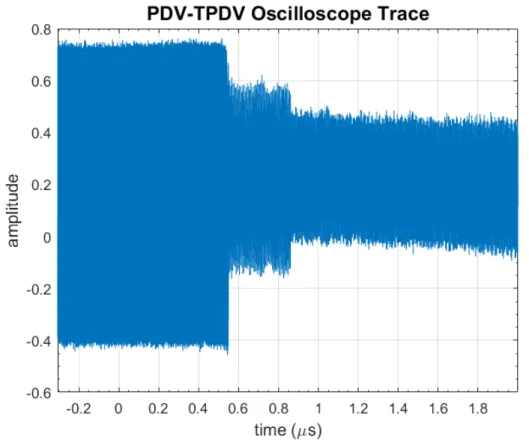
Filtering prevents the lower band from bridging and interfering with the identification of the dominant frequency that caused the longitudinal shift in the upper band. However, when the surface of the target plate moved, the amount of light received by the TPDV probe decreased faster than that of the PDV probe. The QL wave reaches the rear of the target in about 0.54 µs, and the QT wave reaches the rear of the target in about 0.86 µs.
The spike in transverse velocity on the rising edge is thought to be caused by a mismatch in the time lengths of the longitudinal and transverse transient regions. In addition, the arrival times of the QL wave around 0.54 µs and the QT wave around 0.86 µs do not match the respective predicted arrival times of 0.83 µs and 1.16 µs. Therefore, the arrival time of the QL wave on the TPDV spectrogram does not exactly match the PDV spectrogram.
Furthermore, because the transverse velocity has larger fluctuations around its mean than that of the longitudinal velocity, a higher TPDV uncertainty is expected. Lower amounts of light reflection are reflected in the power of the TPDV spectrogram compared to the PDV spectrogram.
Impact Conditions TiltTilt
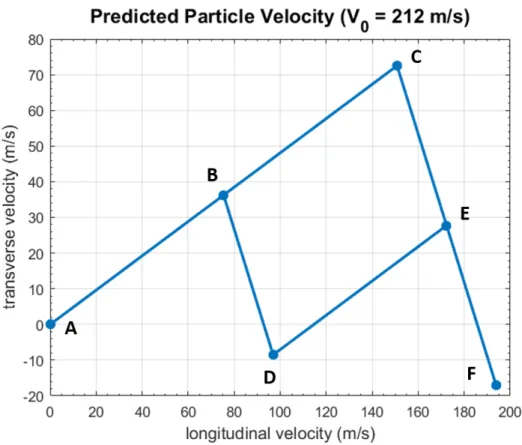
The longitudinal velocity of the free surface jumps to 150.79 m/s at the arrival of the QL wave and again to 193.84 m/s at the arrival of the QT wave. The transverse velocity of the free surface jumps to 72.51 m/s at the arrival of the QL wave and again to −17.02 m/s at the arrival of the QT wave. The normal grip jumps to −1.2 GPa at the arrival of the QL wave and again to −1.45 GPa at the arrival of the QT wave.
The shear pull jumps to −0.58 GPa at the arrival of the QL wave and again to −0.066 GPa at the arrival of the QT wave. Since the free surface velocity of the target plate is proportional to the QL and QT waves. Specifically, the QL wave arrival spike deviated by 1.7° and the QT wave arrival spike by 1.6°.
The jump in normal tractionσy y and shear traction σyz associated with the QL wave is. Specifically, the QL wave's polarization vector deviated by 1.7° and the QT wave's polarization vector deviated by 0.1°.
CONCLUSION
This would streamline sample preparation as there would be no need to deposit a thin reflective coating on the back of the target. Moreover, similar to the PDV technique, the sensitivity of the TPDV technique can be increased using 1064 nm probing light [65]. Improving the accuracy, precision and time resolution of displacement measurement techniques is critical for characterizing the properties of materials undergoing impact loading.
For example, interfaces in fibrous and multilayer composites used for spacecraft disperse shock waves and the compressive strength of concrete used for bunkers increases at high strain rates [66–68]. Shock waves are used in explosive welding to join metals, synthesize diamonds and blast rock for mining operations. For example, how seismic events such as earthquakes disrupt the Earth's surface [69], how meteorite impacts cause ground motion [70], and how meteorite impacts cause metamorphosis of minerals in crater geology [71].
These applications of shock waves in research and industry, and natural shock events, are evidence that shock waves play an integral role in our world. They dictate how light and sound interact with matter, and how light, sound and matter change in space and time.
BIBLIOGRAPHY
Dynamic yield behavior of explosively stressed metals determined by a quartz transducer technique. Journal of Applied Physics. An optical absorption study of the origin of color and pleochroism in pink and brown tourmalines. Driscoll, K. Understanding quartz technology in early prehistoric IrelandPhD thesis (University College Dublin, 2010).https://library.ucd.ie/iii/.
Shock Propagation Produced by Planar Impact in Linearly Elastic Anisotropic Media.Journal of Applied Physics. Shock-induced overheating and melting curves of geophysically important minerals. The physics of the Earth and the interior of the planets. On the use of windows for harmonic analysis with the discrete Fourier transform. Proceedings of the IEEE.
Experimental investigation of shock wave propagation in periodically layered composites. Journal of the Mechanics and Physics of Solids. Source properties of the 1997-98 central Italy earthquake sequence from inversion of long-period and broadband seismograms. Journal of Seismology.
EBSD TEXTURE ANALYSIS
SOLID WORKS DRAWINGS
![Figure 1.3: In a Normal Displacement Interferometer, the target plate serves as a mirror of the Michelson’s interferometer [12].](https://thumb-ap.123doks.com/thumbv2/123dok/11220308.0/14.918.241.665.117.592/figure-normal-displacement-interferometer-target-serves-michelson-interferometer.webp)
![Figure 1.4: A Transverse Displacement Interferometer captures diffracted beams that contain transverse displacement information [30].](https://thumb-ap.123doks.com/thumbv2/123dok/11220308.0/16.918.173.743.112.836/transverse-displacement-interferometer-captures-diffracted-transverse-displacement-information.webp)