Upscaling Immiscible Two-Phase Flows in an Adaptive Frame
Thesis by
Theofilos Strinopoulos
In Partial Fulfillment of the Requirements for the Degree of
Doctor of Philosophy
California Institute of Technology Pasadena, California
2005
(Defended November 30, 2005)
c 2005
Theofilos Strinopoulos All Rights Reserved
To Thanos.
I could only run this far because you tied my shoe laces.
Acknowledgements
I want to thank my advisor Professor Thomas Hou for the opportunity to work with him. This thesis acquires more meaning within the context of the rest of his research because all his projects revolve around the same ideas and shed light to them from different angles. I admire his vision of complete understanding that he strives for and it has been a pleasure to see this understanding slowly be revealed. I want to thank him also for his guidance during these years and his patience with my many shortcomings. He constantly raised the standards and pushed me towards excellence.
Professor Yalchin Efendiev contributed his mathematical insights and experience with the two-phase flow equations. His energy drove this thesis to completion. He oversaw large parts of the my efforts and was always available to discuss and answer my questions. In the days I spent in Texas with him, we resolved some key theoret- ical points of this work. I enjoyed working with him and am glad that he and his collaborators will continue this work.
Professor Ruo Li helped me with the design of the moving mesh. Professor Dan- ping Yang helped me understand the projection operator in Andy Westhead’s thesis.
I enjoyed speaking the universal language of mathematics with him.
I want to thank the members of my committee Professors Oscar Bruno, Niles Pierce and Dale Pullin for their suggestions.
It has been a pleasure to share this adventure with the people in the Applied Mathematics Department. I want to thank my classmates Gaby Stredie, Andy West- head, Lei Zhang, Wuan Luo, Xinwei Yu, Marco Latini, Stephane Lintner, David Hoch for their company, our discussions. Danny Petrasek and Alexei Novikov are another two people whose company and advice I seeked often. I thank Sheila and Chad for keeping the gods of bureaucracy and computers at bay.
My first advisor, Professor Thanos Tzavaras inspired me to undertake this journey.
I admire his quality as a person, which I prefer not to divide into words and his love for applied mathematics.
What gave meaning to this journey and the most important thing I take from it are the people I met. My co-protagonists in this colorful drama of success and failure, loneliness and companionship, competition and comraderie, miscommunication and genuine exchange. The curtain has fallen and some of their names appear: Orestis Raptis, Savvas Koudounas, Manos Fitrakis, George Mathaiou, Endy Min, Roger Re- villa, Serena Guarnaschelli, Joseph Tsidulko, Sarah Farivar, Dave Michalak, Lavanya Reddy.
Abstract
We derive the two-scale limit of a linear or nonlinear saturation equation with a flow-based coordinate transformation. This transformation consists of the pressure and the streamfunction. In this framework the saturation equation is decoupled to a family of one-dimensional nonconservative transport equations along streamlines.
This simplifies the derivation of the two-scale limit. Moreover it allows us to obtain the convergence independent of the assumptions of periodicity and scale separation.
We provide a rigorous estimate on the convergence rate. We combine the two-scale limit with Tartar’s method to complete the homogenization.
To design an efficient numerical method, we use an averaging approach across the streamlines on the two-scale limit equations. The resulting numerical method for the saturation has all the advantages in terms of adaptivity that methods have. We couple it with a moving mesh along the streamlines to resolve the shock more efficiently. We use the multiscale finite element method to upscale the pressure equation because it gives access to the fine scale velocity, which enters in the saturation equation, through the basis functions. We propose to solve the pressure equation in the coordinate frame of the initial pressure and saturation, which is similar to the modified multiscale finite element method.
We test our numerical method in realistic permeability fields, such as the Tenth SPE Comparative Solution Project permeabilities, for accuracy and computational cost.
Contents
Acknowledgements . . . iv
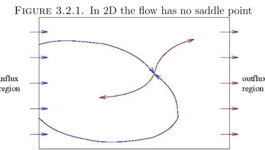
Abstract . . . vi
List of Figures . . . x
List of Tables . . . xii
Notation . . . xiii
Chapter 1. Introduction . . . 1
Part 1. Resolved Scheme . . . 8
Chapter 2. The Porous Media Equations in the Cartesian Frame . . . 10
2.1. Derivation of the Physical Model . . . 10
2.1.1. Pressure Equation . . . 13
2.1.2. Saturation Equation . . . 15
2.1.3. Model Problem . . . 17
2.2. Resolved Scheme . . . 19
2.2.1. Finite Volume Method for the Pressure equation . . . 19
2.2.2. Finite Volume Method for the Saturation Equation . . . 20
2.3. Some Numerical Results . . . 21
Chapter 3. An Adaptive Framework for Solving the Porous Media Equation 24 3.1. Context of the Present Work . . . 24
3.2. The Pressure-Streamline Frame . . . 25
3.2.1. Coordinate Transformation . . . 25
3.2.2. Entropy Solutions . . . 26
3.2.3. Invertibility . . . 29
3.2.4. Adaptivity . . . 30
Adaptivity across the streamlines . . . 30
Adaptivity along the streamlines . . . 33
Adaptivity in time . . . 36
3.2.5. Extension to Three Dimensions . . . 36
3.3. Numerical Implementation . . . 37
3.3.1. Computing Ψ,v0 . . . 37
3.3.2. Natural Neighbor Coordinates . . . 38
3.3.3. Finite Volume Scheme for the Saturation in p, ψ . . . 40
3.3.4. Moving Mesh . . . 43
3.4. Numerical Results . . . 48
Part 2. Upscaled Scheme . . . 51
Chapter 4. Upscaling One-Phase Flow . . . 53
4.1. Two-Scale Limit . . . 53
4.1.1. Context of the Present Work . . . 53
4.1.2. Derivation of the Two-Scale Limit for Linear Flux . . . 57
4.1.3. Derivation of the Two-Scale Limit for Nonlinear Flux . . . 61
4.1.4. Convergence Rate to the Two-Scale Limit . . . 65
4.2. Comparison with the Cell Problem in the Cartesian Frame . . . 71
4.3. Weak Limit and Full Homogenization . . . 73
4.4. Designing an Upscaled Model from the Two-Scale limit . . . 74
4.4.1. Physical Interpretation of the Subgrid Forcing . . . 75
4.4.2. Numerical Averaging across Streamlines for Linear Flux . . . 76
4.4.3. Numerical Averaging across Streamlines for Nonlinear Flux . . . 77
4.5. Implementation . . . 79
4.5.1. Considerations for the Macrodispersion . . . 79
4.6. Numerical Results . . . 80
4.6.1. Macrodispersion Modeling. . . 81
4.6.2. Saturation Snapshots . . . 82
4.6.3. Accuracy and Computational Cost . . . 92
Chapter 5. Upscaling Two-Phase Flows . . . 96
5.1. Pressure Equation . . . 96
5.1.1. The Multiscale Finite Element Method (MSFEM) . . . 96
5.1.2. The Modified MSFEM . . . 98
5.1.3. The Modified MSFEM in the Pressure-Streamline Frame . . . 98
5.1.4. Derivation of the Equations . . . 100
5.2. Implementation . . . 102
5.2.1. Computing the Pressure with MSFEM . . . 102
5.2.2. Computing the Streamfunction . . . 104
With the Multiscale Finite Volume Method (MSFVM) . . . 104
With an Elliptic Equation . . . 104
5.2.3. Coarse Interpolation . . . 105
5.3. Numerical Results . . . 106
5.3.1. The TransformationP0,Ψ0 →P,Ψ . . . 106
5.3.2. Upscaling Only the Pressure . . . 107
5.3.3. Full Upscaling . . . 108
Chapter 6. Conclusion and Future Directions . . . 111
Bibliography . . . 113
Appendix . . . 117
Proof that fSSp depends weakly on time . . . 117
Index . . . 119
List of Figures
1.0.1 A porous rock . . . 2
2.2.1 Staggered grid for the pressure . . . 19
2.3.1 Shock and rarefaction of the Buckey Leverett equation . . . 22
2.3.2 Fingering in two phase flows . . . 23
3.2.1 In 2D the flow has no saddle point . . . 30
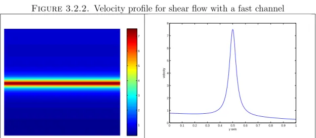
3.2.2 Velocity profile for shear flow with a fast channel . . . 31
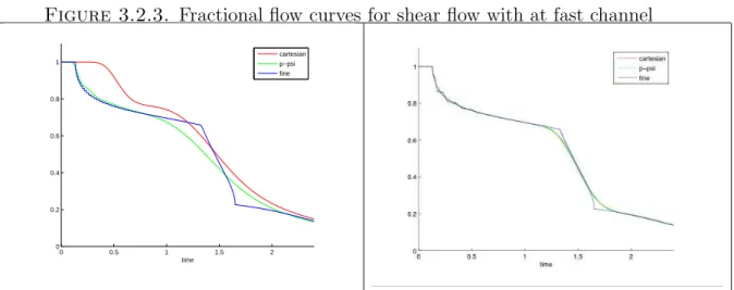
3.2.3 Fractional flow curves for shear flow with at fast channel . . . 32
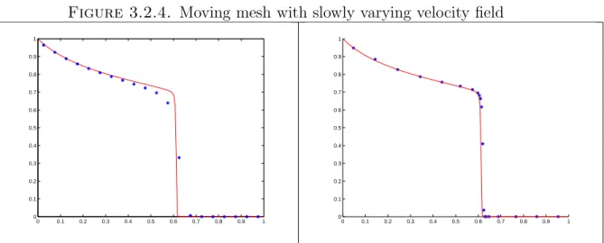
3.2.4 Moving mesh with slowly varying velocity field . . . 34
3.2.5 The mesh transformation . . . 35
3.2.6 Moving mesh with rapidly varying velocity field . . . 35
3.3.1 Interpolation weights for natural neighbor coordinates . . . 39
3.4.1 2pt geostatistics permeability field . . . 48
3.4.2 Numerical diffusion in the presence of fast channels . . . 49
3.4.3 With a fine grid numerical diffusion is decreased . . . 50
3.4.4 Convergence rate of the fine Cartesian and pressure-streamline methods 50 4.1.1 Velocity is smoother in p, ψ frame . . . 56
4.1.2 Fine and coarse characteristics intersect at the boundaries of the cells . . 67
4.6.1 One-phase flow, linear flux, 2pt geostatistics snapshots . . . 82
4.6.2 Saturation snapshots for a layered permeability field, linear flux . . . 84 4.6.3 Saturation snapshots for the percolation case (Stanford 44), linear flux . 85
4.6.4 Saturation snapshots for a fast channel (SPE10 36), linear flux . . . 86
4.6.5 Saturation snapshots for a layered permeability field, nonlinear flux . . . 87
4.6.6 Saturation snapshots for the percolation case (Stanford 44), nonlinear flux 88 4.6.7 Saturation snapshots for a fast channel (SPE10 36), nonlinear flux . . . 89
4.6.8 Saturation snapshots with decreasing coarse block size . . . 90
4.6.9 Fractional flow rates with decreasing coarse block size . . . 91
5.1.1 Boundary conditions for the cells of the pressure equation . . . 100
5.1.2 The Multiscale Streamline Method . . . 103
5.2.1 Coarse and fine grids for the MSFVM Method . . . 103
5.3.1 Cartesian and P0,Ψ0 coordinate transformations . . . 106 5.3.2 Numerical diffusion in Cartesian andP0,Ψ0 coordinate transformations 107 5.3.3 Snapshots for the full upscalling method for a layered permeability field 109
List of Tables
1 2nd order convergence of fine p, ψ scheme . . . 42
2 1st order convergence of fine p, ψ scheme near extrema . . . 42
3 Order of accuracy of finep, ψ scheme in the presence of shocks . . . 43
4 Order of accuracy ofp, ψ scheme with moving mesh . . . 47
5 Efficiency of moving mesh for linear flux . . . 47
6 Efficiency of moving mesh for nonlinear flux . . . 48
7 L1 error of fine pressure-streamline method . . . 49
1 Numerical demonstration of theorem 4.1.8 . . . 80
2 Upscaling error for the layered permeability . . . 92
3 Upscaling error for the percolation case (Stanford 44) . . . 92
4 Upscaling error for the fast channel (SPE10 36) . . . 92
5 Total error for the layered permeability . . . 93
6 Total error for the percolation case (Stanford 44) . . . 93
7 Total error for the fast channel (SPE10 36) . . . 94
8 Computational cost . . . 94
9 Comparison to a naive upscaling method for SPE10 36 . . . 95
1 Pressure upscaling error for the layered permeability . . . 108
2 Convergence of the full upscaling method for the layered permeability . . . 110
3 Comparison to a Cartesian upscaling method . . . 110
Notation
Bold letters indicate vectors or matrices, normal letters indicate scalars. For the quantities that define the coordinate transformations a capital letter denotes a function and a lowercase letter denotes a spatial variable. For P, p,Ψ, ψ,v a zero subscript indicates the quantity at t = 0. A ˜· denotes a quantity upscaled along a streamline and a ·a quantity upscaled both along and across the streamlines.
S: Saturation
η: Entropy function for S q: Entropy flux function for S Π: Physical pressure
P: Pressure as a function, defined as P = 1−Π p: Pressure as a spatial variable
Ψ: Streamfunction as a function
ψ: Streamfunctions as a spatial variable
∇⊥·: The operator that maps the velocity vector to the vorticity, (−∂y, ∂x) ξ: Fast spatial variable in the pressure direction, defined as ξ= p
ζ: Fast spatial variable in the streamfunction direction, defined as ζ = ψ v= (u, v): Velocity in the Cartesian frame
v0: Velocity in the pressure-streamline frame n: Unit normal vector
t: Unit tangent vector
i, j: indices for discrete quantities h: mesh size
kf(x, y)kn = R
f(x, y)ndxdy1/n
φ: Test function
Chapter 1 Introduction
Making mistakes is part of academic freedom.
In nature there is a multitude of phenomena whose fundamental physics takes place on a small length scale but we observe them on a larger length scale. We are not interested in water particle collisions but in the motion of rivers; we are not interested in the transfer of electrons in a metal lattice but in the flow of electricity in a wire.
Using fundamental physics such as Newton’s and Coulomb’s laws on the nanoscale we can derive the Navier-Stokes equations and Ohm’s law that are valid for larger scales.
We will refer to the process of deriving an equation with quantities defined on a large scale from the equation for small length scales as upscaling. In these two examples the physical concepts and the type of the equations differ much between the small and large scale descriptions. This process is far from trivial even in the case when the physical description remains the same. For weather prediction, the physical laws on the scale of meters are the Navier Stokes equation with heat transport, and it is next to impossible to predict the average temperature over a length scale of kilometers.
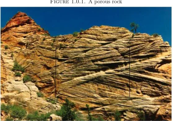
Flow in porous media is another phenomenon that falls in this category. A porous medium is a solid material that is permeated with miniscule pores that allow the transport of a fluid through it like a sponge. An example of a porous medium in nature is a subsurface rock formation as in figure (1.0.1). Flows in porous media with practical significance arise in enhanced oil recovery and contaminant transport in groundwater. During enhanced oil recovery, a substance such as water or carbon dioxide is pumped through a well to the surrounding porous medium that is satu- rated with oil. The water or carbon dioxide displaces the oil into nearby wells from
Figure 1.0.1. A porous rock
which it can be collected. During contaminant transport in ground water a polluting substance contaminates a water reservoir. They can be modeled by the equations of incompressible immiscible two-phase flow
∇λ(S)K(x, y)∇P = 0
v = λ(S)K∇P St+v· ∇f(S) = 0,
where P is the pressure, S is the saturation, which is the volumetric ratio of oil or contaminated water to total liquid, andK is the permeability. Note that the pressure equation is coupled to the saturation equation in a nonlinear fashion.
Experiments performed in laboratories can characterize the permeability and other properties of porous rocks on the micron scale, and well logs provide data on the scale of centimeters. Seismic imaging is used to extrapolate the information between wells.
Both enhanced oil recovery and contaminant transport involve transport over a length scale of kilometers. The large difference between the length scale on which we know the properties of the rock and the scale over which it is transported, the length scale
of the average flow that we are interested in, makes the cost of direct simulation prohibitive. Even if it were feasible, a direct simulation would waste computational resources because it would provide a much more detailed description than is needed to assess whether enough oil would be recovered or the water supply can be used.
There have been a number of efforts to upscale flow in porous media. Among the general categories of upscaling methods are averaging, percolation theory, ho- mogenization, and hybrid approaches. In an averaging method we derive a cascade of equations, with mean flow and higher-order fluctuations, and we obtain a descrip- tion on a coarse level by truncating this cascade to some order. In homogenization we examine a sequence of problems with decreasing pore size but constant pore vol- ume and consider the limiting process to describe the upscaled flow. Averaging and homogenization both assume a more or less homogeneous pore structure. This as- sumption fails in the presence of one connected pore that runs through a large part of the domain, which is referred to as a fast channel, or more generally in the presence of structures with long-range correlation. Such structures will be missed by an up- scaling procedure that uses only local information. Such structures arise naturally in porous media near fault lines and cracks in the rock as in figure (1.0.1). Incorporating them accurately in an upscaled model is crucial because most of the transport occurs through them. Percolation theory is based on the opposite assumption as homog- enization and averaging, that transport occurs only through a network of such fast channels and provides models where the connectivity is important rather than the local description.
Our approach is based on homogenization and averaging, but in a setting that will make up for these shortcomings. We will combine these two approaches with an adaptive coordinate transformation defined by the pressureP and the streamfunction Ψ. The transformation will detect and account for fast channels and resolve the inter- face region between oil and water where the largest changes in the flow profile occur.
We will use homogenization and averaging to treat the rest of the flow regions where the pore structure is indeed more or less homogeneous. Many upscaling methods that have been proposed in the literature are ad hoc. Instead we will try to derive
a rigorous estimate of the upscaling error and provide a solid mathematical founda- tion for our upscaling methodology. We will also test it for benchmark permeability models such as the Tenth SPE Comparative Solution Project [11] and the synthetic channelized fields considered in [10] both for accuracy and computational cost.
The coordinate transformation that we use was inspired by the successes of the time of flight method when applied to the saturation equation. The streamfunction Ψ was first introduced by Muskat [38] in the context of two-phase flows. It was first used by Higgins and Leighton [26] in the context of a numerical method to define streamtubes through which transport occurs. They mapped the transport equation to the streamtubes and used the fact that it becomes one-dimensional to solve it.
Thiele [50] followed the same approach, but accounted for the changes in mobility by periodically recalculating the width of the streamtubes so his method bears some resemblance to ours. Streamline methods were introduced by Shafer [45] who tracked particles through the domain. Pollock [44] used the exact solution of the particle trajectories under the assumption that the velocity field is piecewise linear. Datta Gupta and King [15] introduced a new coordinate along the streamlines, the τ, in which the saturation equation has a particularly simple form: St+f(S)τ = 0. Blunt, Lui, and Thiele extended the streamline method to include diffusion and gravity effects, which lead to the modern streamline methods. Streamline and streamtube methods automatically resolve fast channels by virtue of discretizing the flow in Ψ.
More importantly when we use Ψ the saturation equation becomes one-dimensional.
Complementing our coordinate transformation with the pressureP instead ofτ results in an orthogonal transformation. We also note that in time of flight methods it is difficult to include cappilary pressure effects whereas with our formulation it is straightforward. With P instead of τ the saturation equation retains its multiscale structure so that upscaling is meaningful.
Our homogenization approach is based on Nguytseng’s theory of two-scale con- vergence. Nguytseng [41] proposed using oscillatory test functions φ(x, y,x,y) to define the homogenization limit. Such a limit would be an average over all length scales leaving the fast scales x,y intact. If we try to derive the two-scale limit in a periodic domain we stumble upon the fact that the cell problem v· ∇(x,y)S= 0 has
no unique solution. This equation for the cell problem means that the saturation to lowest order is constant along streamlines. To restrict the degrees of freedom con- tained in a general two-scale expansion, E [19] incorporated this piece of information to the expansion by using a test functionφ(x, y,x,y) with v· ∇(x,y)φ= 0. E arrives at a unique two-scale limit, but the equations by which the two-scale limit is defined don’t offer any insight into its structure. Moreover, there is no clear way to design an efficient numerical method based on them. Westhead [53] incorporates the fact that the saturation to lowest order is constant along the fast streamlines by introducing a projection operator onto the average along the fast streamlines and also obtains a unique two-scale limit. He expands the saturation equation into an average and fluc- tuations and uses the projection operator to close the equation for the fluctuations.
The resulting equations are much more revealing about the structure of the two-scale limit, and a numerical method is proposed.
The approach of Westhead assumes a two-scale structure for the velocity field in the Cartesian variables. We will assume a fast variable in the pressure-streamline frame. The upscaling philosophy in this thesis for upscaling either the pressure or the saturation equation is that the geometry of the flow should be reflected in the coordinate system that we use. Also we will not apply the projection only on the fluctuations as Westhead did but will restrict the test functions as E. The implemen- tation of this idea is the main result of this thesis. The idea to use a flow-based coordinate system in the context of homogenization of the incompressible Euler equa- tions appeared first in McLaughlin, Papanicolaou, Pironneau [40]; however they used a slightly different multiscale expansion than we did and did not arrive at a unique homogenization limit.
On a theoretical level the saturation equation in P,Ψ is one-dimensional which allows us to obtain a convergence rate to the two-scale limit that is independent of the assumptions of periodicity and scale separation. We can also carry out the homogenization farther than the two-scale limit using Tartar’s method. On a practical level the homogenized equations that we arrive at are much simplified compared to those of Westhead. In addition consider how the fast flow channels are upscaled with a Cartesian and a pressure-streamline method. In the Cartesian frame they are thin
and they are grouped together with slow channels resulting in a large upscaling error.
In the pressure-streamline frame they are wider because the transformation focuses the computational points in the fast regions and they are grouped separately from the slow channels. This leads to a more accurate upscaling method. We apply our upscaling philosophy to the pressure equation and complete our upscaling method for the two-phase flow equations.
In the second chapter we describe the physical phenomena that occur during flows in porous media, present their equations, and demonstrate the difficulties that arise in modeling. We select the simplified model of side-to-side incompressible flow with no capillary effects, which retains the essential difficulties in upscaling, the presence of small scales that affect the large scale flow in a significant way. While describing a naive approach to solve numerically the two-phase flow equations we introduce concepts involved in designing a numerical method for the two-phase flows that will be used in later chapters to design an accurate upscaling method. Finally we show a few numerical results and highlight the essential features in the solution such the shock at the interface and the presence of long fingers.
In the third chapter we introduce the coordinate transformation to the frame defined by the pressure and the streamfunction. Our upscaling method that is de- scribed in the next chapters will be based on this coordinate system so we describe its properties in detail. In a pressure-streamline coordinate frame the two-dimensional transport equation is decoupled into a family of one-dimensional equations and the grid is focused in the high flow regions. We show how these two properties can be used together with a moving mesh to design a method that is easy to implement and superior to the method in the Cartesian frame, described in the first chapter. In nu- merical experiments with realistic permeability fields we observe that the numerical method in the pressure-streamline frame converges faster, that the error constant is smaller. This concludes the part where the discretization grids resolve the fine scale of the permeability and leads us to chapters three and four where the discretizations do not resolve the small scales.
In the fourth chapter we upscale the hyperbolic equation of the two-phase flow equations. For that we restrict ourselves to one-phase flow. When we look at the
velocity field in the pressure-streamline coordinates the fast channels are magnified and the variation of the velocity field over the coarse scale is smaller. The flow is more or less uniform in the coarse cells of a coordinate system that follows the flow. We obtain the homogenization of the equation, using two-scale convergence that had been obtained in the Cartesian scheme in the nineties. The two results are different because they are valid under assumptions of two different multiscale structures. Yet we compare them and conclude that the approach in the pressure- srteamline frame leads to simpler equations that are easier to solve. We show weak convergence and rigorously estimate the upscaling error of the two-scale limit without using the assumption of periodicity and scale separation. Then we average out the fast dependence of the two-scale limit across the streamlines using Tartar’s method to obtain a fully homogenized equation. It is not clear how to design an efficient method using that equation, so we use an averaging approach to remove the fast dependence of the two-scale limit across the fast streamlines following Efendiev and Durlofsky [20, 21]. The advantages of the resulting method are demonstrated on realistic permeability fields in terms of accuracy and time of computation.
In the fifth chapter we apply the same upscaling philosophy to the elliptic equa- tion. We use the multiscale finite element method that is based on the homoge- nization theory for elliptic operators. Before we apply the method we transform to the pressure-streamline coordinates to deal with the long-range structures of the permeability field. Our approach has all the advantages of an improved version of the multiscale finite element method, called the modified multiscale finite element method, and also treats fast channels more effectively. This leads to very accurate upscaling as we demonstrate in numerical experiments. Finally we combine the two approaches and present numerical results for the full two-phase flow.
Part 1
Resolved Scheme
In the first part we introduce the equations and the physical phenomena that they describe. We examine the properties of the pressure-streamline frame in terms of adaptivity. We assume that all the quantities are smooth when we discretize them.
That is, if we denote by the length scale on which the quantities fluctuate, then we assume that our grid is such that > h and it resolves all scales.
Chapter 2
The Porous Media Equations in the Cartesian Frame
2.1. Derivation of the Physical Model
We will start by introducing the phenomena that take place in a porous medium and deriving a quantitative description for them. A porous medium is a solid medium that is permeated by miniscule pores that allow the transport of a gas or a fluid. That gas or fluid is often referred to as “phase”. We will restrict ourselves to immiscible flows, flows where the two phases are separated by a distinct boundary and don’t mix. We will also consider phases that do not react with each other. In general, the motion of any fluid is described by the Navier-Stokes equations. For a flow in a small pipe the Reynolds number, which quantifies the relative importance of convection of momentum to viscous diffusion of momentum, is V Lν , where V is the velocity, L is the characteristic length scale, the diameter of the pipe in this case, and ν is the kinematic viscosity. In our case all three quantities are such that the Reynolds number is very small and in this limit the Navier-Stokes equations reduce to the linear Stokes equations.
The pores are on a much smaller length scale than the length scale of the average transport, so there have been early on attempts to derive a physical law on a larger length scale. In 1856, Darcy discovered empirically a law, which now bears his name, and describes the transport of one fluid in a porous medium. Darcy’s law can be
written as
(2.1.1) v =−K
µ(∇Π−ρg∇D),
where v is the velocity of the fluid, K is the permeability of the medium, µ is the viscosity, Π is the pressure,ρis the density of the fluid,gis the constant of gravity, and Dis depth. Darcy’s law essentially states that the velocity of the fluid is proportional to the gradient of pressure. The permeabilityK is an empirical constant that depends only on the geometry of the porous medium and describes how fast the fluid moves through the region for a given pressure gradient. The same law has been recently derived from the Stokes equations using homogenization (for the details we refer the interested reader to [27]). Darcy’s law is complemented by an equation for the conservation of mass of the fluid
(2.1.2) ∇ ·(ρv) +q= ∂(φρ)
∂t ,
whereq denotes sources or sinks in the domain, andφ is the ratio of the pore volume available to the fluid to the total volume, referred to as porosity. Porosity describes how much volume is available to the fluid and does not depend on the geometry of the pores, while permeability describes how the geometry and connectivity of the pores affect the mean flow. We can consider the porosity to be the density of the rock. Passive transport of contaminant through the water of porous medium can be described by (2.1.1), (2.1.2). It is referred to as one-phase flow.
For flows of two different fluids in a porous medium, Muskat [39] first postulated that Darcy’s law holds for each fluid separately
(2.1.3) vw = −Kµww(∇Πw−ρwg∇D) vn = −Kµnn(∇Πn−ρng∇D).
The two different fluids have been denoted with subscriptsn andw for “non-wetting”
and “wetting”. This refers to the fact that the walls of the porous medium show preference in being covered by one of the two fluids. Which fluid covers the walls of the porous medium determines the contact angle of the interface of the two fluids with the wall and the capillary pressure. Usually water is more wetting than oil and
a gas would be the least wetting phase of the three. The difference of the pressures of the two phases is equal to the capillary pressure
(2.1.4) Πn−Πw = Πc.
Darcy’s law for one fluid (2.1.1) is much simpler to work with than for two fluids, as in (2.1.3), because in (2.1.1) the permeability K depends only on the porous medium whereas in (2.1.3) Kw is the permeability of the porous medium combined with the non-wetting phase and obviously depends on the distribution of the non- wetting phase, likewise forKn. We refer toKw, Kn as the relative permeability. Our goal is to derive equations for the flow of two fluids where the influence of the pore structure and the influence of one fluid on the other are separated and their nature is elaborated. Then the resulting equations would be as simple as the equations for one fluid in a certain sense.
Experiments have shown that the relative permeabilities depend only on the ratio of the concentration of the fluids that are involved and are more or less independent of their type of fluids, their velocities and pressures, or the past flow profiles. This means physically that the flow reaches its steady state locally. For a discussion of cases when this assumption fails and the flow is not at equilibrium locally we refer to Barenblatt [3]. To utilize this experimental observation we will introduce the concepts of saturation and phase mobilities.
We will denote bySw(x, y) the ratio of pore volume occupied by the wetting phase to the total pore volume and refer to it as the saturation of the wetting phase, likewise for Sn. By definition we will have
(2.1.5) Sw+Sn= 1.
The phase mobility λw is defined as λw = KµKww, likewise for the non-wetting phase.
We write Darcy’s law in terms of the phase mobilities (2.1.6) vw = −λwK(∇Πw −ρwg∇D)
vn = −λnK(∇Πn−ρng∇D).
In this framework the experimental observation that relative permeability only de- pends on the ratio of the concentrations can be translated as
λw =λw(Sw) and λn =λn(1−Sw).
The conservation of mass (2.1.2) can be written in terms of the saturations and velocities of each phase as
(2.1.7) ∇ ·(ρwvw) +qw = ∂(φρ∂twSw)
∇ ·(ρnvn) +qn = ∂(φρ∂tnSn).
Equations (2.1.7), (2.1.3) are general and can apply to flows with any number of phases. We have included the effects of compressibility of the phases and the porous medium and of capillary pressure.
2.1.1. Pressure Equation. To derive the pressure equation analogous to the pressure equation for one-phase flow we first define an average pressure Π as
Π = Πw+ Πn
2 .
We can write the pressure of the wetting and non-wetting phases in term of the average pressure as
(2.1.8) Πw = Π−Π2c
Πn = Π + Π2c. We combine (2.1.7), (2.1.3) to obtain
(2.1.9) ∇ ·(ρw(−λwK(∇Πw−ρwg∇D))) +qw = ∂(φρ∂twSw)
∇ ·(ρn(−λnK(∇Πn−ρng∇D))) +qn = ∂(φρ∂tnSn).
Quantities φ, ρw, ρn depend on the pressure since the phases and the medium were assumed to be compressible. We define compressibility as the relative change in volume divided by the change in pressure required to achieve it. Mathematically, we
let
Cφ = 1 φ
dφ dΠ Cn = 1
ρn
dρn
dΠn
Cw = 1 ρw
dρw dΠw
.
We make this dependence of the right hand side of (2.1.9) on the pressures explicit by expanding the time derivatives and writing (2.1.9) in terms of the compressibilities
∇ ·(ρw(−λwK(∇Πw−ρwg∇D))) +qw =ρwSwφCφ
∂Π (2.1.10) ∂t
+φSwρwCw
∂Πw
∂t +φρw
∂Sw
∂t
∇ ·(ρn(−λnK(∇Πn−ρng∇D))) +qn =ρnSnφCφ
∂P (2.1.11) ∂t
+φSnρnCn
∂Πn
∂t +φρn
∂Sn
∂t . Now we divide (2.1.10) by ρw and (2.1.11) byρn and add the results to eliminate the time derivatives of Sw, Sn. We use equations (2.1.5), (2.1.8) to obtain an equation for Π
− 1
ρw∇ ·(ρwλwK∇)− 1
ρn∇ ·(ρnλnK∇)
Π +
1
2ρw∇ ·(ρwλwK∇)− 1
2ρn∇ ·(ρnλnK∇)
Πc
+ 1
ρw∇ ·(ρ2wKg∇) + 1
ρn∇ ·(ρ2nKg∇)
D+Q
=φ(Cφ+SwCw+SnCn)∂Π
∂t +φ
2(−SwCw+SnCn)∂Πc
∂t .
We have denoted the sources and sinks by Q. The resulting equation is parabolic in Π or Πc.
We would like to make some simplifications in this equation, while still keeping the terms that describe the essential physics and that are the most difficult to model numerically. In practice the capillary pressure is much smaller than the average pressure so we can neglect it. Furthermore we can treat the gravity term as external
forcing in the same way thatQwill be treated so we will refer to them as∇ ·Gp. The equation becomes
− 1
ρw∇ ·(ρwλwK∇)− 1
ρn∇ ·(ρnλnK∇)
Π+∇·Gp+Q=φ(Cφ+SwCw+SnCn)∂Π
∂t . We regard the quantity Cφ+SwCw +SnCn as the total compressibility. Then the above equation is analogous to the corresponding equation for one-phase flow with a time-independent porosity, which arises from the combination of (2.1.1), (2.1.2)
1
ρ∇ ·(ρλK∇)Π =φC∂Π
∂t .
Our final assumption is that the medium and the phases are incompressible. This assumption is justified in the case of fluids moving through the rock. When a gas is used to displace the oil the effects of compressibility cannot be ignored; however the complications that they create can be treated in a similar way as in the incompressible case. Our final equation for the pressure is
(2.1.12) (−∇ ·(λwK∇)− ∇ ·(λnK∇)) Π +∇ ·Gp+Q= 0.
Based on the analogy with one-phase flow we can define a total velocity v to be (2.1.13) v= (λw+λn)K∇Π +Gp =vn+vw.
In this work we will neglect the gravity and source terms for simplicity.
2.1.2. Saturation Equation. Following the same line of thought we derive an equation for the saturation that involves average quantities rather than quantities specific to a phase. We substitute Darcy’s law for two phases (2.1.3) into (2.1.4) in terms of the gradients to obtain
vn+vw = v
− vn
λnK +ρng∇D+ vn
λnK −ρng∇D = ∇Πc.
We can solve for the velocities of each phase in terms of the average velocity and the capillary pressure. We have
vw = λw
λw+λn
v+ λw
λw +λn
λnK∇Πc+Gs.
We have lumped all the terms involving gravity intoGs. We will make the assumption that the capillary pressure depends only onSw and write the velocity of the wetting phase as
vw =fwv+hw∇Sw +Gs, where
fw = λw
λw+λn
hw = λw
λw+λn
λnKdΠc
dSw
.
With this expression for the velocity the equation for the saturation of the wetting phase can be written as
∇ ·(ρwfwv) +∇ ·(ρwhw∇Sw) +∇ ·(ρwGs) +qw = ∂(φρwSw)
∂t .
In the average pressure equation (2.1.12) the sources Q refer to the points of injection of water and collection of oil. Away from these points (2.1.12) shows that the average velocity v is incompressible. Then we see that the saturation equation is a parabolic equation
v· ∇(ρwfw(Sw)) +∇ ·(ρwhw∇Sw) +∇ ·(ρwGs) +qw = ∂(φρwSw)
∂t
that describes convection by the average velocity v and a nonlinear flux function f(Sw) in the presence of diffusion due to capillary forces and external forcing due to gravity. Mathematically, the significance of the diffusion due to capillary pressure is that it selects a physically relevant weak solution for the nonlinear conservation law.
In practice at the length scales that geological data are available, diffusion due to capillary forces is negligible. Moreover modeling and upscaling become more chal- lenging when the transport is convection dominated rather than diffusion dominated.
We simplify the saturation equation by omitting the forcing terms due to gravity and
the capillary forces that would add unnecessary complications without illustrating better any of the concepts to be presented. We will also assume that the fluids are incompressible. In the case of oil and water this is a valid assumption; moreover the transport of a compressible fluid must be dealt with in a manner that is consis- tent with the incompressible case. Finally we assume that the porosity is constant throughout the medium. With these assumptions the saturation equation reduces to (2.1.14) v· ∇(fw(Sw) = ∂Sw
∂t .
This equation was discovered by Buckley and Leverett [8] and bears their names.
Given Sw we can easily compute Sn by (2.1.5). Equations (2.1.4), (2.1.14) have the desirable property that the influence of the porous medium and the interaction of the two phases have been separated and encoded intoK andfw,λ, a form that is intuitive and can be quantified easily by experimental measurements. The most widely adopted model for λw and λn is
λw(Sw) = Sw2
λn(Sw) = m(1−Sw)2,
where m is the mobility ratio. With these constitutive relations we have λw(Sw) +λw(Sw) =λ(Sw) = Sw2 +m(1−Sw)2
λw
λw+λn
=fw(Sw) = Sw2
Sw2 +m(1−Sw)2. (2.1.15)
One-phase flow can be recovered from the equations of two-phase flow by choosing λ(S) = 1 and a linear flux fw(Sw) = Sw. We note that for two-phase flow the pres- sure depends dynamically on the saturation throughλ whereas in one-phase flow the pressure and saturation equations are decoupled and the pressure is time-independent.
2.1.3. Model Problem. To make the presentation simpler we restrict ourselves to flows in the unit square. There are two types of two-dimensional flows that are widely considered, side-to-side and corner-to-corner. Corner-to-corner flow refers to flow across opposite corners of the unit square and side-to-side refers to flow across opposite faces. If we consider a three-dimensional underground flow from a well
into which water is pumped to a well where oil is collected, corner-to-corner flow corresponds to a horizontal cross-section and side-to-side corresponds to a vertical cross-section. In this work we will mostly consider side-to-side flows for convenience and show how to treat corner-to-corner flows in a similar way. Instead of the physical pressure Π we will substitute for it Π = 1− P and refer to the new variable as pressure P with a slight abuse of terminology. For the rest of this work we will drop the subscripts w.
Then the equations (2.1.12), (2.1.14) of the previous section for pressure P and saturation S in a Cartesian frame are
∇λ(S)K∇P = 0
v = λ(S)K∇P
∇2Ψ = −∇⊥·v St+v· ∇f(S) = 0.
(2.1.16)
The boundary and initial conditions are (2.1.17)
P(x= 0) = 0 ∂yP(y= 0) = 0 Ψ(y= 0) = 0 ∂xΨ(y = 0) = 0 S(x= 0) = 1 P(x= 1) = 1 ∂yP(y= 1) = 0 Ψ(y= 1) =c ∂xΨ(y = 1) = 0 S(t= 0) = 0.
We have denoted by ∇⊥· the operator that maps the velocity vector to the vorticity,
∇⊥·(vx, vy) =−∂yvx+∂xvy.
Ψ is the streamfunction and is defined to be constant on the streamlines. The streamfunction is not part of the standard set of two-phase flow equations, but is important for our approach so we have added it to (2.1.16). The Dirichlet boundary condition on the pressure designates thex= 0 boundary as the inlet, the point where water or contaminant is pumped, and the x = 1 boundary as the outlet, the point where it is collected. The Neumann condition for the pressure imposes that there be no outgoing flow at they = 0 and y= 1 boundaries. The streamfunction is constant on the integral lines of the velocity field; its level sets follow the flow. The constant ccan be chosen arbitrarily. We will chose c=R1
0 udy, so that Ψy =u.
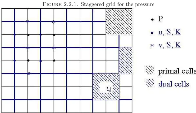
Figure 2.2.1. Staggered grid for the pressure
In a finite volume scheme for the pressure equation, the permeability and the velocity are defined on the edges of the dual cells and the pressure is defined in the
centers of the dual cells.
2.2. Resolved Scheme
Next we will derive a numerical method for the model problem (2.1.16) and in- vestigate numerically the properties of the solutions. On the way we will illustrate some of the issues involved in the design and how they are tackled. This numerical method will serve as a basis for our upscaled scheme that will be developed in part two. We will also introduce some measures to quantify the flow.
2.2.1. Finite Volume Method for the Pressure equation. For the pressure equation we will employ a finite volume (FV) method. Practically speaking a finite volume method arises from a straightforward finite difference discretisation on a stag- gered grid. We partition the domain into rectangular cells that define the primal grid, as in figure 2.2.1. Connecting the centers of the cells we obtain the dual grid.
To derive the finite volume discretisation we start from the integral formulation of the pressure
Z
Ωi,j
∇λ(S)K∇P dA= Z
∂Ωi,j
v·ndS = 0.
This equation holds over all subsets Ωi,j of our domain, in particular over the cells of the primal grid. If we assume that the velocity is piecewise constant over the edgesk of the dual control volumes Ωi,j and the pressure is piecewise linear in Ωi,j we arrive at the following discretisation
X
edgekof Ωi,j
vk·nk = 0 (2.2.1)
Pi+1,j−Pi−1,j = vk·nk
λ(S)K Pi,j+1−Pi,j+1 = vk·nk λ(S)K.
Note that the velocity vi is conservative because it satisfies (2.2.1).
2.2.2. Finite Volume Method for the Saturation Equation. For the time discretisation of the saturation equation in (2.1.16) we use an Implicit Pressure Ex- plicit Saturation Scheme (IMPES). We assume that in the time interval (t0, t0+ ∆tP) the velocity remains constant and is equal to its value at time t0. Physically, this is equivalent to assuming that in the time interval (t0, t0+ ∆tP) we have one-phase flow.
For example a first order IMPES method in time would be given by
∇λ(St)K∇Pt= 0
vt=λ(St)K∇Pt (2.2.2)
St+∆t−St
∆t −vt· ∇f(S) = 0.
The nonlinear coupling of the saturation and the pressure equation occurs through the velocity. If we discretize the two-phase flow equations as in (2.2.2) we will obtain an explicit expression ofS in terms of quantities at time t0, in particular in terms of the velocity. The velocity vt in turn is coupled to the pressure in an implicit fashion since its formula contains the saturationStat time t0. The scheme will be first-order in time, independently of the rest of the discretization because the velocity is assumed to be piecewise constant in time.
For the spatial discretization of (2.2.2), the cells of the finite volume scheme are the cells of the dual grid. The flux (2.1.15) of the Buckley Leverett equation is nonconvex
and could in general require special treatment in the numerical scheme. For a general nonconvex scalar conservation law, Osher [42] discovered a functional relation for the saturation and its flux in terms of the similarity variable xt. Evaluating this relation at
x
t = 0 corresponds to a stationary frame and gives the flux for the Riemann problem, which is what we need in the construction of the numerical scheme. It turns out to be the same as in the case of convex flux. We defer the rest of the details until section 3.3.3.
It is very crucial that the CFL condition is not violated. In some cases if the CFL condition is violated the saturation does not blow up, but instead we obtain a solution that does not satisfy the entropy condition.
2.3. Some Numerical Results
There are three widely used quantities of interest in two-phase flows that quantify numerical error. We will look at the relative error, defined as kexact−computedk
kexactk . TheL1
norm of the saturation can be interpreted as the total amount of transported fluid in the domain and can be used to investigate whether a method is conservative or not.
We can use other Lp norms, but we note here that it is meaningless to consider the maximum norm when the exact solution has a discontinuity as the saturation does.
Quantities related more to practical applications are the breakthrough time, which is the time that water first reaches the collection well, the fractional flow rate (ffr), and the pore volumes injected (pvi). The fractional flow rate is defined as
(2.3.1) ffr(t) =
R1
0 f(S)v·ˆxdy R1
0 v·ˆxdy
and describes the volumetric proportion of oil to total fluid that is collected at the outlet well, the quantity that is of most immediate use to the petroleum engineer. In a coordinate frame p, ψ that satisfiesv·xdy˘ =dψ the fractional flow rate becomes
(2.3.2) ffr(t) =
Z 1 0
f(S)dψ.
The pressure-streamline frame that we will introduce in the next chapter has this property so we will use the second form (2.3.2) in our computations. The fractional flow curve is a plot of the fractional flow rate with time, and its integral is the total
Figure 2.3.1. Shock and rarefaction of the Buckey Leverett equation
0 0.1 0.2 0.3 0.4 0.5 0.6 0.7 0.8 0.9 1
0 0.1 0.2 0.3 0.4 0.5 0.6 0.7 0.8 0.9 1
0 0.1 0.2 0.3 0.4 0.5 0.6 0.7 0.8 0.9 1
0 0.1 0.2 0.3 0.4 0.5 0.6 0.7 0.8 0.9 1
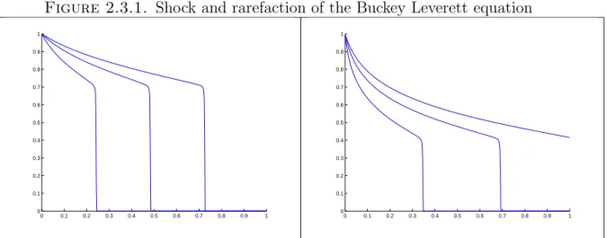
Saturation profiles along a streamline for a nonlinear flux with m= 1 (left) and m= 5 (right) at t= 0.2,0.4,0.6.
amount of oil produced at the outlet until a certain time. Instead of time, fractional flow curves are often reported as functions of pore volumes injected, defined for unit porosity as
pvi= 1 kΩk
Z t 0
Z 1 0
v·xdy,ˆ
where Ω is the area of the domain. Pvi is the time that is required to inject an amount of fluid equal to the capacity of the oil reservoir, essentially it is a rescaling of time.
We discuss briefly some characteristics of two-phase flows. We show a plot of the saturation profile along a streamline at different times in figure 2.3.1. The saturation develops a shock whose strength diminishes as time passes. The shock is followed by a rarefaction wave. As the mobility increases, the shock strength decreases. In figure 2.3.2 we show a saturation profile in two dimensions computed in Cartesian coordinates with the method described in this chapter. In flows in two and three dimensions when the velocity varies rapidly across the flow lines, the saturation profile develops fingers along the fast channels of the flow. We are interested in resolving the fast channels and upscaling over adaptively selected regions where the flow is more or less uniform. Note that the presence of numerical diffusion smears the shock out. The grid that was used was 60×60, which explains why the resulting saturation profile is smeared. This effect will be much reduced when we use an adaptive coordinate frame, and we will be able to see the fingers more clearly.
Figure 2.3.2. Fingering in two phase flows
0.1 0.2 0.3 0.4 0.5 0.6 0.7 0.8 0.9
When the permeability field varies strongly across the flow, the saturation profile develops fingers.
Chapter 3
An Adaptive Framework for
Solving the Porous Media Equation
3.1. Context of the Present Work
The most successful attempt to design an adaptive numerical method for the transport equation in oil reservoir simulation and ground water flow is the time of flight method. It was slowly developed by many researchers and expanded to apply to the many physical phenomena that arise in two-phase flows. A detailed review of these efforts can be found in [4]. The central idea is to track the streamlines of the flow and solve a one-dimensional transport equation along them
St+|v| d
dsf(S) = 0,
where s denotes arc length. Datta-Gupta and King [15] introduced time of flight, which is central to modern streamline methods. It is defined by
τ = Z s
0
dζ
|v(ζ)|.
If we change variables from s to τ we arrive at an equation whose solution is easy to compute because it does not contain the velocity field
St+ d
dτf(S) = 0.
Time of flight satisfies the ikonal equation on the plane 1 =|v|dτ
ds =|v|∇τ· v
|v| =⇒ v· ∇τ = 1.
From this equation it is clear τ is a well-defined function in the plane. (τ, ψ) is not an orthogonal system of coordinates. To see this we can consider the case of shear flow that arises when K = 1−y. Then the velocity field is v = (1−y,0) and the streamlines simply y=const. Time of flight is given byτ = |1−y|x so its level sets are not perpendicular to those of the streamfunction. The pressure is given byP =xand (p, ψ) is an orthogonal system. This fact holds generally as we will see. Our approach, which will be described in the next section, is based on the coordinate framep, ψ and has all the advantages in terms of adaptivity as the streamline method. In addition it is easier and more meaningful to try to upscale in p, ψ coordinates compared to (τ, ψ) as will become apparent in part two.
3.2. The Pressure-Streamline Frame
3.2.1. Coordinate Transformation. We will make a change of variables from (x, y) to (p, ψ) as defined above. The elements of the Jacobian matrix of the trans- formation and its inverse are computed below. They relate the differential inX, Y to the differential inP,Ψ
dX dY
=
XP XΨ
YP YΨ
dP dΨ
=J−1
dP dΨ
dP dΨ
=
Px Py
Ψx Ψy
dX dY
=J
dP dΨ
. Solving the second equation for dX, dY we get
dX dY
= 1 PxΨy−PyΨx
Ψy −Py
−Ψx Px
dP dΨ
.
Comparing the two equations fordX, dY we find the elements of the Jacobian matrix and its inverse
(3.2.1)
Px = λKu Py = λKv Ψx = −v Ψy = u
XP = kvuk2λK XΨ = k−vvk2
YP = kvvk2λK YΨ = kvuk2
J = kλKvk2 J−1 =kvk−2λK.
This is a time-dependent coordinate transformation so the saturation equation be- comes
St−XtSx−YtSy+v· ∇f(S) = 0.
The second and third terms are due to the motion of the coordinatesp(t), ψ(t). Using the chain rule on the saturation we find
SP
SΨ
=
XP YP
XΨ YΨ
Sx
Sy
.
Solving this equation for Sx, Sy we can write the saturation equation in terms of the pressure and streamfunction variables
St− Xt
J−1(YΨSP −YPSΨ)− Yt
J−1(−XψSP +XPSΨ) + kvk2
λK f(S)P = 0 St− kvk2XtYΨ−YtXψ
λK SP − kvk2YtXP −XtYP
λK SΨ+ kvk2
λK f(S)P = 0.
Note that in this formulation the flux term is one-dimensional. The advantages of the pressure-streamline frame in terms of simplicity and adaptivity are based on this fact. We can substitute the velocity in the last equation. Then the full equations in the pressure-streamline frame are
(3.2.2)
∇λ(S)K∇P = 0
v = λ(S)K∇P
∇2Ψ = −∇⊥·v
St− Xtu+YλKtvSP −(Ytu−Xtv)SΨ+ kλKvk2f(S)P = 0.
3.2.2. Entropy Solutions. In this section we demonstrate that the entropy so- lutions of the two-phase flow equations (2.1.16), (3.2.2) coincide. This is in general not obvious because the equation in the pressure-streamline frame is in nonconservative form. In our particular case the analysis follows easily from the fact that there exists a frame, namely the Cartesian frame, in which the equation is in conservation form.
The first obstacle is that there is no proof of existence and uniqueness of solutions to the coupled two-phase flow equations. There is only a proof of existence of a solution when capillary forces, a diffusion term, are included in the equations [1]. The proof is made more complicated by the fact that the diffusion term is degenerate. When
λ(S) = const the pressure equation is decoupled from the saturation and then we have a unique solution.
For the following we will assume one-phase flow. We will interpret the satura- tion equation in the sense of distributions, so we first derive that formulation for completeness. In the Cartesian frame the weak form of the saturation equation is
Z
R2×R+
(Sφt+f(S)v· ∇φ)dxdydt+
(3.2.3)
+ Z
R2
S(x, y, t= 0)φ(x, y, t= 0)dxdy = 0,∀φ(x, y, t)∈ J.
We change coordinates to arrive at the weak formulation in the pressure-streamline frame
Z
R2×R+
Sφt,fix x+
J−1dpdψdt+
(3.2.4)
+ Z
R2
S(p, ψ, t= 0)φ(p, ψ, t= 0)J−1dpdψ= 0,∀φ(p, ψ, t)∈C∞. The JacobianJ−1 of the transformation was defined in (3.2.1). We have denoted with φt,fix x the derivative with respect to time, keeping x, y fixed. It is well known that when the flux function is nonlinear a hyperbolic equation can have many weak solutions. Motivated by the physical principle that entropy in nature cannot decrease when time increases we define admissible solutions to be the weak solutions that satisfy that property. To determine the correct entropy equation for our equations we start from the weak form of the entropy equation in the Cartesian frame. Let η(µ),q(µ) be an entropy-entropy flux pair. The following entropy condition must be satisfied for every convex entropy for the solution to be unique [13, 34]
Z
R2×R+
(η(S)φt+q(S)v· ∇φ)dxdydt+
(3.2.5)
+ Z
R2
η(S(x, y, t= 0))φ(x, y, t= 0)dxdy≤0,∀nonnegative φ∈ J.
Changing variables we arrive at the correct entropy condition in the pressure-streamline frame
Z
R2×R+
η(S)φt,fix x +q(S)|v|2 λKφp
J−1dpdψdt+
+ Z
R2
η(S(p, ψ, t= 0))φ(p, ψ, t= 0)J−1dpdψ ≥0,∀ nonnegativeφ(p, ψ, t)∈ J or
Z
R2×R+
J−1η(S)φt,fix x+
dpdψdt+
(3.2.6)
+ Z
R2
η(S(p, ψ, t= 0))φ(p, ψ, t= 0)J−1dpdψ≥0,∀nonnegative φ(p, ψ, t)∈ J. The strong form of the entropy condition is
J−1η(S)
t−Xtu+Ytv
λK J−1η(S)
p−(Ytu−Xtv) J−1η(S)
ψ+q(S)p ≤0.
(3.2.7)
The first three terms are the Lagrangian derivative of J−1η(S) in the moving frame p(x, y, t), ψ(x, y, t).
The choice of the space J is not important for one-phase flow but for two-phase flow we must select it to be H1, as we will see in the proof of the following theorem.
Theorem3.2.1.Assume that the system of two-phase flow equations in the Carte- sian frame (2.1.16) together with the entropy condition (3.2.5) interpreted in the sense of distributions φ ∈ H1 has a unique solution. Furthermore assume that the trans- formation x, y → p, ψ is nonsingular in the sense that the elements of the Jacobian matrix and its inverse are bounded. Then that solution coincides with the solution of the two-phase flow equations in the pressure-streamline frame (3.2.2) together with the entropy condition (3.2.7).
Proof. To show that φ(x, y) ∈ H1 ⇔ φ(p, ψ) ∈ H1 we change variables in the definition of the H1 norm and use the fact that the elements of the Jacobian matrix and its inverse are bounded. The transformation x, y → p, ψ is a bijection from H1 toH1 soS satisfies the weak pressure-streamline saturation equation (3.2.4) and