I also take this opportunity to thank all the faculties of the Department of Civil Engineering, IIT Guwahati for their continuous support and encouragement throughout the course of this research work. The validity of the developed analytical solutions is checked by drawing parallel numerical models for some flow situations and then comparing the analytical predictions with the corresponding numerical models.
INTRODUCTION
Objectives
HYDRAULICS OF A POWER HOLE IN A HOMOGENEOUS AND ANISOTROPE UNLIMITED AQUIFER OF A FINITE HORIZONTAL AND VERTICAL EXTENT. In this chapter, the hydraulics of a borehole in a homogeneous and anisotropic phreatic aquifer with finite horizontal and vertical dimensions is studied, both for situations where the hole fully penetrates the aquifer and is located above an impermeable layer and when the hole is partially in the aquifer penetrates and there An impermeable layer exists at a finite distance from the bottom of the hole.
Introduction and Review of Related Work
A particular configuration of the auger hole (recovery test) considered by Dagan (1978) coincides with the auger hole problem of Kirkham (1958) and Boast and Kirkham (1971) and as such it is expected that Dagan's solution to such a situation for an auger hole too. According to Van Beers (1958), the auger hole method measures the average saturated hydraulic conductivity of a soil column extending 30 to 50 cm radially from the center of the hole and a few decimeters below the bottom of the hole.
Objectives
The Neumann limit underestimates the flow in the pin holes, while the Dirichlet limit overestimates it. Since flow in a stressed cross-hole occurs from both the upper water table and the lateral boundaries, a solution to the problem obtained by imposing a Neumann condition on the outer boundary may be significantly different from that developed by taking consider a Dirichlet condition at the outer boundary, especially for flow situations where the anisotropy ratio of the experimental aquifers is high.
A General Solution to the Steady State Continuity Equation of Flow into an Auger Hole in a Homogeneous and Anisotropic soil Medium
It should be noted that in Eq. 2.10), the property is used that the sum of the solutions of a differential equation is also its solution. 2.5) and observing that a constant is also a solution of Eq. 2.1), a general solution, therefore, of the steady-state continuity equation in cylindrical coordinates can be expressed as [see also Eq. 2.12) forms the basis of the analytical solutions that we propose to obtain for the flow problems considered for study in this chapter.
Mathematical Formulation and Solution
- Case 1: Theory of seepage into a fully penetrating auger hole in an unconfined aquifer of finite domain
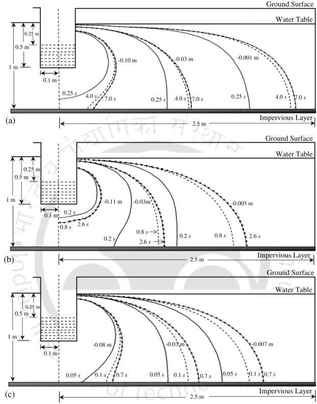
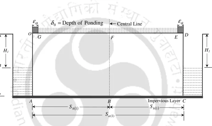
- Case 2: Theory of seepage into an auger hole underlain by an impervious layer in an unconfined aquifer of finite horizontal and vertical extents
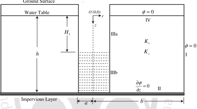
Geometry of the flow system in a wormhole resting on an impermeable layer in an unconfined aquifer with limited horizontal and vertical extents. Again, in light of Eq. Geometry of the flow system in a wormhole underlain by an impermeable layer in an unconfined aquifer with limited horizontal and vertical extents.
Verification of the Proposed Models and Discussion
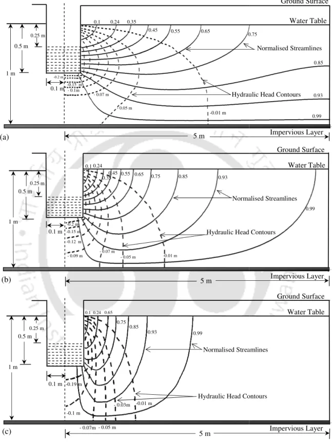
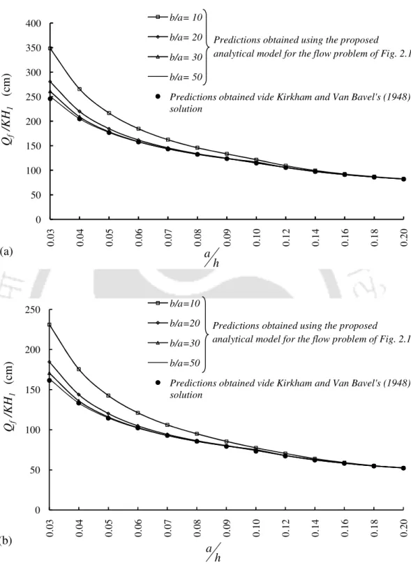
Comparison of Qf KH1 and a h profiles as obtained from the proposed solution to the flow problem of Fig. Comparison of the normalized streamlines as obtained from the proposed solution to the flow problem of Fig.
Field Applications
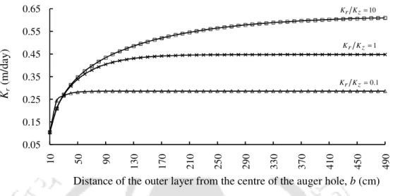
The distance of the outer layer from the center of the drill hole, b (cm) Kr (m/day) Kz (m/day). The distance of the outer layer from the center of the drill hole, b (cm) Kr (m/day). The distance of the outer layer from the center of the auger well, b (cm) Kr=Kz= K(m/day).
Variation of hydraulic conductivity with the distance from the outer layer for the flow situation of Example 3.
Conclusions
The validity of the developed solutions for both the fully and partially penetrating auger problems was checked by first reducing these solutions from an aquifer of finite horizontal distribution to that of an infinite one by using a high value of the distance from the outer layer in these solutions, and then compare the analytical results obtained from them for a few sinkhole situations with identical results obtained from the analytical works of others. The proposed analytical models can be used to convert the experimental data obtained from an auger hole test in a phreatic aquifer to the directional conductivity of the tested aquifer and can also be used to estimate the horizontal extent of the disturbed zone resulting from the test arise, to estimate. It should be noted that this measure of horizontal extent of the disturbed zone associated with the test is important as it provides information about the radial extent of the soil space over which the directional conductivity of the soil was actually measured in the test.
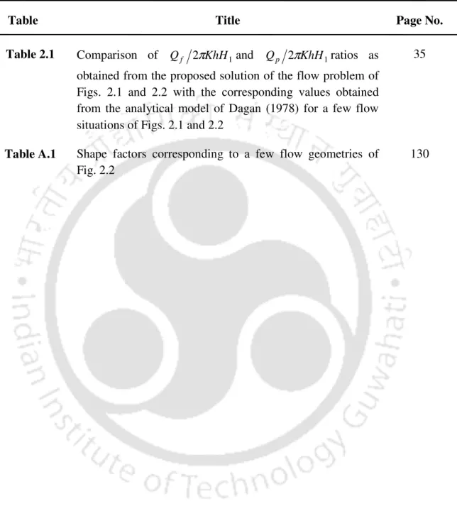
It is hoped that the analytical models proposed here, along with these tabulated form factors, will be useful in estimating the directional conductivities of an unconfined aquifer as well as in constructing a borehole test domain of influence using data obtained from a standard borehole test performed on an aquifer.
List of Notations
The solution to the ditch drainage problem is first obtained by considering the water levels in the adjacent ditches as equal and the dam depth as uniform, it is then solved by assuming that the water levels of the adjacent ditches are so unequal and the dam. depth as uniform and finally a general solution to the problem is reached by assuming that the water levels in the adjoining ditches are so unequal and taking the weir field over the surface of the ground as a variable one, instead of the uniform pond depth assumption made while solutions were derived for the earlier two variants of the problem. The accuracy of the developed models is checked in several cases by comparing them with other simplified models. The effect of depth and spacing of ditch drains, directional conductivity and specific storage of soil, water levels in the adjacent ditches, nature of dam field distribution on the surface of the soil, on drain discharge is also studied.
It is also shown with several examples how the distribution of flow and surface discharge can be modulated in a ponded soil profile by adjusting the water table heights between adjacent drainages and/or by changing the distribution of the pond area over the soil surface.
Introduction and Review of Related Work
This solution can withstand both zero depth and uniform ponding depth on the soil surface. The solution assumes that the width of the ditch is negligible and that there is no depth of the pond on the ground surface. Their solution can take into account the finite width and partial penetration of drainage ditches, soil anisotropy, and both zero and uniform ponding depth on the soil surface.
It has been observed that this is true both for the cases where the surface of the ground is subjected to negligible depth and for uniform depth of puddles.
Objectives
Rao and Leeds-Harrison (1991) reported that desalination away from the drains is greatly improved if the partial excavation of the soil surface is carried out in stages and in a judicious manner. Youngs and Leeds-Harrison (2000) presented a conformal mapping solution to the constant, partially overdrained pipe drainage problem for the situation where the soil profile is subject to an impermeable barrier. From their study, they observed that better uniformity in leaching with less water can be achieved by adopting a progressive leaching procedure compared to the traditional method of completely flooding the soil at once.
In fact, even for the steady state case, there appears to be no analytical model that can account for a variable dam field at the surface of the soil.
A General Solution of the Two-Dimensional Continuity Equation of Transient Groundwater Flow in a Homogeneous and Anisotropic Soil
Since adding solutions of a differential equation will also result in another solution of the differential equation, a solution of Eq. where Amn are all constants, m and n are summation indices, and M and N are any positive integer. We employ a similar procedure to obtain a solution of Eq. 3.8), after some rearrangement of the terms of the resulting equation, we get Recall again that the sum of solutions of a differential equation is also its solution, a solution of Eq. 3.8) can thus be represented using Eq. where Bp and Cq are arbitrary constants, pandq are summation indices, and P and Q are arbitrary positive integers.
As mentioned earlier, since the sum of the solutions of a differential equation is also its solution, the first term of Eq. 3.25) will also yield another solution of Eq.
Mathematical Formulation and Solution
- Case 1: An analytical model for predicting flow into an array of equally spaced ditch drains with equal water level heights in between adjacent drains
- Case 2: An analytical model for predicting flow into an array of equally spaced ditch drains with unequal water level heights in between adjacent drains
- Case 3: An analytical model for predicting flow into an array of equally spaced ditch drains with unequal water level heights in between adjacent drains
- Comparison with a few available steady state solutions
- Comparison with MODFLOW
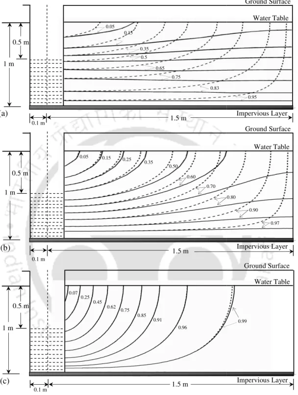
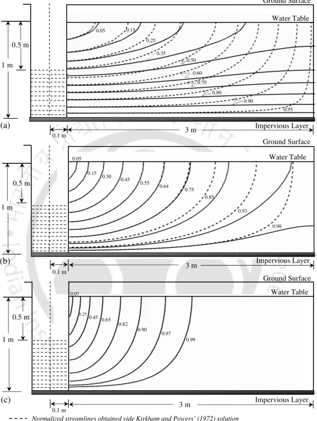
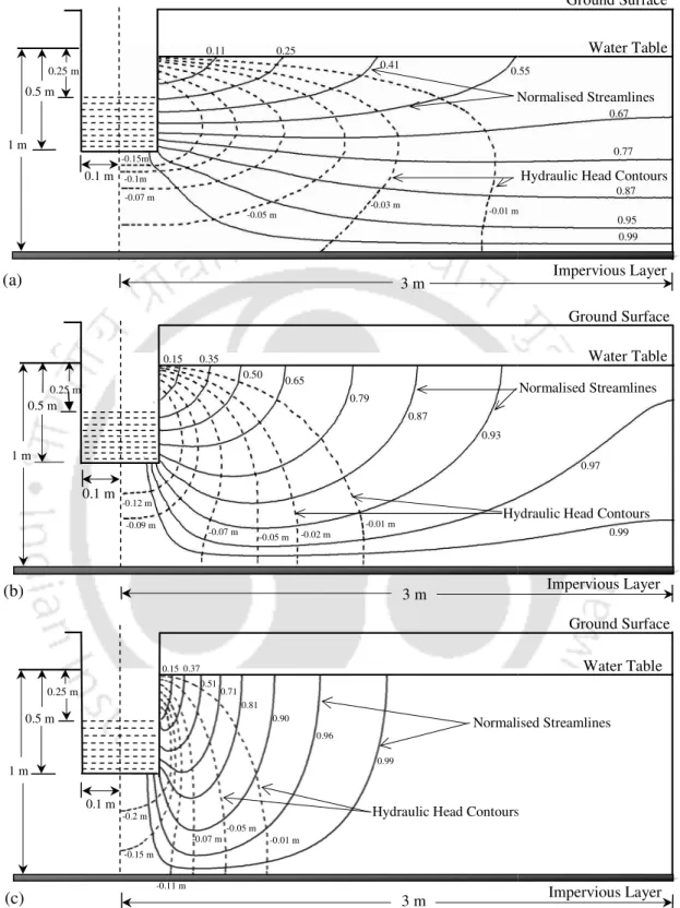
Now the total discharge per unit length of the trenches, Qtop(t) coming from the ground surface, is obtained as. Variation of Qtop(. proposed solution to the flow problem in Fig. 3.3 runs empty) when the other. Comparison of lines of equal hydraulic head and normalized streamlines as obtained from the proposed stationary solution of the flow problem in Fig.
Comparison of equal hydraulic head lines and normalized streamlines as obtained from the proposed steady state solution of the flow problem of Fig. Comparison of hydraulic head contours as obtained from the proposed solution to the flow problem of Fig. The volume of water that has penetrated through the soil surface for the flow situation of Fig.
List of Notations
V volume of water passing per unit length of the trenches through the surface GE of Fig. Q steady state discharge per unit length of the ditches through the surface GE of Fig. S distance of the ith (1≤i≤N0 −1) inner bundle from the origin O in the real plane for the flow problem of Fig.
Furthermore, generalized analytical solutions to the transient ditch drainage problem were also obtained for cases where the flow field over the surface of the lake field is subject to uniform as well as variable depth of lake formation.
Hydraulics of an Auger Hole in an Unconfined Aquifer of Finite Horizontal and Vertical Extents
The proposed analytical models can be used directly to translate the data obtained from a single auger hole test in an unconfined aquifer to the directional conductivity of the aquifer, provided the anisotropy ratio of the aquifer is known in advance. In the event that the anisotropy ratio of the aquifer is not known a priori, an iterative procedure using experimental data obtained from two auger hole tests of different geometries can be employed to estimate both the anisotropy ratio as well as the directional conductivity of the aquifer . The study shows that the domain of influence of an auger hole test in a phreatic aquifer of finite vertical extent and bounded below by an impermeable layer does not extend to an infinitely large distance in the horizontal plane, as was generally assumed in the derivation of the existing auger hole seepage theories (Kirkham and Van Bavel, 1948; Boast and Kirkham, 1971; Dagan, recovery test, 1978; Barua and Tiwari, 1995), but can still be of several meters in the horizontal range, especially if the test is guided in an aquifer with a high anisotropy ratio (ratio of horizontal to vertical hydraulic conductivity of soil).
It is also concluded from the study that the thickness of an unconfined aquifer, the rate of partial infiltration and the water level in a borehole play an important role in determining the flow in the borehole and therefore adequate efforts should be made to including these variables in the mathematical analysis of the problem.
Transient Hydraulics of Flow into Fully Penetrating Ditch Drains Receiving Water from a Ponded Field
Hydrodynamics of the catchment zone of a partially penetrating well in a confined aquifer.” Water resource. Snail Tests in Unconfined Formations: An Assessment of the Bouwer and Rice Technique.” Groundwater. The Auger-Hole Method: A Field Measurement of the Hydraulic Conductivity of Soils Below the Water Table." International Institute for Soil Reclamation and Improvement, Bull.
The snail-hole method; a field measurement of soil hydraulic conductivity below the water table.” 6th ed.