This is to certify that the thesis entitled "Dynamic Stability Improvement of Power System with Fuzzy Logic Based Power System Stabilizer" by Mr. Panda, Professor, Department of Electrical Engineering for his constant motivation, support, expert guidance, constant supervision and constructive suggestion for the submission of my progress report of thesis work "Dynamic stability improvement of power system using fuzzy logic based power system stabilizer". To overcome the disadvantage of conventional power system stabilizer (CPSS), many techniques such as fuzzy logic, genetic algorithm, neural network, etc.
The fuzzy logic based power system stabilizer model is evaluated on a single machine infinite bus power system, and then the performance of Conventional power system stabilizer (CPSS) and Fuzzy logic based power system stabilizer (FLPSS) are compared. Results presented in the thesis demonstrate that the fuzzy logic based power system stabilizer design provides better performance than the Conventional Power System Stabilizer. RFLPSS Robust Fuzzy Logic Power System Stabilizer RNNC Recurrent Neural Network Controller SMIB Single Machine Infinite Bus.
INTRODUCTION
Lin [32] proposed a fuzzy logic power system stabilizer which can shorten the tuning process of fuzzy rules and membership functions. Jain [21] have described the performance of the infinite bus system of a machine with fuzzy power system stabilizer. Gunjan [20] have discussed a study of fuzzy logic power system stabilizer (PSS) for increasing the stability of a multi-machine power system.
Chun-Jung Chen [11] presented an adaptive power system stabilizer (PSS) consisting of a recurrent neural network controller (RNNC) and a compensator to dampen the power system oscillations. To overcome the disadvantages of the conventional power system stabilizer (CPSS), numerous techniques have been proposed in the literature. Presents a frequency response method for the design of a conventional power system stabilizer (CPSS) in the frequency domain.
MODELLING OF POWER SYSTEM
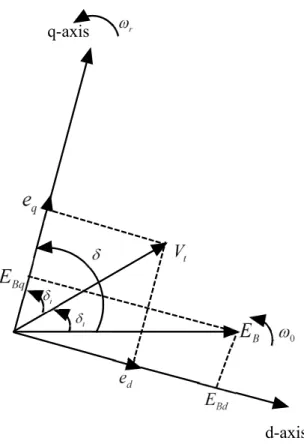
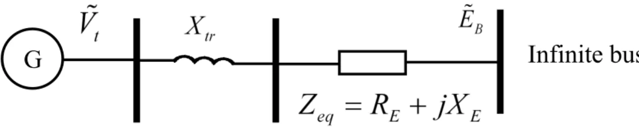
Next, the details of the model will be increased to account for the effects of field circuit dynamics and the excitation system. The classical model representation of the generator [30] and without considering all resistances, the system representation is shown in Figure 2.3. In Figure 2.3, ˜E0 is the voltage for Xd0, which is the transient reactance of the direct axis of the generator.
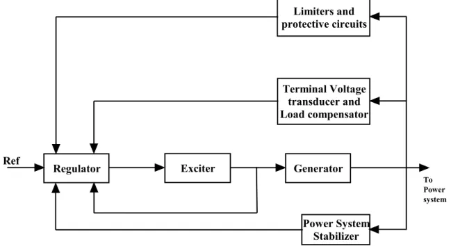
As in the case of the classical generator model, they are linearized equations of motion. The main purpose of the excitation system is to control the field current of the synchronous machine. The field current is controlled to regulate the terminal voltage of the machine.
Below is a brief introduction of the various subsystems identified in Figure 2.6 above. Exciter: Provides dc power to the synchronous field winding of the machine, constituting the power angle of the excitation system. To obtain the state-space representation of the system, the state vector must be redefined.
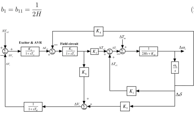
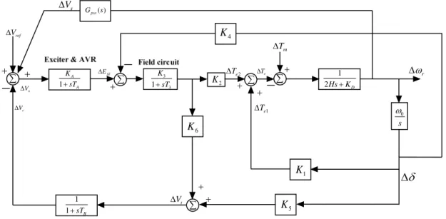
If K5 is positive, the effect of the AVR is to introduce a negative synchronization torque and a positive damping torque component. A number of factors can affect the damping coefficient of a synchronous generator; including the design of the generator, the strength of the machine's connection to the electricity grid and the setting of the excitation system. A number of factors can affect the damping coefficient of a synchronous generator, including the design of the generator, the strength of the machine's connection to the electrical grid, and the setting of the excitation system.
Generator power factor (leading power factor operation is more problematic than lagging power factor operation). The theoretical basis for PSS can be illustrated using the block diagram shown in Figure 2.12. This is an extension of the block diagram shown in Figure 2.8 and includes the effects of PSS.
CONVENTIONAL POWER SYSTEM STABILIZERS
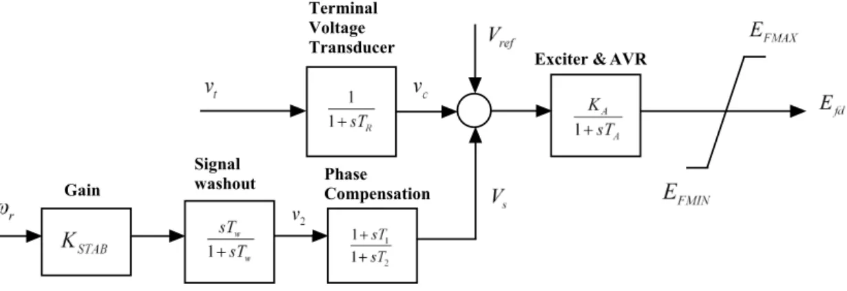
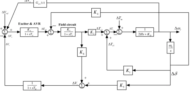
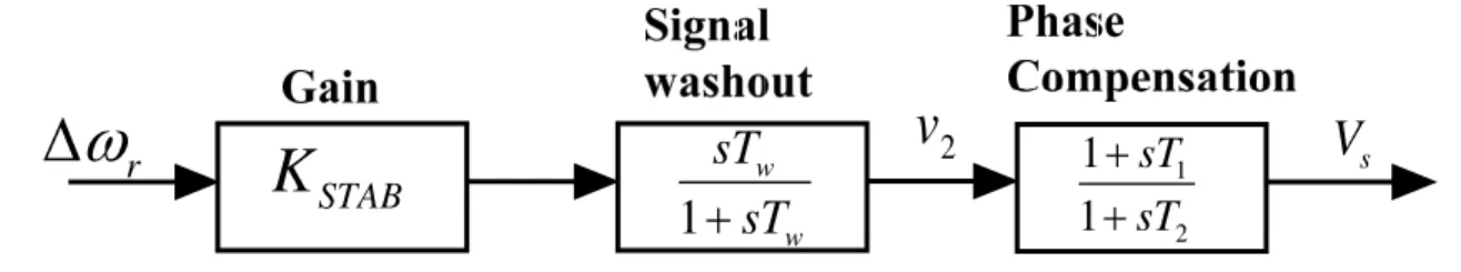
In Figure 3.1, the phase compensation block provides the appropriate phase shift characteristics to compensate for the phase lag between the exciter input and the generator electrical torque. The phase offset can be a single first-order block as shown in Figure 3.1 or have two or more first-order blocks or second-order blocks with complex roots. By adding a PSS to the block diagram shown in figure 2.8, the block diagram of the power system with PSS as shown in figure 3.3 is obtained.
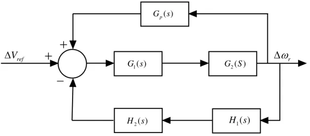
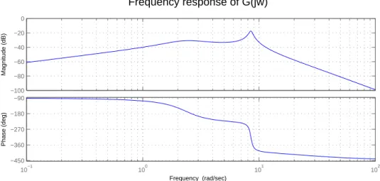
The block diagram in Figure 3.3 can be reduced to the block diagram shown in Figure 3.4, where. The block diagram in Figure 3.4 can be simplified to the block diagram shown in Figure 3.5. Bode plot of the plant without PSS (G(s)) for this operating mode is shown in Figure 3.6.
In the case of cascade (series) compensation, the effect of the controller on the closed-loop transfer function is directly determined. However, the effect of the feedback compensator on the closed-loop transfer function of the system is not easily determined. This means that the overall transfer function of the system will be approximately equal to −G 1.
This means that the output of Gp(s) will have an opposite phase to the input to G(s), causing a negative feedback (note positive signs on the comparator inputs in Figure 3.4). From figure 3.9 it shows that the sharp resonance which was observed in figure 3.6 is smoothed with a smaller magnitude and it occurs at a smaller frequency. Since the design is based on a block diagram of the system derived for a specific op-.
If the operating point of the system changes, the performance of the CPSS will deteriorate.
DESIGN OF FUZZY LOGIC BASED PSS
The importance of fuzzy logic stems from the fact that most human reasoning methods, and common sense reasoning in particular, are approximate in nature. In doing so, the fuzzy logic approach enables the designer to efficiently handle highly complex closed-loop control problems. If the value of the membership function is bounded to 0 or 1, A reduces to a classical set.
The fuzzy logic controller consists of 4 principle components: fuzzification interface, knowledge base, decision-making logic and defuzzification interface. If the output of the defuzzifier is a control action for a process, then the system is a non-fuzzy logic decision system. Step 2: Application of fuzzy operator (AND, OR, NOT) in the IF (preceding) part of the rule.
The output of the fuzzy logic controller is then multiplied by a gain 0K00 to give the appropriate control signal 0U0. The two inputs are the change in angular velocity and the rate of change of angular velocity while the output of the fuzzy logic controller is a voltage signal. The design begins with the assignment of inputs/outputs to the mapped variables of the fuzzy logic controller (FLC).
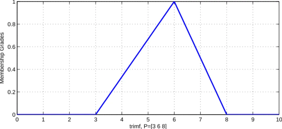
These variables convert the numerical values of the fuzzy controller input into fuzzy quantities. Here, seven linguistic variables are used to describe each of the input and output variables. The procedure for calculating the clear output of a fuzzy logic controller (FLC) for some values of the input variables is based on the following three steps.
In fuzzy logic control, the most used method to derive the rule output is Mamdani method.
RESULTS AND DISCUSSION
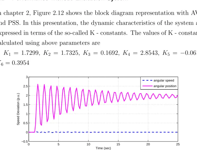
From the above reaction shown in Figure 5.2, it shows that it takes a very long time ie. The time response of the angular speed and angular position with excitation system is shown in Figure 5.3 and Figure 5.4 for positive and negative value of K5 constant. From the Figure 5.5 and Figure 5.6 it shows that the system is stable for both positive and negative value of K5 constant.
The variation of the angular position with PSS based on fuzzy logic for the negative and positive value of the constant K5 is shown in Figure 5.7 and Figure 5.8, respectively. The change of angular velocity with PSS based on fuzzy logic for the negative and positive value of the constant K5 is presented in Figure 5.9 and Figure 5.10. As shown in Figure 5.11 and Figure 5.12, the oscillations are more pronounced in the case of inputs and outputs.
As shown in Figure 5.13 and Figure 5.14, unstable behavior results if the trapezoidal membership function is used with a negative value of the K5 constant. From Figure 5.20 and Figure 5.22 it can be seen that the characteristic of slow response or response over damping has resulted and the settling time remains largely unchanged for the positive value of the constant K5. From Figure 5.21 and Figure 5.22 it shows that the oscillations in angular velocity decrease much faster with fuzzy logic based PSS (FLPSS) than with conventional PSS (CPSS) for both cases i.e.
CONCLUSION AND SUGGESTIONS FOR FUTURE WORK
Lubosny, “Improving power system stability using fuzzy logic-based supervisory power system stabilizer,” inPower and Energy Conference, 2008. Kalra, “Experimental studies using a generalized neuron-based power system stabilizer,” Power Systems, IEEE Transactions on, vol. Yuan-Yih, “Design of a self-tuning pid power system stabilizer for multi-machine power systems,” Power Systems, IEEE Transactions on, vol.
Murdoch, “Power system Stabilisers as undergraduate Control Design Projects”, Power Systems, IEEE Transactions on, vol. Gunjan, “Fuzzy Logic Based Robuste Power System Stabilisator voor multi-machine Power System”, inIndustrial Technology, 2006. 23] ——, “Power System Stabilisers Design for onderling verbonden energiesystemen”, Power Systems, IEEE Transactions On, vol.
Lin, "Systematic approach for the design of a fuzzy power system stabiliser," i Power System Technology, 2004. Pierre, "A fuzzy logic-based adaptive power system stabilizer for multi-machine systems," inPower Engineering Society Summer Meeting, 2000. Malik, "Simplified fuzzy logic controller and its application as a power system stabilizer," i Intelligent System Applications to Power Systems, 2009.
Amiri, “An adaptive fuzzy sliding mode control for power system stabilizer,” in Industrial Electronics Society, 2003. Taher, S.A.; Shemshadi, “Design of a robust fuzzy logic power system stabilizer”, World Academy of Science, Engineering and Technology, No. Ghazi, “Design of augmented fuzzy logic power system stabilizers to improve the stability of power systems”, Energy Conversion, IEEE Transactions on , full.
Li, “Pole-placement power system stabilizers design of an unstable nine-machine system,” Power Systems, IEEE Transactions on, vol.
LIST OF PUBLICATIONS
AUTHOR’S BIOGRAPHY