In order to further improve the detection efficiency, a slow-light π-FBG-based QDSN is proposed. 92 Figure 4.11: (a) Transmission and (b) strain sensitivity spectra of the proposed π-FBG for slow light in a five-level quasi-distributed sensor network.
List of Table
List of Acronyms
SBS Stimulated Brillouin Scattering SDM Space Division Multiplication SHM Structural Health Monitoring SLSR Side Lobe Suppression Ratio. SRI Ambient Refractive Index SRS Stimulated Raman Scattering TDM Time Division Multiplication TMM Transfer Matrix Method.
Introduction and Literature Review
Introduction
Therefore, for the safe and efficient use of structures, regular inspection and maintenance is needed. One of the possible ways to overcome these limitations is to equip the system that utilizes light wave frequencies of the electromagnetic spectrum.
Optical Fiber Sensors (OFSs)
In the following sections, a brief discussion on fiber optic sensors and their topologies is presented. Enormous efforts have been made to nullify the sensitivity of optical fiber to these external parameters.
OFS Topologies for Sensing Applications
Single Point Sensor
Intensity/Wavelength modulation-based OFS
The change in Bragg wavelength due to longitudinal strain, ε, is given by,. where pe is the coefficient of photoelasticity of the fiber and can be given as where p11 and p12 are the components of the strain-optical tensor and υ is Poisson's ratio. Tracking the Bragg wavelength shift of an FBG under an ultrasonic strain wave is usually not possible with an optical spectrum analyzer (OSA) due to its limitation in terms of sensitivity/resolution and demodulation speed.
Interferometer based OFS
Demodulation techniques to be used in this case depend on the light source (broadband source/laser/Erbium-doped fiber laser/modulated laser) used in a detection system [45]. A moderate multiplex extrinsic FPI strain sensor has also been proposed for the strain measurement of composite structures [60].
Slow light based OFS
The first slow light based on SBS in a fiber was experimentally demonstrated by Song et al. A rotary sensor with improved sensitivity based on slow light in a gyroscope structure was experimentally presented by Y.
Multi-Point/ Quasi-distributed OFS
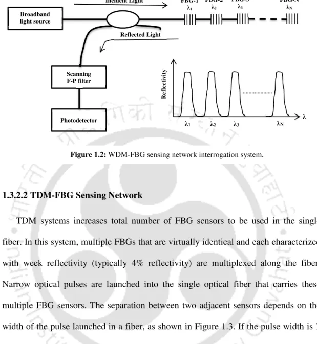
WDM-FBG Sensing Network
The maximum number of FBG sensors along a single fiber in a WDM system depends on the optical bandwidth of a broadband light source, the operating range and optical characteristics of each FBG sensor, and the tuning range of a tunable filter. However, the number of sensors can be increased by using hybrid multiplexing techniques, such as WDM and TDM [88], WDM and spectral profile division multiplexing (SDM) [89], WDM and frequency-shifted interferometry (FSI) techniques [90] .
TDM-FBG Sensing Network
Cross talk can be minimized by using ultra-weak fiber Bragg grating (uwFBG) sensors in the network. To interrogate a large-scale array of uwFBG sensors, various test technologies, such as optical time-domain reflectometry (OTDR) [95], optical.
Real-Field Application of WDM-FBG Sensing Networks
Each channel contained ten serially multiplexed FBG sensors, of which six FBG sensors were used. All FBG sensors were 5 mm long and their wavelengths were separated by 5 nm in the wavelength domain.
Fully Distributed Sensing Network
Based on our detailed study, it is determined that FBG sensing networks have wide applicability in the field of structural health monitoring (SHM). So, in the next section, motivations behind the proposed work are presented along with objectives.
![Figure 1.4: The Rayleigh, Raman, and Brillouin scattering effects in optical fibers [64].](https://thumb-ap.123doks.com/thumbv2/azpdfnet/10342385.0/39.892.173.739.327.630/figure-rayleigh-raman-brillouin-scattering-effects-optical-fibers.webp)
Motivation
Therefore, slow-light π-FBG-based quasi-distributed sensing network is proposed to improve the sensing capability. Finally, a combination of π-FBG sensor and fiber Mach-Zehnder interferometer (F-MZI) interrogation is proposed to develop a high-sensitivity ultrasonic acoustic sensor system.
Thesis Organization
To do this, optical and sensing characteristics of slow light π-FBG are optimized with respect to the lattice parameters (δn, L, α and the apodization profile). Finally, the slow-lighting π-FBG with optimized optical and sensing properties is employed in a five-stage quasi-distributed load and temperature sensing network to analyze its application efficiency.
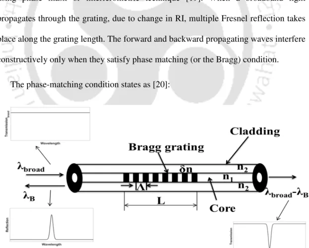
Theory of Fiber Bragg Gratings
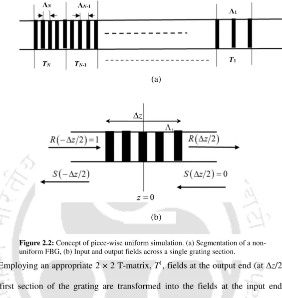
However, in the presence of periodic disorder such as Bragg grating structure within the fiber core, specific guided modes can be coupled. Various techniques have been developed for the analysis of field propagation and the coupling properties in the corrugated structure such as FBGs.
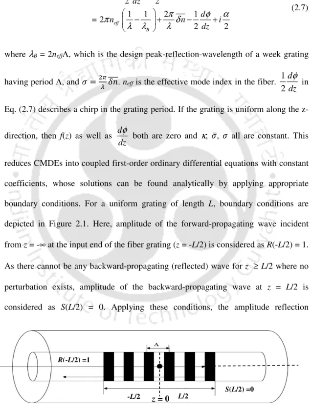
Coupled-Mode Theory (CMT)
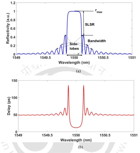
Bandwidth: There are several ways to define the bandwidth for a uniform grating. The easiest definition is the bandwidth between the first zeros on
Sidelobes: For a uniform Bragg grating of finite length, the main peak in the reflection/transmission spectrum is accompanied by a series of sidelobes.
Side-lobes: For a uniform Bragg grating of a finite length, the main peak in the reflection/transmission spectrum is accompanied by a series of side-lobes
Time-delay: The time-delay for the light reflected from the grating is given by
Summary
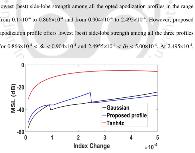
Some of the recently proposed apodization profiles for FBGs and their impact on sensor characteristics for single and multi-point quasi-distributed sensing applications are discussed in Section 3.1. In order to achieve the best optical characteristics of the proposed FBG for quasi-distributed sensing applications, the optimal values of FBG structural parameters such as grating length (L) and index change (δn) are determined. Thus, the FBG with the proposed apodization profile is more important for efficient quasi-distributed sensing applications.
Apodization Profiles
As can be observed from this figure, both proposed and selected elite apodization profiles are symmetric in the middle of the grating length and are normalized such that f(L/2) = 1. The calculated values of aeff for the proposed apodization profile, come the Gaussian profile and the positive Tanh (with a = 4) profile respectively and 0.826 out. Reasons for choosing the Gaussian and the positive Tanh profiles as the elite profiles are the facts that (a) these profiles are predominantly used in grid fabrication, (b) the apodization parameter is observed to be higher than a threshold value of 0.500, hence the effective grating length is not seriously compromised, and (c) apodization parameters for these profiles provide upper bounds as high as 0.826 (for unapodized gratings, aeff = 1.000) and lower bounds as low as 0.522 (within the range of which the comparative analysis makes for the proposed apodization profile in quasi-distributed network more effectively.
Results and Discussion
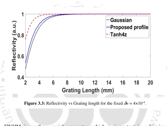
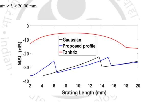
Maximum (peak) reflectivity of the FBG using the proposed as well as selected apodization profiles is plotted as a function of L in Figure 3.3 for a fixed index change of 4×10⁻⁴. The FWHM of FBG spectrum using the proposed as well as selected apodization profiles is plotted as a function of L in Figure 3.5 for a fixed index change of 4×10⁻⁴. The MSL of the FBG using the proposed as well as selected apodization profiles is plotted as a function of δn in Figure 3.6 for a fixed grating length of 10 mm.
Quasi-distributed Sensing Application
To compensate for the internal loss of slow light FBGs, Vigneron et al. However, the dynamic range of the π-FBG is limited by the finite bandwidth of the FBG stopband. This chapter presents a detailed theoretical study of the optical (throughput and delay) and sensing characteristics of slow-light π-FBGs.
Numerical Model of the Slow-Light π-FBG
Compared to the reported highest deformation and temperature sensitivities (4.0 (με)-1 [135] and 22.1 °C-1 [134], respectively), more than twofold increase in deformation sensitivity and more than fourfold increase in temperature sensitivity are achieved by the proposed π-FBG for slow light. It is further observed that the FWHM of the maximum transmission value (passband) of the proposed slow light π-FBG is 0.0798 pm compared to the overall FWHM of 0.2245 nm for its stopband. A dynamic range for strain measurement up to 1469µε and for temperature measurement up to 133 °C is obtained.
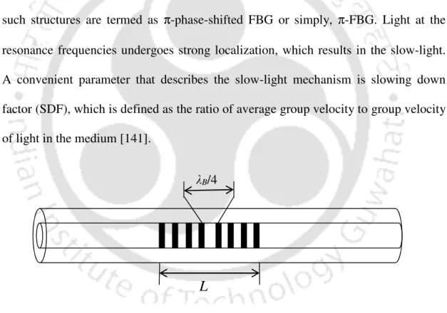
Concept of Slow-light
Interference of the individual components gives rise to the pulse, which is distorted (pulse broadening) as it travels through the medium. One of the simplest ways to achieve slow light is by using FBG, which is characterized by its stopband (centered at the Bragg wavelength) in transmission. Introducing this discrete phase step results in a single ultra-narrow transmission peak (strong resonance), with Lorentzian line shape, within the band transmission peak (strong resonance), with Lorentzian line shape, within the band gap (stop band) of the FBG.
Sensitivity Characteristics of Slow-light π-FBG
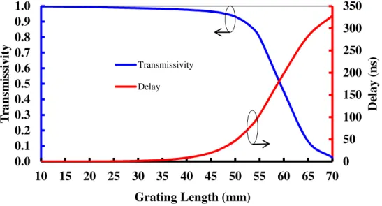
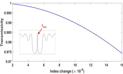
The effect of grating length (L), index change (δn) and the loss coefficient (α) on the optical and detection characteristics of slow-light π-FBG is thoroughly studied. The observed behavior of the optical characteristics (transmissivity and delay) of π-FBG can be explained as follows. In the next part of the study, the effect of grating length (L), index change (Δn) and loss coefficient (α) on the sensitivity of slow-light π-FBG is investigated.
Design and Analysis of Highly Sensitive Ultrasonic Acoustic Sensor based on π-FBG and
As already pointed out in the previous chapter, if the π-FBG is used for sensor applications, a much larger slope of its passband will result in a remarkable increase in sensitivity. However, the maximum path length discrepancy cannot exceed the coherence length of the signal in the fiber. This coherence length is inversely proportional to the bandwidth of the reflected signal from the FBG [151].
Theoretical Modelling
Furthermore, the intensity noise of BLS in the proposed sensing system can be easily eliminated by using a dual-channel F-MZI configuration [ 153 ].
Acoustic-Ultrasonic Wave Modelling
On the other hand, the change in the optical indicatrix (1/n2) due to the elasto-optic effect during the application of tension is given as [7]. Furthermore, change in the indicatrix can be related to a change in refractive index δn by [7]. In the absence of shear stress, the change in refractive index can be obtained by solving the above equations.
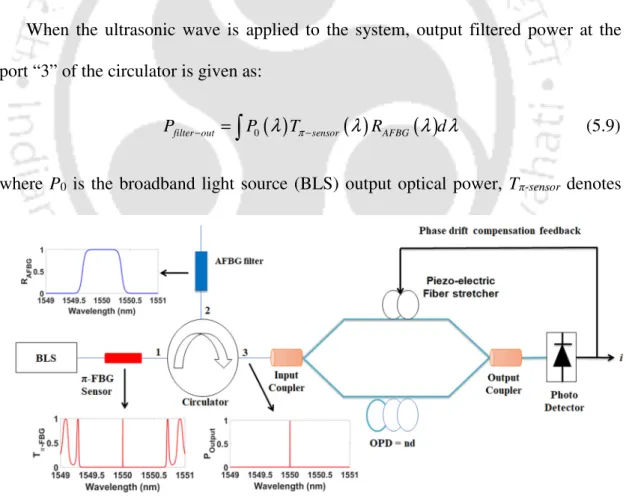
Sensor System Modelling
Phase of the F-MZI changes due to the modulation of the Bragg wavelength of π-FBG by ultrasonic strain wave. Finally, the grating response to the longitudinal ultrasonic (US) perturbation needs to be quantified in terms of the sensitivity of the system. On the other hand, the normalized power sensitivity of the sensor system to the ultrasonic acoustic stress field (Sε) can be derived as.
Numerical Results and Discussion
Further, for the achieved strain resolution of 4.1 fε, a wavelength shift resolution of 4.92×10⁻⁹ pm is easily achieved. A wavelength shift resolution of 3.7×10⁻³ pm is reported in [149] for acoustic emission sensor based on π-FBG and Michelson interferometer. The proposed sensor system shows the highest theoretical strain sensitivity of ε and a theoretical dynamic strain resolution of 4.1 fε/√Hz.
Conclusions and Scope for Future Work
Conclusion
When deploying the proposed grating in a five-stage quasi-distributed sensing network, a dynamic range of up to 131.6 °C for temperature and up to 1450 µε for voltage measurement is obtained. Strain sensitivity as high as 8,380 (με)-1 and temperature sensitivity as high as 91,064°C-1 are achieved for the optimized π-FBG. Furthermore, voltage sensitivity as high as ε and resolution as high as 4.1 fε/√Hz are achieved with the proposed sensor.
Future Research Work
Finally, in chapter 5, a highly sensitive ultrasonic acoustic detection system is developed by using π-FBG and unbalanced fiber Mach-Zehnder interferometer. The interrogation system for slow-light π-FBG-based quasi-distributed sensing networks enabling static measurements needs to be designed and characterized experimentally. The experimental verification of an acoustic sensing system based on π-FBG and unbalanced F-MZI presented in this thesis needs to be performed.
Han, "Fiber optic pressure sensor based on π-phase-shifted fiber Bragg grating on side hole fiber", IEEE Photon. Digonnet, "High-resolution slow-light fiber Bragg lattice temperature sensor with phase sensitive sensing," Opt. Yang, “Highly stabilized phase-shifted fiber Bragg grating sensing system for ultrasonic sensing,” IEEE Photon.
List of publications