H3: Adequate anthropometric and biomechanical compatibility of a handheld floor polishing device can significantly improve the usability of the device. The concept created based on the features of the floor polishing machine was reviewed using a Pugh chart.
Introduction
- Ergonomic stressors in work place
- Health disorders due to occupational exposure to vibration
- Exposure to vibration in construction sectors in Guwahati, Assam
- Design Intervention of vibrating equipment/ device
- Research Gap and justification of the present research
- Research Questions
- Problem Statement
- Aim
- Objectives
- Hypotheses
- Expected outcome
- Organization of the thesis
- Chapter 1-Introduction
- Chapter II Review of Literature
- Chapter III- Methodology
- Chapter IV-Results
- Chapter V- Discussion and Conclusion
Extensive use of vibrating equipment/device is a regular part of the workers in these informal sectors. This chapter also includes the methodology of effective design intervention to reduce the impact of vibration during the use of the handheld floor polishing device.
Literature Review
Introduction
Occupational Exposure to vibration
Construction Sector
In addition, some of the other indicators of the defective hand tools are: (1) Stable stacking of arm and shoulder muscles (2) difficult hand position, mainly wrist divergence, (3) extensive force on the palm and fingers (4) exposure to vibration and cold from power tools (5) pinch points with double-handled tools and (6) handles that require an extension of the hand to grasp or high force to hold (Anderson, 1990). Brainstorming was conducted to generate ideas focusing on the functional need for the floor polishing unit.
Vibrating hand-held tools used in unorganized sector including construction
Adverse impact of vibration on occupational health
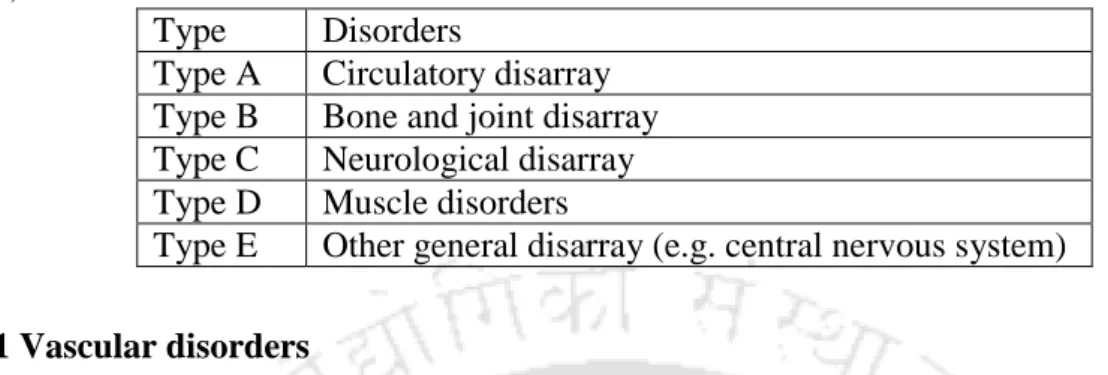
- Vascular disorders
- Neurological Disorders
- Muscular effects, articular disease and other effects
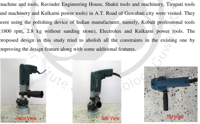
A systematic evaluation of the outcome was performed for design intervention of floor polishing device. To study the existing polishing machines, some of the shops (Kamakhya Machine and Tools, Ravinder Engineering House, Shakti Tools and Machinery, Tirupati Tools and Machinery and Kulkarni Power Tools) in A.T.
Principle of hand tool design
- Ergonomics considerations in hand tool design
- Hand physiology
- Anatomy of hand
- Hand Anthropometry
- Hand Grip
- Design variables for hand-tool design
- Handle Length
- Handle size
- Handle shape
- Handle precision
- Handle material
Product form function
- Working in product concept
Affordance in design process
He argued that we do not perceive points of light; rather, we perceive opportunities for action. He argued that we perceive the affordances of the environment directly and immediately, not indirectly by gathering evidence from our senses.
The concept design process
- Establishing the aims and scope of concept design
- Product function analysis
- Concept selection
- Embodiment prototyping and testing
To simplify the ordering procedure; each concept is rated better than (scored as +1), "worse than" (scored as -1), or "the same as (scored as 0) a reference concept. Provided that at least one of the concepts has a score better than (0) overall, the concept selection procedure must be repeated.
Design Aesthetics
In this "model of aesthetic experience," an observer of artwork begins with a perceptual analysis of the work, compares it to previous encounters, classifies the work into a meaningful category, and then interprets and evaluates the work, leading to aesthetic judgment and aesthetic emotion. In these, mostly automatic stages, perception is at work and the extent to which our perceptual system succeeds in detecting structure and assessing the work's novelty/familiarity determines the effect that is generated.
The management of design risks
The Pugh diagram was used to screen the generated concept based on the functions of the floor polishing device. The vibration exposure level while using the existing portable floor polisher was high.
Basic Definition
- Vibration
- Vibration Types
- Categorization of Vibration by contact site, effect and frequency
- Classification of vibration by magnitude and axes
- Peak, Average or Dose measures
Human Vibration and its characteriztion
- Measurements of Human Vibration
- Standard for assessment of hand-transmitted vibration
- Human Vibration Meter
- Muscular fatigue due to vibration and its quantification
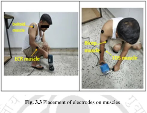
Evaluation of muscular effort during operation of hand-held device
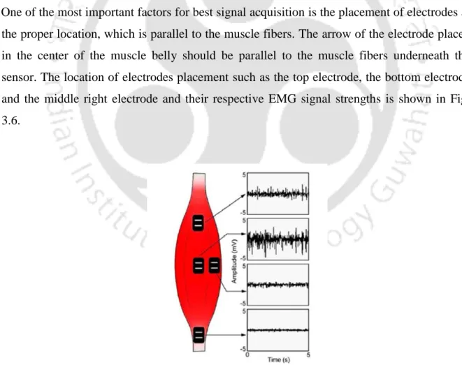
- Surface electromyography
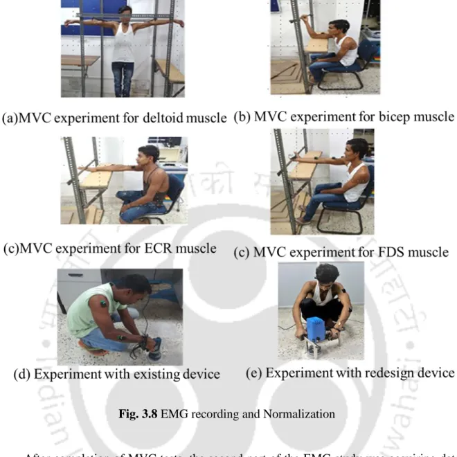
The continuous observation of local muscle fatigue by performing certain work is possible by assessing the myoelectric activity of the specific muscles using the procedure of surface electromyography (EMG) (fig.2.13) (Cifrek et al., 2009 ). The determination of local muscle fatigue is one of the critical parameters in the industrial application of ergonomics. Similarly, to investigate the biceps and deltoids, the effect of overhead drilling on the muscle activity of the muscles was considered (Garapati, 2007).
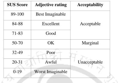
System Usability Scale (SUS)
Methodology
- Location of the study
- Sampling
- Data collection
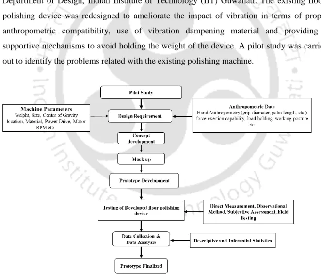
- Research Framework
- The product development process
- Preconceptual phase
- Concept generation
- Pre design and detailed phase
Exposure to excessive vibration while handling the floor polishing device was the main disadvantage of the polishing device. An appropriate development process was followed when redesigning the existing portable floor polishing device. A morphological map was used to combine all the important functions of the floor polishing device with the possible solutions.
Result
Demographic exploration
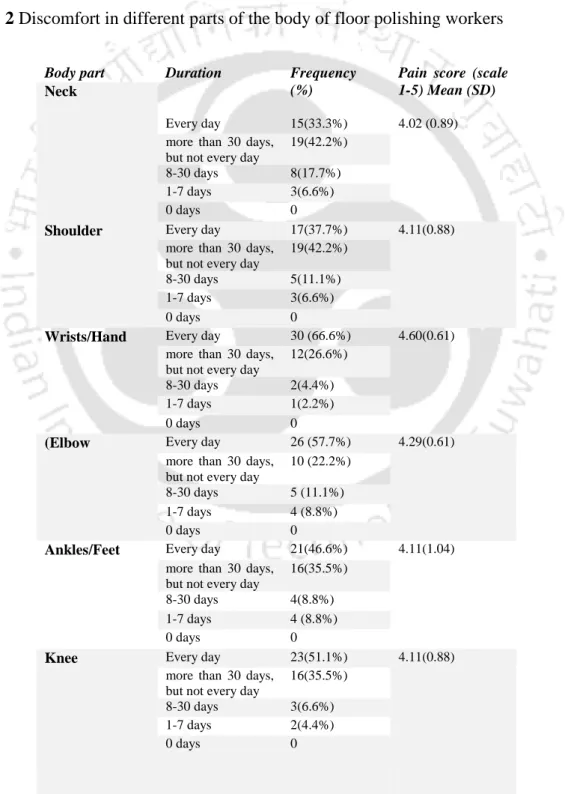
Discomforts in various parts of the body of the polishing workers
The occurrence of discomfort/pain in different parts of the participants' body and thus disruption of their regular activities at the workplace or outside the workplace is shown in Figure 4.1.
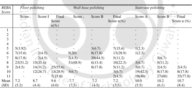
Posture Analysis
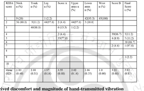
The participants' wrists were in extension (sagittal plane) of up to 15°, and thus the REBA score was 3. The result of the REBA for an individual worker working with the redesigned floor polishing unit at different locations (floor, wall-base and stairs) is shown in table.4.5. In the former case, the wrist score was 3, meaning that the wrists of floor polishers were in extension, whereas the wrist score was +1 for floor polishers who were working.
Perceived discomfort and magnitude of hand-transmitted vibration
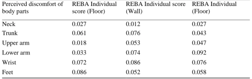
Association between different adopted posture and vibration discomfort
There was an insignificant correlation between REBA scores for individual body parts with the level of perceived discomfort at individual body segments (from the Nordic questionnaire). Likewise, the correlation between the REBA grand score and general perceived discomfort was also found to be insignificant. There was a significant correlation between measured vibration intensity (vector sum) and perceived discomfort at individual body segments or overall body parts (table-4.9).
Existing Design and its Evaluation
4.3 and 4.4 show a simple black box diagram and the functional tree structure of the portable polishing device. Thus, from notation (1, 3) it is deduced that the tubular handle portion is used for conveniently holding the floor polishing device. There was also a significant difference in the required muscle strength while using the existing and redesigned polishing device.
It has a clear device for easy assembly and disassembly of the polishing device with the support frame. What is the current state of numbness, tingling or numbness in fingers, palms.
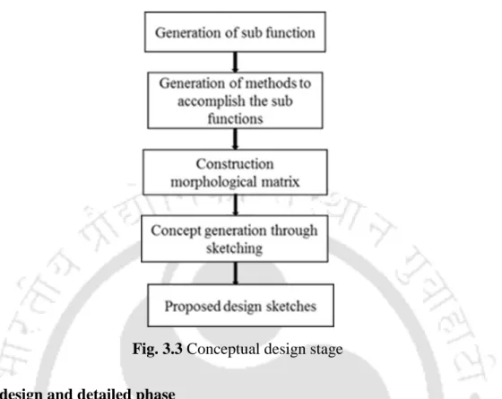
Functional Modelling
Generation of sub-functions
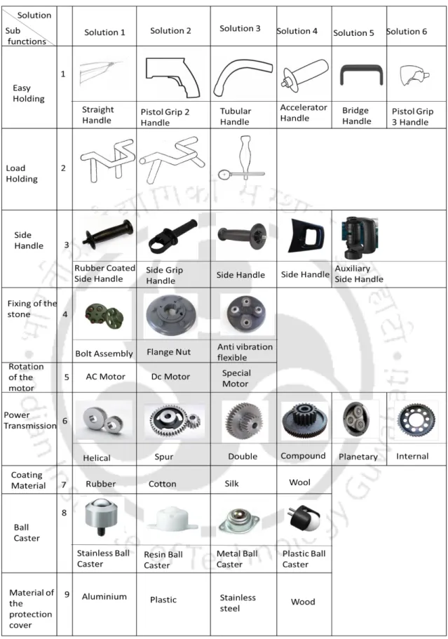
The identified sub-functions contributed to the fulfillment of the total function of the product. The options available for each of the sub-functions are then recognized as sub-components. These sub-components that formed the sub-functions were set in a rational way to fulfill the main overall function of the machine.
Construction of morphological matrix
Then the sub-components required for the developed sub-functions were decided for easy holding, load shedding, etc. Thus, a particular type of fusion outlined in this procedure has eight subcomponents, since there were eight subcomponents to be achieved. These eight subcomponents arranged in the logical sequence were developed into the overall product under study.
Concept generation through sketching
Concept Sketch 1 proposed a tubular handle polishing device with a side handle attached to the body of the device and a ball wheel attached to the main handle for smooth movement. Concept Sketch 7 proposed a single handle design along with a bolt-on side handle with an AC motor. Concept Sketch 9 has a straight handle with side handle that has bolt-on mounting with side handle that has bolt-on mounting, AC motor.
Concept evaluation and selection
- Pugh chart
Existing machine with compound gear trains
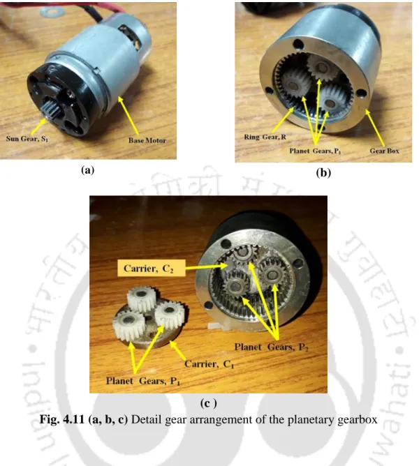
Calculation for planetary gear train
In the transmission shown above, the Carrier, C2 acted as the output shaft of the transmission. By counting the teeth of each gear and taking into account the speed of the Carrier, C2 as 750 rpm, and the speed of the base engine, ie. with a planetary gearbox with 2-speed reduction action, the engine speed was reduced to 750 rpm with a rated torque of 3.9 Nm.
Manufacturing of the components
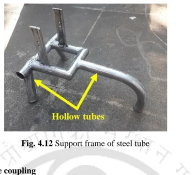
- Support frame
- Polishing stone coupling
- Motor mounting block
- Sliding Blocks
- Guard ring
- Side and back handle
- Coating material
- Spherical Balls (Ball caster)
- Power Supply
The model was tested for its assembly with the stone joint and the engine, which is shown in Fig.4.16. The template was used to extrude the steel pattern as shown in Fig.4.17. The ring acted as a clamp with which the user could adjust the height of the stone in relation to the ground surface.
Assembly of different components of the floor polishing device
- Ball caster assembly
- Handle and grip assembly
- Motor and coupling assembly
- Plastic protection cover with switch and power socket
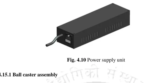
- Power supply unit
Two front legs of the main frame were fitted with spring-loaded ball casters, as shown in Figure. The rear ball caster was attached to the M6 threaded hole in the rear leg of the main frame. The screws for the handle mounting were inserted through the holes on both sides of the main frame.
Raw material cost for a stone polish machine with cover and power supply
The lower section was provided with a cut-out section to which an IEC male socket with fuse could be assembled with snap fit.
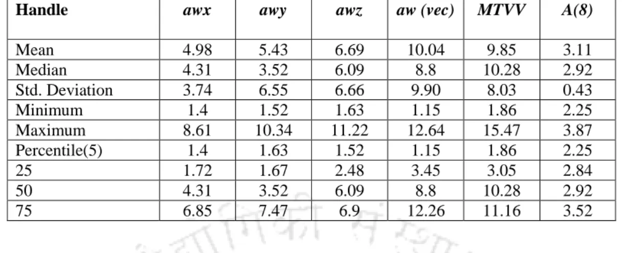
Measured magnitude of vibration
For the redesigned floor polisher, the eight-hour energy-equivalent frequency-weighted acceleration magnitude [A (8)] at the handle for each of the participants was lower than the recommended daily average vibration exposure action value (= 2.5 m/s2), as shown in table. The eight-hour energy equivalent of the frequency-weighted acceleration magnitude [A (8)] at the wrist using the existing floor polishing device for each of the participants was greater than the recommended daily average action value (= 2.5 m/s2), as shown in Table 4.15. While the eight-hour energy-equivalent frequency-weighted acceleration magnitude [A (8)] at the wrist using the redesigned floor polisher for each of the participants was lower than the recommended daily average action value = 2.5 m/s2 as shown in the table 4.16.
Comparative analysis between the existing floor polishing device and the
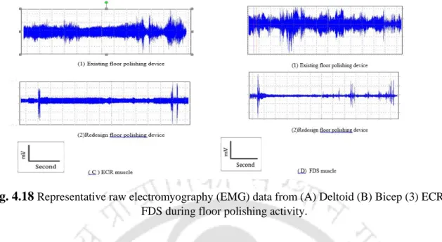
- Electromyography
- EMG (%MVC) selected for selected muscles
This meant that the redesigned device was more than twice as exposed to palm and hand vibrations as the existing one. The purpose of this experiment was to compare the muscle effort in operating an existing and a redesigned floor polishing device (Figure 4.31). A Wilcoxon signed-ranks test was performed to compare muscle strength between the existing and the redesigned floor polisher.
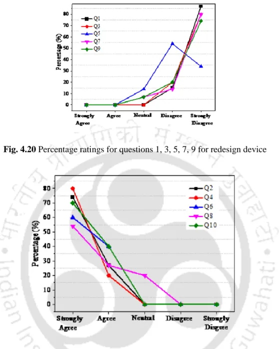
Usability testing
Provision for vertical adjustment of the device to accommodate polishing stones of different thicknesses has been made in the redesigned device. The grip diameter of the existing device was 35 mm and it was covered in hard plastic. The effectiveness of the redesigned polishing device could be studied in terms of other physiological variables such as HR, EE etc.
Discussion and Conclusion
Key Findings
The weight of the redesigned floor polisher is greater than the existing floor polisher (existing device: 2.8 kg and redesigned device: 3.9 kg) due to the addition of the support frame and handles. There was a significant reduction in the generation and transmission of vibrations after redesigning the floor polishing equipment due to changes made to the gear mechanism by replacing the compound gear in a planetary gear. Data collected using the arm vibration meter on the handle of the redesigned floor polishing device and the operator's wrist while using the device, describe that the magnitude of the eight-hour frequency-weighted acceleration [A (8)] per each of the participants was less than the recommended action value (2.5 m/s2).
Key features of the redesigned floor polishing device
The polishing workers participated in the test and feedback of the redesigned device, were satisfied in terms of the quality of polishing on the floor surface. Slots/cuts are provided on the upper part of the cover for proper air circulation required for motor cooling during operation.
Testing of Hypotheses
Workers used to undergo continuous loading (2.8 kg without grinding stone) of the existing polishing device for a long time (8 to 10 hours) during a shift. If it is a newly designed polishing device, the weight (3.9 kg without grinding stone) is carried by the supporting structure on the ground. It could thus be stated that hypothesis- 3: 'Correct anthropometric and biomechanical compatibility of hand-held floor polishing unit can significantly improve the usability of the unit' is accepted.
Novelties (key contributions) of the present research
It implies that designers/engineers should focus on anthropometric and biomechanical data while designing the portable vibrating tool/equipment/device. The present study has focused on the real problems of occupational vibration exposure of floor polishing workers in the unorganized sectors of the construction industry. Depicted here is an appropriate ergonomic design intervention to ease the work of underprivileged construction workers.
Limitation of the present research
Conclusion
Plight of the Construction Workers [online]. Available from https://abdulkazad.wordpress.com plight-of-the-construction-workers-of-guwahati/. Influence of Jackhammer weight on grip pressure, muscle activity and hand-arm vibration of the operator. Dynamic response of the standing human body exposed to vertical vibration: influence of posture and vibration magnitude.
Effects of handle position and feeding force on discomfort score and grip strength during hand drilling. Response of the sedentary human body to vertical whole-body vibration: biodynamic responses to mechanical shock.