0
Friction Stir Welding of aluminum 6082 with mild steel and its joint analyses
Sajin George Sajan
A Dissertation Submitted to Indian Institute of Technology Hyderabad In Partial Fulfillment of the Requirements for
The Degree of Master of Technology
Department of Materials Science and Engineering
July 2012
1
Declaration
I declare that this written submission represents my ideas in my own words, and where others’
ideas or words have been included, I have adequately cited and referenced the original sources. I also declare that I have adhered to all principles of academic honesty and integrity and have not misrepresented or fabricated or falsified any idea/data/fact/source in my submission. I understand that any violation of the above will be a cause for disciplinary action by the Institute and can also evoke penal action from the sources that have thus not been properly cited, or from whom proper permission has not been taken when needed.
Sajin George Sajan
MS10M005
2
3
Acknowledgements
I take this opportunity to express a deep sense of gratitude to my Thesis Supervisor, Dr. Suhash Ranjan Dey, for acting as an advisor and giving me complete support throughout this project work that was really challenging. I also want to thank our Director U.B Desai, for granting the project fund required for the material procurement and other necessities.
Next, I would like to thank Dr. Abhay Sharma for giving me the initial idea, how to approach the problem and allowing me to use the facilities in our Central Workshop, IIT Hyderabad. Also Dr. Ramji’s permission to carry out the job order and operating some machines were highly beneficial for my project work.
I want to acknowledge Dr. Jayachandra Reddy (Research associate, IISc Bangalore), who provided me assistance during the Friction Stir Welding (FSW) and taught me to operate the sophisticated CNC machine. I express my sincere thanks to Professor I. Samajdar, IIT Bombay and ARCI, Hyderabad for giving me sufficient number of slots for using the Scanning Electron Microscopy (SEM) for characterization purpose.
I would really like to thank Sree. Sathyanaryanan and all the workshop staffs in Central workshop, IIT Hyderabad, for the relentless work they have exhibited in preparation of workpieces and tools.
Finally, I want to thank our three Ph.D. Scholars, Mr. Karre Rajamallu, Mr. Palli Srinivas and Mr. M.Z. Ahmed for their utmost dedication in helping me to carry out this project work smoothly and efficiently at our Materials Science & Engineering lab.
My hearty and sincere thanks to everyone who contributed some way or the other for making this research work a success.
Sajin George Sajan
4
Dedicated
to
My Parents
5
Abstract
Energy-saving and reduction in CO2 emission are the two important challenging issues that must be resolved in the coming future. Introducing aluminum components in a standard steel car body or in the hulls of ship brings the reduction in weight of vehicles, thereby reducing the emission.
In this research study, Aluminum 6082 alloy and mild steel were tried to join together (weld) by an eco-friendly and energy efficient technology named as Friction Stir Welding (FSW), which is far advantageous than the conventional fusion welding especially in the case of joining dissimilar materials. As this is a solid state welding process, most of the defects occurring in the molten state of the material could be completely eliminated. Also, welding takes place at low temperature (below the melting point of the material) due to which there is less chance of intermetallics formation at the heat affected region that will eventually degrade the mechanical properties of the weld.
Friction stir welding was carried out at IISc Bangalore, where various welding parameters like, tool rotation speed (rpm), welding speed (mm/min) have been tried to optimize and was able to achieve a suitable range for all parameters of 6mm thick plates of Al 6082 alloy and mild steel.
Plunge depth, tilt angle etc. were optimized initially and kept constant during the proper time of welding. After welding, good samples were selected and small specimens were cut from it perpendicular to the weld direction. Tensile specimens were prepared for doing tensile test and, for finding out the microhardness value across the weld region, specimens were well polished.
Thus, mechanical properties like tensile strength and microhardness of the welded joint were measured with the respective instruments at IIT Hyderabad. Orientation Image Mapping (OIM) by EBSD from SEM was taken along the cross sectional length, showing differences in the grain size due to the variation of heat at different zones. In this research study, significance of placing the material on advancing and retreating sides especially during the welding of dissimilar materials has been brought out clearly, with the help of microstructural characterization technique like Energy Dispersive Spectrometer (EDS) analysis. Specimen for EDS scan was well prepared and mirror polished to achieve proper results. Thereby, dependence of welding parameters including the advancing and retreating sides of the weld, on the mechanical properties of the joint of dissimilar materials was able to demonstrate properly.
6
Nomenclature
SSW – Solid State Welding FSW – Friction Stir Welding FSP – Friction Stir Processing FSSP – Friction Stir Spot Welding Al – Aluminum
Fe – Ferrous
AHSS – Advanced High Strength Steel IMC – Inter Metallic Compound
EDS – Energy Dispersive Spectrometer ETA – Engineering Technology Associates IISc – Indian Institute of Science
EDM – Electric Discharge Machine MTS – Material Testing System
EBSD – Electron Back Scattered Diffraction OIM – Orientation Image Mapping
SEM – Scanning Electron Microscopy
7
Contents
Declaration………..1
Approval Sheet………....2
Acknowledgements……….………...3
Abstract……….………..5
Nomenclature……….………....6
1 Introduction………9
1.1 Background………..………9
1.2 Classifications of Welding……….9
1.2.1 Solid State Welding………...…………10
1.2.1.1 Forge Welding………...………...………..10
1.2.1.2 Cold Welding………..………11
1.2.1.3 Diffusion Welding………..11
1.2.1.4 Explosion Welding…………..………..12
1.2.1.5 Ultrasonic Welding………..………..12
1.2.1.6 Friction Welding………13
1.2.1.7 Friction Stir Welding (FSW)……….14
1.3 Significance and emergence of FSW……….…...15
1.4 Principle of operation……….….……16
1.5 Advantages and disadvantages of FSW………...18
1.6 Importance of this project work: Joining of Al 6082 alloy with Mild steel……….20
1.7 Literature Survey………..21
1.8 Project Objectives……….…22
8
2 Experimental Methods………...….….23
2.1 Sample preparation………..……23
2.2 Experimental set up……….….…...24
2.3 Optimization of welding parameters………..….25
2.4 Sample having Al alloy on the advancing side and steel on retreating side………...…..27
2.5 Specimen preparation………..…28
2.5.1 Specimen preparation for micro-Vicker’s hardness test……….28
2.5.2 Specimen preparation for tensile test………..29
2.5.3 Specimen preparation for Energy Dispersive Spectroscopy (EDS) analysis in Scanning Electron Microscopy (SEM)………..31
3 Experimental results and discussions……….32
3.1 Tensile test……….…..…32
3.2 Microhardness distribution………...……35
3.3 Energy Dispersive Spectrometry (EDS) analysis of the joint interface……….…...37
4 Conclusion and Scope for future work……….40
References……….…..42
9
Chapter 1 Introduction
1.1 Background
Welding is a fabrication technology which joins materials, usually metal alloys, composites or thermoplastics. Generally it is done by melting the workpieces that has to be joined and adding a filler material to form a pool of molten material, that when cools, becomes a strong joint. It should not be confused with soldering and brazing, which involves melting a filler metal (which is having a lower melting point than the workpieces) between the workpieces to form a bond between them. The difference to note here is that the workpieces will not get melted.
History of welding starts from the Bronze Age and the Iron Age itself – forge welding. In 1882, Nikolai Benardos (Russian Inventor) created the first electric arc welding method known as carbon arc welding using carbon electrodes. Final decades of 19th century, brought the invention of Resistance welding, followed by Thermite welding. 20th century welding was in complete favor for industrial applications. Also significant advances in the welding technology started from 1920s, like automatic welding, stud welding, gas tungsten and plasma arc welding. In 1950, diffusion bonding method, and in 1960, electromagnetic pulse welding was proposed. In 1991, Friction stir welding (FSW) was invented in UK and opened up a high quality applications in aerospace and ship building industries throughout the world.
1.2 Classification of Welding
Welding is mainly classified into six types
Gas Welding
Arc Welding
Resistance Welding
Solid State Welding
Thermochemical Welding
Radiant Energy Welding
10
1.2.1 Solid State Welding (SSW)
Solid State Welding (SSW) is a type of welding process which differentiates itself from other welding process that, materials which have to be joined will not undergo melting (remain solid state). In SSW, the material fabrication temperature does not reach its melting temperature;
rather the material is heated to a temperature which allows the plastic deformation to occur easily. As there is no melting, many problems associated with traditional fusion welding like segregation, severe residual stresses, distortion and evaporation of volatile elements are avoided to a greater extent. Here, the process parameters like time, temperature and pressure individually or in combination produces coalescence (joining) of the base materials. It should be taken care that the operating temperature should always be below the melting point of both the workpieces and the bonding of the materials is mainly due to the diffusion of their interface atoms.
Classifications of some important SSWs are given below [1].
1.2.1.1 Forge Welding (Hammer welding)
It is the first SSW, which joins the materials by heating them (normally up to 1000oC) in a forge and applying pressure or blows sufficient to cause permanent deformation at the interface.
Materials become plastic state inside the forge and then blacksmith by skillful use of hammer along with anvil was able to create pressure at the faying surfaces sufficient to cause coalescence. Prior to forge welding, the parts are scarfed in order to prevent entrapment of oxides in the joint. This process is less significant to industries now.
Advantages
Good quality weld can be obtained
Parts of intricate shape can be welded
No filler material is required Disadvantages
Only low carbon steel can be welded
Highly skilled operators are required and very slow process
Weld may be contaminated by the coke used in heating furnace
11
1.2.1.2 Cold Welding (CW)
It is a SSW process, in which workpieces are joined together at room temperature, and under high pressure, causing a good amount of deformation and giving an intimate contact between the welded surfaces. Sufficient pressure can be achieved by simple hand tools for joining thin materials and a huge press for heavier sections. Process is readily adaptable for joining ductile materials like aluminum, copper, nickel alloys, low carbon steels etc., in which Al and Cu can be readily cold welded. It is widely used in corrosion protection coatings by manufacturing bi-metal steel–Al alloy strips, cladding of Al alloy strips by other Al alloys or pure Al.
1.2.1.3 Diffusion Welding (DFW)
In diffusion welding, coalescence of the faying surfaces is produced by the application of heat and pressure. Filler may or may not be used. Bonding of the materials occurs as a result of mutual diffusion on their interface atoms. Process is mainly done in vacuum, in order to keep the faying surfaces clean from oxides and other air contaminations. Dissimilar materials like steel to tungsten, niobium and titanium are mainly welded in which a filler layer of a different metal is often sandwiched between the two base metals to promote diffusion. This process is primarily used in aerospace and rocketry industries, electronics, nuclear applications and manufacturing composite materials.
Advantages
Dissimilar materials can be welded
High quality welds are obtained
There is no limitation for the thickness of workpieces Disadvantages
Time consuming process with low productivity
Good surface preparation is required prior to welding
Initial investment for the equipment is high
12
1.2.1.4 Explosion Welding (EXW)
In Explosion welding, a rapid coalescence of two metallic surfaces is caused by the energy of a controlled detonated explosive charge. Though heat is not applied in making an explosion weld, it appears that metal at interface is molten during welding. This heat comes from the shock wave associated with impact and from the energy expended in collision. This welding creates a strong weld between almost all metals and dissimilar metals like (Cu, Ni, W, Ti to steel, Cu-Al), which are difficult or non-weldable by arc process. The process is self-contained, portable and welding can be achieved quickly over large areas. The strength of the weld joint is equal to or greater than the strength of the weaker of the two metals joined. It is used for manufacturing clad tubes and pipes, pressure vessels, aerospace structures, heat exchangers, ship structures, corrosion resistant chemical process tanks.
Advantages
Can weld large surfaces
High quality bonding: high strength, no distortions, no porosity and no change in microstructure
Low cost and simple process, surface preparation is not required.
Disadvantages
Brittle materials cannot be joined
Only simple shapes like plates and cylinders can be bonded
Safety and security aspects of storage and using explosives
1.2.1.5 Ultrasonic Welding (USW)
This is also a SSW process which produces coalescence by the local application of high frequency vibratory energy as the work parts are held together under pressure. Ultrasonic tip or electrode is clamped against the workpieces and is made to oscillate in a plane parallel to the weld interface, by which the welding occurs. The combination of clamping pressure and oscillating forces produces dynamic stress in the workpieces which produce small deformations that raise the temperature in the base metal at the weld zone. This temperature and clamping pressure helps in the joining of interface. Weld strength is normally equal to the base metal.
13 Ultrasonic cycle takes about 1 sec and the frequency of vibrations is in the range of 20-70- KHz.
This welding is useful for bonding small workpieces in electronics, for manufacturing communication devices, watches, automotive industry etc.
Advantages
Dissimilar metals can be joined
High quality weld can be obtained Disadvantages
Only small and thin parts can be welded
Equipment and workpieces may fatigue at the reciprocating loads provided by ultrasonic vibration
1.2.1.6 Friction Welding (FRW)
Here the coalescence of the materials is produced by the heat obtained from mechanically induced sliding motion between rubbing surfaces. The work parts are held together under pressure. Here one part is rotated against another to generate frictional heat at the junction and once a suitable high temperature is reached, rotation is stopped and additional pressure is applied and joining occurs.
Advantages
Ability to produce high quality welds in a short cycle time
No filler metal is required and flux is not used
Can be used to join dissimilar materials and also welding thermoplastics Disadvantages
Friction welding requires relatively expensive apparatus similar to a machine tool
Optimization of the welding parameters like rotational speed (decides the temperature), pressure between the two parts, welding time etc. are tough to deal with
Only cylindrical workpieces can be joined
It is generally used to join light-weight aluminum stock to high strength steels in aerospace, bi- metal joints in nuclear industry, copper-steel joints in reactor cooling systems, joining aluminum alloys to stainless steels and nickel alloys for cryogenic fluid piping and contaminant vessels.
14
1.2.1.7 Friction Stir Welding (FSW)
FSW is an innovative solid-state joining process invented and patented by Wayne Thomas at The Welding Institute (TWI), United Kingdom in December 1991 [2]. In FSW a non-consumable rotating cylindrical tool with a shoulder and a specially designed pin, harder than the material to be welded is inserted into the butt lines of the base metal plates and subsequently travelled along the joint line [3] (Fig.1). Frictional heat generated due to the rubbing action of tool-shoulder part against the work piece makes it soft and plastically deform, and the rotation and transverse movement of tool-pin part facilitates the joining along the interface line of two pieces.
Figure.1. Schematic diagram of Friction Stir Welding (FSW) [14]
Based on FSW, another process called Friction Stir Processing (FSP) was developed which is also a solid state process that has the ability to modify microstructures and provide improved properties over conventional processing technologies in the local areas on the surface layer of metal components [4]. Though both shares the same type of mechanism, the main difference between two technologies is that, aim of FSW is to join two plates together, while FSP aims at modifying the microstructure of a single workpiece or multiple workpieces. In FSP, the tool moves along specially designed paths. Its application involves processing of new metallic alloys
15 or composites in energy field like for e.g. process or join vanadium alloys and nanoparticle reinforced copper composites for the fusion reactor [5]. It can be also used for the processing of polymeric materials and composites, but there is a small concern that the severe plastic deformation that takes place in the nugget zone can break the macromolecular chains and change the properties of the materials. Tool wear during processing, increasing the joint strength and improving the fatigue property of the composite materials are the major challenges that are facing FSP today.
Friction Stir Spot Welding (FSSP) is another technology, which creates a spot, lap-weld without bulk melting. It is more advantageous than electric resistance spot welding (RSW) in welding new high performance light weight structural materials such as Al alloys and advanced high strength steels (AHSS), which are highly used for automobile manufacturing [6]. Due to the extremely high cooling rate in RSW, the weld region of AHSS would develop highly brittle microstructures and is prone to solidification related weld cracks/defects, which never happen in FSW.
1.3 Significance and emergence of Friction Stir Welding (FSW)
Initially the process FSW was regarded as a laboratory curiosity, but soon it became clear that the process had much to offer in welding of aluminum alloys. With this FSW emerged as a joining technique in the early 1990s with the ability to form high strength aluminum alloy joints that has been used in transportation sectors [31]. In aerospace applications, high strength, fatigue and fracture resistant Al alloys – 2xxx and 7xxx series were the best materials to serve the purpose. These Al alloys were non-weldable because of poor solidification microstructure and porosity in the fusion zone, so were unable to be used in the aerospace industries [30]. During fusion welding, there has been a significant loss of mechanical properties in the weld as compared to the base material. Resistance welding was an option, but was limited due to expensive surface preparation, as surface oxide formation was a major problem. Conventional arc welding process liquefies the workpiece resulting in large grain size and large residual stresses upon cooling, which degraded the material properties. Also the use of filler material changes the joint composition and adds weight in to it. Riveting requires the addition of mechanical fasteners that again increases the weight. Degradation of tensile properties and
16 fatigue life were the main outcome of it. Decrease in strength and increase in weight are very critical for aerospace and transportation industries. FSW was able to successfully weld these Al alloys, without all these defects with remarkable joint strength.
Now there is an active development to widen the scope of the process to thicker Al alloys, more complex shapes and other materials (ferrous and non-ferrous). There is an increasing interest in welding copper, titanium, steel, nickel, magnesium etc. as well as in welding dissimilar material combinations. Except Al and Mg, all other materials have high melting point, so higher the operating temperature and hence, there will be additional demand on the material and design of tool, which is highly important [7]. For example, steels and stainless steels can be joined efficiently only by using the hardest known tool materials like Tungsten Carbide (W-C) and Tungsten Rhenium (W-Re)/ Poly Cubic Boron Nitride (PCBN) respectively. W-C is cheaper while W-Re and PCBN are highly expensive [INR 2-3 lakhs per tool].
Today, development of the FSW process is underway in many companies, research institutes and universities around the world, and the growth is rapid [8]. The ship building and marine were the first two industries to adopt the FSW process for commercial applications, followed by aerospace, railway, automotive, construction, and recently by nuclear [9] and electrical industries - especially as Micro Friction Stir Welding (MFSW) [32].
1.4 Principle of operation
Friction Stir welding (FSW) is a Solid State Welding (SSW) process in which a non-consumable rotating cylindrical tool with a profiled probe is slowly plunged into the joint line between the two workpieces, which are butted together. This probe (pin) protrudes from the base of the tool (shoulder). The length of the pin is slightly less than the thickness of the workpiece or the weld depth required and the shoulder should be in intimate contact with the workpiece surface. The workpiece has to be clamped on a backing plate to arrest all the three dimensional movements.
The side of the weld in which the rotating tool moves in the same direction as the traversing direction is known as the advancing side, and the side in which, rotation of the tool takes place opposite to traversing direction is known as the retreating side.
17 The frictional heat is generated mainly by the high normal pressure and shearing action of the tool shoulder over the material. This heat causes the workpiece material to reach the plastic state (soften) without reaching its melting point and makes the tool easy to traverse along the joint line. As the tool rotates, the probe will be surrounded by a softened zone of the material which cannot escape as it is constrained by the tool shoulder. When the rotating tool plunges into the workpiece, pin displaces some material and a cavity is created in the base material within the tool shoulder. The shape of the cavity is decided by the pin profile. At this stage there is a plasticized material around the pin and below the shoulder shown in the Fig. 2. as extrusion and forging zone. This material serves as the start of a reservoir for the forging action of shoulder.
Forward movement of the tool brings the material from the front (leading edge) to back (trailing edge) of the pin into this cavity, pushing the existing material into the flow of the pin. Proper operation of this shoulder design requires tilting the tool 20 - 40 from the normal of the workpiece away from the direction of travel; this is necessary to maintain the material reservoir and to enable the trailing edge of the shoulder tool to produce a sufficient compressive forging force on the weld [10].
Figure. 2. Schematic diagram showing the principle of operation of FSW [10]
Friction Stir Welding and Processing: Rajiv S. Mishra, Murray W. Mahoney; page 47
18 Material flow from the leading edge to the trailing edge occurs by two different modes, namely shoulder and pin driven flow [11]. In the shoulder driven flow, material flows from the retreating side and forges against the advancing side and in the pin driven flow, material flows layer by layer around the pin, and the layers are stacked in the weld line. Frictional heat from the tool shoulder is considered to be the primary heat source and the deformation heat from the tool pin to be the secondary heat source [12]. FSW can be thought of as a process of constrained extrusion under the action of tool. One of the interesting phenomena in FSW is the formation of ring pattern shown in the figure below. Fratini et al and Krishnan pointed out that the formation of onion ring is a geometric effect and they stated that the semi-cylindrical sheets of material are extruded during each rotation of the tool and cross sectional slice through it results in the onion ring pattern [11]. The welding of the material is facilitated by severe plastic deformation in the solid state involving dynamic recrystallization of base material [13].
1.5 Advantages and Disadvantages of FSW Advantages
Solid phase joining technique: As there is no fusion (melting), problems related to liquid phase like segregation, porosity, cracking and solidification cracking in 2xxx and 7xxx Al alloys are eliminated. Also there is no fume and spatter during the process.
Automated machine control: CNC milling machine for FSW itself is automated, giving quality weld. This removes the traditional welding skill of the operator.
Retainment of material property: As there is no loss of alloying elements, and low operating temperature, there will be no significant change in the property of the base material.
Low distortion and shrinkage: Distortion is almost negligible especially in materials like Al compared to fusion weld.
Absence of shielding gas and filler material: For most of the materials (Al, Mg, Cu) shielding gas is not all required. For materials having high melting point i.e. weldability at high temperatures, inert shielding gas improves the surface finish and increases the tool life. Shielding gas is mandatory for welding titanium alloys as Ti oxidizes rapidly [15].
FSW can be operated underwater also [16, 17].
19
Excellent mechanical properties: Mechanical properties of the weld region of similar material weld are equal or higher than the base material and far better than the fusion welds. But in dissimilar weld, strength of the weld zone will be less than the strength of the weaker base material [19].
Hydrogen contents of the FSW joints tend to be low, which is very important in welding steels and other alloys that are susceptible to hydrogen damage.
FSW equipment is simple, user-friendly and relatively of low running cost.
Green technology: Absence of green-house gases, UV or electromagnetic radiation hazards, makes it eco-friendly and energy efficient technique.
Disadvantages
Welding speed: Slower welding speed than some of the fusion welding process and laser welding process for thin sections.
Workpiece clamping: When the tool plunges into the weld line, it will try to separate the two pieces. Also due to the pressure exhibited by the shoulder, workpieces will revert back. So proper jigging, fixtures and backing bars are essential to prevent the abutting of the plates in all three dimensions.
Exit hole: A keyhole will be always left at the end of each weld when the tool is withdrawn. This can be eliminated by providing an offset in the path for continuous path or moving into an extra sheet of material for non-continuous path, from which the tool is allowed to come outside and then cut away the excess part. Another method is slow removal of the tool during welding itself and before the end of weld, tool comes out fully so that there will be no exit hole.
Optimization process: Optimization of process parameters like tool rotation speed, welding speed, plunge depth, tool geometry, dwell time etc. is really a challenge as each of these parameters are dependent on each other in determining the sufficient heat generation that finally decides the strength of the joint.
Less flexible than manual and arc welding process due to the difficulties in varying thickness of the materials and also in non-linear welds.
20
1.6 Importance of this project work: Joining of Al 6082 alloy with mild steel
Energy-saving and reduction in CO2 emission are the two important challenging issues facing our world today. One of the effective counter-measures is the reduction in weight of automobiles that contributes to the maximum pollution. It is estimated that 10% of vehicle weight reduction results in 8–10% of fuel economy improvement [18]. Nowadays, generally the vehicle weight reduction is achieved by (a) replacing the high density conventional steel by new aluminum alloys and/or (b) by using advanced light weight high strength steels. As cost is a problem for both of the above mentioned methods, there is a huge demand for joining conventional steel and aluminum alloys, in vital parts of vehicle like chassis module, doors, trunk lid etc. So introduction of aluminum components in a standard steel car body is an attractive compromise between cost and performance. The main reason behind the selection of Al 6082 alloy in this project is that it is widely used in shipbuilding. Aquatic transportation vehicles prefer hulls made of steel and aluminum alloys, in which they make bottom part below the water surface-steel and above the water surface- aluminum alloys; to lower the center of gravity for stability, as well reduction in the overall weight of ship [19].
The diverse physical properties like melting point, thermal conductivity of steel and aluminum, makes it difficult to join, especially by conventional fusion welding, as it will introduce welding defects like solidification and liquation cracks, porosity, intermetallics etc. due to high temperature. Besides, there is low solid solubility of Fe in Al, which eventually leads to the formation of brittle intermetallic compounds (IMCs). As FSW is basically a solid state welding having a low operating temperature compared to other fusion welding, it is simple to join steel and aluminum, and improve the potential of coupling aluminum parts to steel in vehicle bodies, and has other wide range of industrial applications. Thus FSW has been one of the most significant developments in the last two decades because of its eco-friendliness, energy efficiency, versatility and original metal characteristics will remain unchanged as far as possible.
21
1.7 Literature Survey
First and the foremost investigation have done by T. Watanabe, who showed that the best feasible ways to join steel and aluminum alloys is by Friction Stir Welding (FSW) [20]. He was able to join 2-mm thick plates of steel and aluminum alloy and has obtained a joint tensile strength of about 86% of that of aluminum base metal [21]. Chen and Kovacevic have demonstrated the joining of Al 6061 alloy and mild steel plates having 6-mm thickness by the combined effects of fusion and solid state welding. Tool material used was some kind of tool steel that was inappropriate, and hence significantly worn out during welding [22]. After that, Kovacevic with Jiang was able to obtain a steel-aluminum weld having higher average hardness value than the base metal aluminum. In this experiment, intermetallic compounds and blocky steel particles were observed by them at the weld region (nugget). Tool material H 13 tool steel was used here, which was far better than the previous study [23]. Thaiping Chen afterwards clearly observed various sizes of steel fragments in the entire region of nugget (weld). He has evaluated the Micro-Vicker’s hardness data, tensile strength and the impact value of the weld joint. The joint had a tensile strength of 76% of the 6061 aluminum alloy base metal [24]. Aleš Franc identified six different phases in the binary phase diagram of Fe-Al system, which was considered to be the intermetallics [25]. Another group of researchers in Japan has observed that, the formation of large amounts of intermetallic compounds will drastically degrade the mechanical properties (tensile strength) of the welded joint. They found out that by changing the welding parameters, especially rotation speed, heat input gets changed, that led to the variation of IMC thickness in micrometer range. They have noticed that IMC thickness less than 0.1 µm, gave a maximum tensile strength and when it went above, its strength got reduced [26].
Complete microstructural analysis of the interface (weld zone) has been done on the inertia friction stir welds by another group of researchers [27]. Recently, researchers done a detailed analysis of how, Inter metallic compound (IMC) layer of distinct thickness and composition (obtained by heat treatments), influence the mechanical properties of dissimilar joints of 2-mm steel and Al alloy (with and without Si) [28].
22
1.8 Project Objectives
(1) To find the suitable welding parameters for joining Al 6082 alloy and mild steel of 6 mm thickness and obtain a good weld joint.
(2) Orientation Image Mapping (OIM) for getting the grain size of the severe plastically deformed grains at the welded zone area and at the base side region, and comparing it with the micro-hardness distribution graph along the cross-section perpendicular to the weld direction.
(3) To bring out the significance of advancing and retreating sides in dissimilar welding.
A comparative study by finding out the hardness and tensile strength of the welded joint for the above mentioned two cases.
(4) To find out whether Al moved into steel or vice-versa by Energy Dispersive X-ray (EDS) analysis, and the reason for the sudden increase in the mechanical properties of the friction stir welded joint, when Al was kept in the advancing side of the weld.
23
Chapter 2
Experimental Methods
2.1 Sample preparation
Workpiece materials were mild steel and aluminum 6082 alloy. Initially samples of dimension (110 mm x 50mm x 6mm) were cut approximately from the bulk material by using a hard cutter.
After that, using precision cutting machine, edge face of each samples that has to be joined are cut accurately to the above required dimension. Then the face portion was polished well up to 500 grid paper. Surfaces have to be polished well before friction stir welding for getting good quality weld. Small pores or holes may lead to inhomogeneous mixing and poor weld strength.
Tool material used for the experimental purpose was AISI 4140 tool steel [19] having a cylindrical pin (Fig. 3). Dimensions are shown below. Five tools of same dimension were manufactured with the help of lathe machine in the central workshop (Mechanical department) of our college. After that, it was hardened to 55 HRC in a salt bath furnace. Once it is hardened it becomes brittle and hence cannot be re-machined. So before hardening, tool has to be made in exact final dimension.
Figure. 3. AISI 4140 tool steel Pin
Shoulder
Shoulder diameter (SD) – 25 mm Pin diameter (PD) – 6 mm Pin length (PL) – 5.8mm
24
2.2 Experimental setup
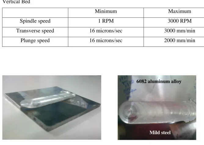
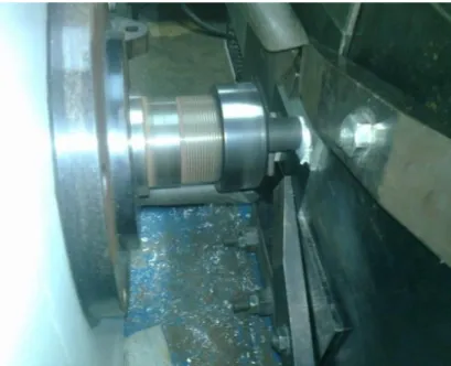
Experiments in this study were performed on ETA Friction Stir Welding machine (specifications given in Table 1) at Indian Institute of Science (IISc), Bangalore. Both aluminum 6082 and mild steel (110mm x 50mm x 6mm) was butt welded (Fig. 4) using 7 kW horizontal head milling machine (Fig. 5). Chemical compositions of the work pieces are given in Table 2.
Table 1: ETA Friction Stir Welding Machine Specifications Capacity: 10 Tones
Vertical Bed
Minimum Maximum
Spindle speed 1 RPM 3000 RPM
Transverse speed 16 microns/sec 3000 mm/min
Plunge speed 16 microns/sec 2000 mm/min
Figure. 4. Friction stir butt welded sample of Al 6082 alloy (white colour) and Mild steel (black colour)
6082 aluminum alloy
Mild steel
25 Figure. 5. FSW Machine at IISc Bangalore showing fixture and horizontal feed
Table 2: Nominal chemical composition of 6082 Al alloy and mild steel
6082 Al alloy Cu 0.1 Mn 0.7 Mg 0.8 Cr 0.25 Zn 0.2 Ti 0.1 Si 1.0 Al balance
Mild steel C 0.18 Mn 0.75 S < 0.05 P < 0.04 Fe balance
2.3 Optimization of the welding parameters
One of the main difficulties, we encounter in a FSW is the optimization process. Different parameters like tool rotation (rpm), welding speed (mm/min), tool plunge depth (mm), axial force (N), tool design etc. are involved in deciding the adequate heat generation for the effective (quality) solid state joining of materials [29]. Here in this case (dissimilar welding); offsetting is an important factor that drastically determines the strength of the joint [21]. Offset (1mm), axial force (7 KN) and tilt angle (3 degree) were kept constant for the FSW machine. Plunge depth
26 was little bit varied and 0.15 mm was obtained to be sufficient for the proper weld joint. A higher plunge depth, greater than 0.15 mm, resulted in pin rubbing against the backing plate surface.
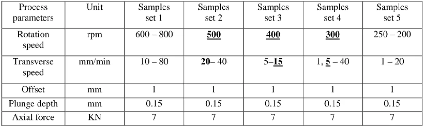
Below, from the Fig.6, (a, b, c) are the samples coming under set 1 (Table 3). These two sets were found to be the extreme limits of heat generation. That is within this sets, heat generation was sufficient for the proper joint. Sample ‘a’ was not joined due to the high welding speed in the range of 60-80 mm/min. If the welding speed is higher, there will be insufficient heat generation for the plastic deformation to takes place and hence it was not joined. For sample ‘b’
and ‘c’ rpm was the higher, and it was observed that, above 500 rpm tool rotation, for any welding speed (mm/min), steel and Al 6082 alloy was unable to join. This is due to overheat generation caused by high rpm of the tool, which caused melting of Al alloy leading to reduction in joint strength. In set 5, when the rpm was kept below 250, due to the insufficient heat generation, material was not reaching to plastic state and was not joined.
Figure.6. Process optimization steps from a-f
c d
e f
a b
27 As when it reached to 500 rpm and welding speed around 20 mm/min somewhat material started to join. Sample ‘f’ (400 rpm and 10 mm/min) from set 3 was joined well as there were no welding defects as far as observed with naked eye and had the highest strength of all the samples from the sets, in steel kept in the advancing side. Set 4 samples were also welded properly with 300 rpm and 5 mm/min welding speed. So a range of tool rotation from 300-500 rpm and welding speed of 5-20 mm/min was found suitable for the quality joint. First half of the sample‘d’ (from set 2) was given a plunge depth of 0.1 mm, in which the shoulder was not able to touch properly and when a plunge depth of 0.15 mm was given in the second half, the pressure was sufficient enough to make the shoulder touch the surface properly that provided good amount of forging force that eventually resulted in good joint. When a plunge depth of 0.2 mm was given, pressure became so high that tool pin began to rub against the backing plate at the bottom part of the workpiece. Two problems occurred: (a) tool wear and (b) workpiece began to get joined with the backing plate.
2.4 Sample having aluminum alloy on the advancing side and steel on the retreating side
Most of the references mentioned in the literature review have steel kept on the advancing side and Al on the retreating side. Often researchers have tried to keep the hard material on the advancing side and soft material on the retreating side. T. Watanabe clearly demonstrated in his
Table 3: Aluminum was kept on the retreating side and steel on the advancing side and the figures (bold and underlined) shows the weld that was successful.
Process parameters
Unit Samples set 1
Samples set 2
Samples set 3
Samples set 4
Samples set 5 Rotation
speed
rpm 600 – 800 500 400 300 250 – 200
Transverse speed
mm/min 10 – 80 20– 40 5–15 1, 5 – 40 1 – 20
Offset mm 1 1 1 1 1
Plunge depth mm 0.15 0.15 0.15 0.15 0.15
Axial force KN 7 7 7 7 7
28 paper [21] that welding cannot take place when a soft material (Al) was kept on the advancing side and a hard material (steel) on the retreating side. But for other materials in the literature, in one of the paper [30], 2024 Al alloy which is softer than 7075 Al alloy, when kept on the advancing side, led to enhancement of the tensile properties and there was a reduction of tensile properties when 2024 Al alloy kept on the retreating side. This shows that welding can of course takes place when a softer material is kept on the advancing side and perhaps there is a chance of improving the mechanical properties also. So just for experimentation purpose, one sample was welded keeping Al on the advancing and steel on the retreating side. Above mentioned optimized range was adopted for this sample (300 rpm and 5 mm/min). Lower range rpm was selected as there is a chance of temperature coming close to the melting point of Al as it was in the advancing side. Surprisingly, there was a drastic change in the analysis of the result which will be discussed in the next chapter.
2.5 Specimen preparation
Samples were cut perpendicular to the weld line with the help of precision cutting machine to a dimension of (60 x 10 x 6) mm and the cross sectional surface of the sample was ground and polished initially by 180 and 500 grit papers. Grinding and polishing have been done rigorously then with 1000, 1200, 1500, 2000 grit paper for getting much smoother and well-polished surface. Up to this much was done for both microhardness and tensile test.
2.5.1 Specimen preparation for Vicker microhardness test
For microhardness testing, 9 and 6 micron colloidal diamond solutions were used for getting somewhat mirror like finish for the surface. Scratches in the samples were avoided maximum to get correct hardness value, when the indenter is pressed against the specimen. Vicker’s Hardness test machine was used for measuring the hardness value. 50 g was employed at the aluminum side and 100 g at the steel side for getting sufficient indentation that could be measured by capturing every indented image by camera having auto-focusing ability. The measurement was started from aluminum side and when the interface is reached, weight was changed to 100 g and then continued in the steel region. The intent was done at 1 mm gap, so an average set of 50
29 readings were able to take along the cross section of 60 mm length specimen. Rest 40 mm length (both sides) out of the total 100 mm length was base metal region that was unaffected by the heat generated by the rubbing of shoulder against the workpiece. Then these values were plotted in excel sheet to obtain the graph with cross sectional length of sample (mm) along the X-axis and microhardness value (HV) along the Y-axis.
2.5.2 Specimen preparation for tensile test
Tensile specimens of required dimension (Fig.7) were prepared with the help of Electric Discharge Machine (EDM) (Fig.8). Dimension of the tensile sample is clearly shown below schematically (Fig.9). Tensile test was able to carry out in Material Testing System (MTS) shown in Fig.10, in which specimen was shown kept in between the fixed grips, before the start of experiment. Minimum value of the grip separation was 1 mm and maximum value can go up to 12 mm. In our case, sample thickness was 6 mm, hence was easily done. This machine can be used for both tension and compression test, and as well as fatigue test. When the tension test is performed, the specimen is pulled by the grips; the elongation and the corresponding stress were calibrated in the computer system in control with it. A stress-strain graph was obtained in the system and thus we were able to determine the yield and tensile strength of the welded joint and with the extensometer attached, we can measure the percentage elongation also.
Figure. 7. Tensile specimens cut from EDM
30 Figure. 8. Electric Discharge Machine (EDM)
Figure. 9. Schematic of tensile specimen (All dimensions are in mm)
31
Figure.10. Material Testing System (MTS)
2.5.3 Specimen preparation for Electron Backscatter Diffraction (EBSD) and Energy Dispersive Spectroscopy(EDS) analysis in Scanning Electron Microscopy (SEM)
Before working in SEM, specimen has to be carefully prepared and polished. Mirror-like polishing is what required for getting a clear scan or image in SEM. To obtain that, various diamond colloidal solutions from 9, 6, 3, 1 micron and then OPS was used. At every interval specimen needs to be observed under the optical microscope for finding any scratches that has to be eventually removed. Generally hard material is easy to polish as there is less chance of getting scratch while polishing. Soft material like aluminum on the other hand is very difficult to get a mirror polishing. In this case, as there was both Al and steel joint, it was very difficult to polish especially at the interface. The main problem was that during polishing the steel particle will come and make aluminum side prone to scratches. So firstly, hard polishing cloth was used with 9 to 1 micron solution to polish the steel side and after that soft polishing cloth was used with similar colloidal solution to polish the aluminum side. Almost scratch free surface was obtained for examining under SEM. Both EBSD and EDS were measured by the SEMs at IIT Bombay and ARCI Hyderabad respectively, and were further analyzed with their related software. SEM- EBSD provided the microstructure-orientation details and SEM-EDS generated the chemical composition results from the region in and around the interface.
32
Chapter 3
Experimental results and discussions
3.1 Tensile test
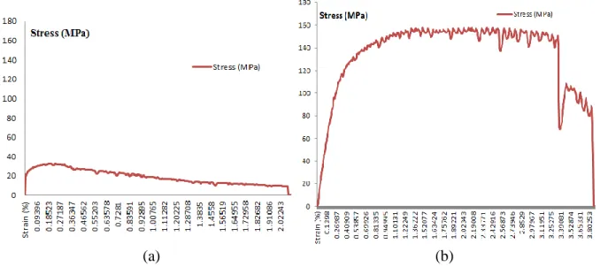
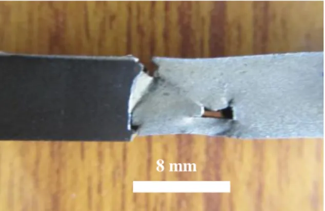
Dog-bone shaped tensile samples of required dimension were prepared by EDM and were tested on MTS. Base metal mild steel and aluminum alloy has got yield strength of 250 MPa and200 MPa and tensile strength of 400 MPa and 320 MPa respectively. Among all the samples of steel advancing side, parameters like, rotation speed - 400 rpm and welding speed - 10 mm/min, has got a maximum tensile strength of 35 MPa only. During the test, sample was suddenly broken (brittle fracture), which shows that the workpieces were not joined properly Fig.11 (a) and (b).
The reason for the brittle-like fracture is that Al and steel were not able to join properly. If there was some diffusion or inter atomic bonding between aluminum and steel, then there would have been much elongation as well as increase in the tensile strength. Out of the 20 samples, sample of above mentioned parameter got at least this much appreciable tensile value (35 MPa).
(a) (b) Figure. 11. Brittle-like fracture observed when steel kept on advancing side
33 On the other hand, when the aluminum was kept on the advancing side and steel on the retreating side; for a particular parameter (300 rpm and 5 mm/min), gave a significant increase in the tensile strength up to a value of 160 MPa (Table 4). Unfortunately we have only one sample of aluminum in advancing side, mainly because we didn’t expect it to be turning out good. May be for another parameter, much higher tensile strength and elongation, could be achieved.
Figure 12 shows the stress-strain graph obtained from the MTS machine, when the test was carried out. As we can observe in the graph in Fig. 12 (a), that there wasn’t much strength and elongation in the joint due to improper diffusion of materials between the welds. Maximum tensile strength of only 35 MPa was able to be achieved. From Fig. 12 (b), i.e. in case of aluminum in the advancing side, we can observe that higher strength of 160 MPa has been achieved. The reason behind is considered to be the proper diffusion of materials in the weld zone, which will be proved microscopically in the Energy Dispersive Spectrometry (EDS) analysis, in the fore coming results.
(a) (b)
Figure. 12. (a) Steel kept in the advancing side (b) Aluminum kept in advancing side
One problem that occurred in aluminum in advancing side is the formation of void (Fig. 13).
Mishra [10] reported that voids generally form on the advancing side and the reason he pointed out was the insufficient forging pressure and high welding speed. If the travel speed is fast, the deformed material will get cooled before the material can fully fill the region directly behind the
34 tool. Also if sufficient heat is not generated, the material will not flow properly and leads to the formation of voids. Though void was formed in this weld, proper diffusion of materials at the interface has finally made it to be the weld provided highest tensile strength. Table 4 shows the welding parameters that were used for the best sample from the steel advancing side sets and aluminum advancing side sample (only one from each). So in this experiment, weld region of aluminum advancing sample, got 70% yield strength and 50% tensile strength of that of the base metal aluminum alloy 6082.
Figure. 13. Formation of void in the advancing side-Al (Al advancing side sample)
Table 4: Welding parameters
Parameters Unit
Steel at advancing side (best sample from the sets)
Aluminum at advancing side (only 1 sample)
Rotation speed Rpm 400 300
Welding speed mm/min 10 5
Yield strength MPa 35 145
Tensile strength MPa 35 160
8 mm
35
3.2 Microhardness distribution
Base metal steel has an average hardness value of 125 HV and that of Al 6082 alloy has a value of 85 HV. It has been noticed that maximum hardness value of steel kept on the advancing side (150 HV) in Fig. 14(a), is comparatively less than the aluminum on the advancing side (260 HV) in Fig. 14(b). Another observation is that a significant difference of hardness is observed at the exact interface, 95 HV in steel advancing side and 250 HV in the aluminum advancing side. This shows that the joint strength was higher for the Al advancing side, thus matching with the earlier tensile strength of the two joints.
(a) (b)
Figure. 14. Microhardness distribution graph (a) Steel in the advancing side (b) Aluminum in the advancing side.
Image of the indenter was captured by the camera at the interface [Fig. 15(a)]. A sudden jump in the hardness value (180 HV) is observed in the aluminum region in Fig. 14(b) is due to the indentation happened on a steel particle found in Al matrix [Fig. 15(b)] in the Al advancing sample. Many blocky steel particles were found spread all over the Al matrix near to the interface, when observed through optical microscope in both the Al advancing and steel advancing samples [Fig. 16 (a)]. Fig. 16 (b) shows the EBSD phase map at the interface in the steel advancing sample to confirm the steel blocky particles in the Al matrix.
36
(a) (b)
Figure. 15. Microhardness indentor image (a) at the interface (b) on a steel particle in the Al matrix (Aluminum advancing side)
(a) (b)
Figure. 16. (a) Optical microscope image showing the numerous steel particles in the Al matrix near to the interface (Aluminum advancing side) (b) EBSD phase map showing the presence of large steel particles in the Al matrix (taken in steel advancing sample)
Hardness distribution of the better sample (Al advancing side) was measured from top to bottom (Fig. 17), of the transverse section and have observed a shift in the peak hardness value towards the base metal steel side very close to the interface. As we measured hardness value for top to bottom peak value got shifted towards the steel base. There is not much difference in the hardness value in the aluminum region. Lowest hardness value was obtained in the heat affected zone of the softer aluminum material.
Aluminum Steel
Steel particles
Aluminum Steel
Steel Aluminum
37 Figure.17. Microhardness distribution from top to bottom of the transverse section in the Al advancing sample
Figure. 18. Orientation Image Mapping (OIM) showingdifferent grain size along with micro- hardness graph at different regionsacross the cross-section perpendicular to the weld direction in the steel advancing sample
Al Fe
38 Fig. 18, shows the Orientation Image Mapping (OIM) analysis taken along the crossectional area perpendicular to the weld direction after electropolishing. Using Electron Back Scattered Diffraction (EBSD) in Scannig Electro Microscopy (SEM) at IIT Bombay, three scans were taken at three different regions – (a) Aluminum base side (b) Stir (Nugget) zone and (c) Steel base side for finding out the grain size. It was clearly observed that grain size in the stir zone was smaller due to the severe plastic deformation of the material by the tool deformation as compared to the normal base aluminum and steel side.At the interface, Al was higly deformed and grain reduction taken place much higher than from the steel region, because of the travelling of tool pin via the aluminum side.
3.3 Energy Dispersive Spectrometry (EDS) analysis of the joint interface
EDS point analysis of aluminum advancing sample, was firstly taken in the steel region much away from the interface, which projected only Fe component [Fig. 19(a) and (b)]. But, when the analysis was taken much more near to the interface in the steel region itself, small Al component was observed, which shows that little Al has come over to steel side [Fig. 19(c) and (d)]. EDS when taken very close to the interface in the steel side, Al component was observed more than the Fe component [Fig. 19(e)], that shows the homogeneous distribution of Al into the steel region. Interesting fact is that, when EDS scan was taken on the Al region [Fig. 19(f)] very close to the interface, Fe component was totally absent which means that steel has not mixed homogeneously into Al side. This is contradictory to the optical microscope image data that shown that bulky steel particles moved into aluminum matrix. On the basis of this analysis we can confirm that, though steel particles moved macroscopically into the aluminum region, microscopically it has not diffused into aluminum. But we can clearly see that Al has moved microscopically i.e. homogeneously diffused into the steel region, that accounted for the appreciable high tensile strength of the weld region for the aluminum advancing sample.
39 (a) (b)
(c) (d)
Fe
Al Al
Fe
Al
Fe
Al
Fe
40 (e) (f)
Figure. 19. (a) & (b) shows the EDS analysis taken in steel region little far from the interface in the aluminum advancing side sample and only Fe component was seen; (c) & (d) also shows the EDS analysis taken in the steel region much closer to the interface, here Fe and small amount of Al was seen; (e) very close to interface, Al component has raised higher than Fe component; (f) analysis taken in Al region very close to interface but there was no evident of Fe component.
Final interpretation of joining of aluminum and steel in FSW
The adequate plunge depth and the tilt angle provided at the back (rear) side of the moving tool assists in forging of the material from the retreating side to the advancing side at the trailing edge (back side) of the tool. Irrespective of the position of aluminum in the advancing or retreating side, tool plunges into it and makes it soften easily. Problem is only with the deformation and softening of the harder steel. When steel is on the advancing side, instead of steel, aluminum on the retreating side gets softened and deformed further, and try to get forged into the un-deformed and un-softened steel across the weld line, which leads to poor diffusion of Al and steel. On the contrary, when steel is on the retreating side, it gets sufficient forging pressure at the back side of the tool, which makes the steel to deform and soften nicely and move across the weld line, where the already softened aluminum will get homogeneously diffused in to the steel that eventually leads into improved mechanical properties of the joint.
Al
Fe
Al
Fe
41
Chapter 4
Conclusion and Scope for future work
FSW is an innovative solid state welding technology, if used sensibly have the ability to join similar and dissimilar materials (soft as well as hard), that are widely applicable to various industrial purposes. In dissimilar material joining, offset of the tool with respect to the workpiece and the significance of placing the hard and soft material in the advancing or retreating side of the weld, are as highly significant as that of other welding parameters like tool rotation speed (rpm) and welding speed (mm/min). Here, soft aluminum when kept on the advancing side has provided a drastic increase in the mechanical properties like hardness, tensile and yield strength of the welded joint. The reason for this, were tried to figure it out microstructurally by EDS analysis and it was clear that the hot and soft aluminum if moves homogeneously into heated steel region, proper joining will takes place and the weld will be having good mechanical properties. On the contrary, when the steel was kept on the advancing side, only some blocky steel particles went into Al, and Al was not able to diffuse homogeneously into unsoften steel region at the interface, that eventually lead to poor joint strength. Overall we can conclude that Al when kept on the advancing side was able to homogeneously diffuse into the steel region at the interface because of the sufficient forging pressure applied by the tool upon the steel on the retreating side, thereby giving the weld a higher strength and hardness.
So it was able to find out there is a marked difference in the strength when a hard material was kept on the retreating side rather than on the advancing side in dissimilar FSW. Here in this case, maximum tensile strength was obtained for one particular welding parameter in steel retreating sample, and now the scope for future work is that whether there is a possibility of further increase in other mechanical properties of the joint by changing different welding parameters.
Developing a generalized mathematical model by Linear Programming Problem (LPP) for optimizing the parameters of the weld can be of another study. This mathematical expression can
42 be again optimized for getting maximum tensile strength of the joint. With this optimized and generalized mathematical model one can easily find out the best parameters for different working conditions (for e.g. if there is a change in the thickness of the weld). Before the start of welding itself it will be able to know the approximate tensile strength the sample can achieve with so and so parameters.
Also one can carry out a research by plunging a harder tool like Tungsten-20 %Carbide (W-C) in the steel side first and then slightly offsetting the tool into aluminum region to find out proper welding. For all these studies a sophisticated FSW machine is highly essential in which the tool can be moved in all the 3-D directions (X, Y and Z) automatically, with the help of a computer control. Once a proper weld of good strength is obtained, even one can carry out a study in the evolution of any particular microtexture and can find out whether there is any special correlation with texture and mechanical properties in friction stir welding of dissimilar materials.
43
References
[1] Solid State Welding: Key to metals Articles; www.keytometals.com/Article51.htm
[2] W.M. Thomas, E.D. Nicholas, J.C. Needham, M.G. Murch, P. Templesmith, C.J. Dawes, G.B. Patent Application No. 9125978.8 (December 1991)
[3] Rajiv S. Mishra, Z.Y. Ma. “Friction stir welding and processing”. Materials Science and Engineering (2005); R 50: 1–78
[4] Z.Y. Ma, A.L. Pilchak, M.C. Juhas and J.C. Williams. “Microstructural refinement and property enhancement of cast light alloys via friction stir processing”. Scripta Materialia (2008); 58: 361-366
[5] Yong X. Gan, Daniel Solomon and Michael Reinbolt. “Friction Stir Processing of Particle Reinforced Composite Materials”. Materials (2010); 3: 329-350
[6] Z. Feng, M. L. Santella, and S. A. David “Friction Stir Spot Welding of Advanced High- Strength Steels – A Feasibility Study” SAE International (2005)
[7] P L Threadgill. “A review of friction stir welding: Part 2, selection of tool materials”. The Welding Institute (TWI); February 2003
[8] P L Threadgill and M E Nunn. “A review of friction stir welding: Part 1, process review”.
The Welding Institute (TWI); February 2003
[9] Douglas Burkes, Pavel Medvedev, Michael Chapple1, Amit Amritkar, Peter Wells, Indrajit Charit. “The role of Friction stir welding in nuclear fuel plate fabrication”. Idaho National Laboratory (USA), University of Utah (USA), University of Idaho (Moscow); TMS 2009 Annual meeting
[10] Rajiv S. Mishra. Murray W. Mahoney. “Friction Stir Welding and Processing”. ASM International; 2007: page 14 of 352
[11] K. Kumar, Satish V. Kailas. “The role of friction stir welding tool on material flow and weld formation”. Materials Science and Engineering (2008); A 485: 367-374
[12] G. Buffa, J. Hua, R.Shivpuri, L. Fratini. Mater. Sci. Eng. (2006); A419: 381-388 [13] N. T. Kumbhar and K. Bhanumurthy. “Friction Stir Welding of Al 6061Alloy”. Asian J.Exp.Sci. (2008); Vol. 22, No. 2: 63-74