This thesis aims to address some of the major challenges in GPU-based acceleration of structural topology optimization discretized by 3D unstructured meshes. For the same reason, structured meshes have been used by the majority of the studies in the literature dedicated to GPU-based acceleration of structural topology optimization.
Motivation
Running matrix-free FEA solver using unstructured meshes on a GPU requires a large amount of CPU to GPU data transfer, and a large number of global memory read operations. The thesis later focuses on improving the computational performance of GPU-based matrix-free FEA solver by tackling the challenges posed by unstructured meshes on GPU.
Objectives of the Thesis
Organization of Thesis
In the density-based topology optimization method, an 'artificial' density variable 'ρe' is introduced at each mesh element. An example of this is the 'sequence method', where the initial optimization iteration uses p = 1 and the number gradually increases in subsequent iterations [56].
SIMP-based Topology Optimization
V(ρ) is the final volume of the structure, and Vd is the volume of the original design domain. Then, compliance sensitivity is calculated with respect to the design variables [50] as given in Equation (2.5).
Conjugate Gradient Solver and Preconditioning
A detailed explanation of the method can be found in Hestenes and Stiefel [60] and Nocedal and Wright [62]. In addition, if the problem is ill-conditioned, it can also degrade the convergence speed of the CG method [64].
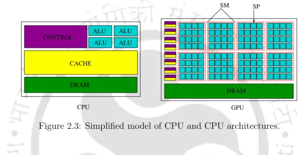
GPU Computing
However, the rate of convergence of the iterative solver may depend on the size of the subdomains, the number of subdomains, and the overlap between them [71]. The diagonal preconditioner is chosen because it is computationally efficient and easy to implement, as it requires only the diagonal elements of the matrix to be calculated and stored. This makes it particularly attractive for problems with a large number of unknowns, since the computational cost of the preconditioner is proportional to the size of the matrix [67].
Programs can only control the size of the grid and blocks, while the GPU handles the creation of warps. Global memory is the largest in size and available to the entire thread throughout the program's runtime. The GPU architecture is designed in such a way that all the threads in a warp execute the same instruction.
Literature Review
- Parallel Computing for SIMP-based Topology Optimization
- GPU Acceleration of SIMP-based Topology Optimization
- Using Structured Mesh
- Using Unstructured Mesh
- GPU Acceleration of Other Topology Optimization Methods
- Open-Source Parallel Topology Optimization Frameworks
- Closure
- Proposed Element-by-Element SpMV Strategy ‘ebe’
- Proposed Node-by-Node SpMV Strategy ‘nbn’
- Proposed Customized Nodal Connectivity Storage For-
- Algorithm for ‘nbn’ Strategy
44] used a shared memory system to accelerate topology optimization of 2D continuum structures based on the OC method. Multiple GPUs were used to accelerate FEA, sensitivity analysis, and topology optimization mesh filtering. Challis et al.
86] presented a fully parallel implementation of the parameterized array level method for large-scale structural topology optimization. GPU was used by Suresh [47] to accelerate topology optimization based on the topology sensitivity method. Matrix-free iterative solvers are an ideal choice for accelerating GPE-based topology optimization due to their inherent parallelism [55].
Topology Optimization using Proposed FEA Solver
The proposed nbn strategy is shown in Algorithm 3 which starts by assigning a global index to a compute thread representing a node in the mesh. The element density of element 'e' is read from ρ and penalized using SIMP parameter 'p' in line 7. Finally, the matrix vector multiplication between Ke and ue is performed in line 11 and the result is stored in the variable val .
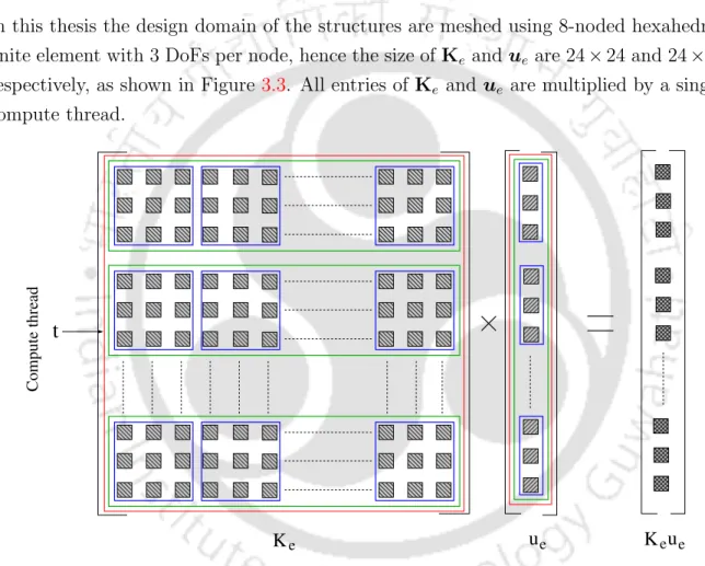
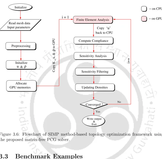
The expression in line 11 is an implicit representation for the calculation of all three DoFs of a node. The meshing is performed using the Ansys R16.1 APDL module with 8-node hexagonal elements for all examples in the thesis. The next stage is data pre-processing, which includes calculation of Ke for all finite elements in the mesh, preparation of the adjacent element list for the mesh independence filter, etc.
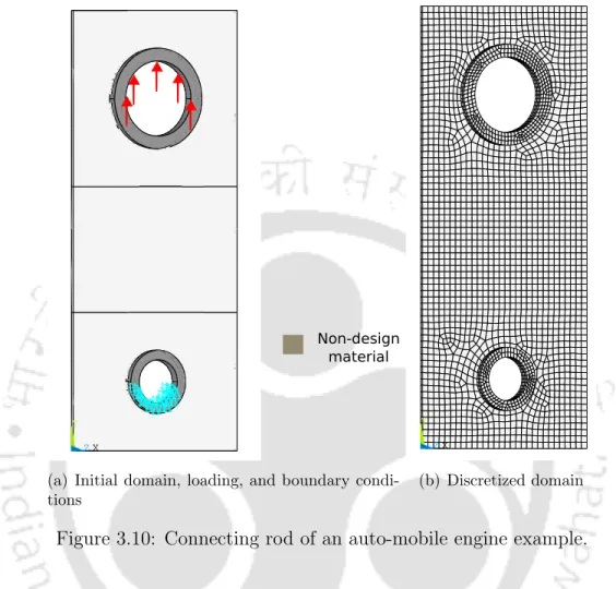
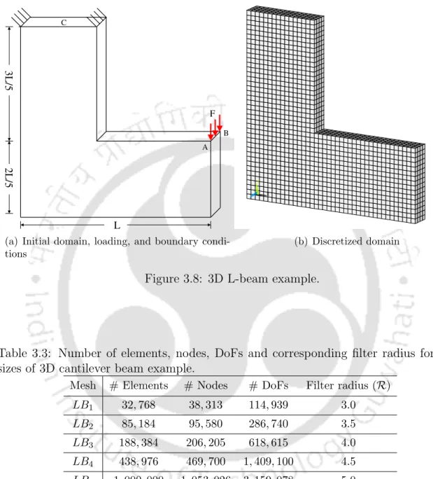
Benchmark Examples
Michell Cantilever
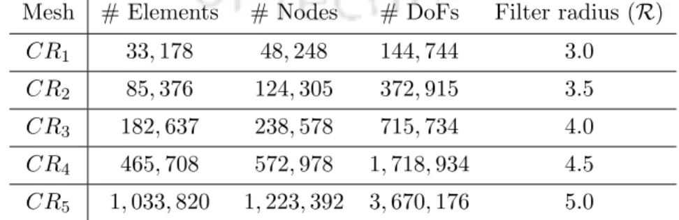
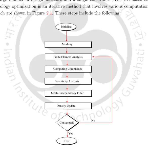
The supported semicircular boundary is subject to the Dirichlet boundary condition, while the charged points in Figure 3.9(a) are subject to Neumann. a) Initial domain, loading and boundary conditions. The five mesh sizes used for this example are listed in Table 3.4. a) Initial domain, loading and boundary conditions.
Connecting Rod of an Auto-mobile Engine
Results and Discussion
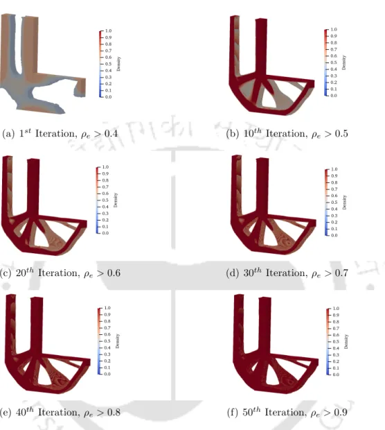
Optimal Topology
Computational Performance
On the right axes of the plots, the speeds are shown and it can be seen that for all network sizes, the ebe strategy achieves a higher speed than the nbn strategy. SpMV on the GPU requires the Ke of all elements stored in the GPU's global memory. These factors contribute to the inferior performance of the nbn strategy compared to the ebe strategy.
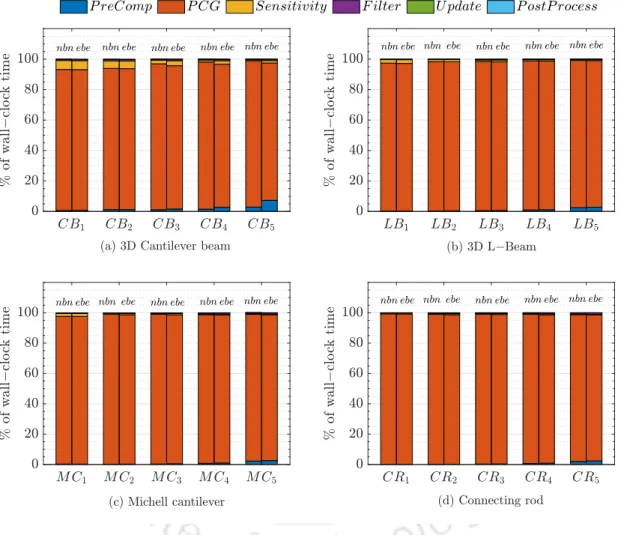
Next, the execution time of the various computational steps of the GPU-based topology optimization framework shown in Figure 3.6 is analyzed. Depending on the mesh size, the %W C value for the ebe strategy ranges from 92% to 95% of the total wall clock time. Analysis of the results from Figure 3.16 reveals that even when FEA is performed on the GPU, the computational bottleneck of the topology optimization framework remains.
Closure
In line 2, a vector 'Cs' is allocated in shared memory to store the elementary data of the connection. Each thread allocated an element 'e' copies an entry from C to a vector Cs in line 5. The mat-vec operation is performed in line 14 and the result is stored in the variable.
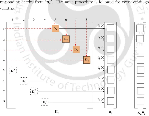
The row index of Ke, assigned to this thread, is shown in line 9. Finally, in line 15, the thread calculates Ke×ue, and the penalized density (ρe) is multiplied by the product. Mat-vec operation in line 15 represents multiplication for the entries within the inner blue boxes in Figure 4.3.
Computational Performance
Closure
Accessing the elementary stiffness matrices still requires a large number of global memory read operations. The computational performance of the proposed matrix-free PCG solver can be further improved by reducing the amount of CPU-GPU data transfer and optimizing the data access on the GPU. The proposed matrix-free PCG solver for topology optimization requires that the basic stiffness matrices for all finite elements be explicitly calculated and stored.
The final objective of the thesis is to develop efficient data storage and data access models on the GPU to further improve the performance of the proposed matrix-free PCG solution for topology optimization. Using this feature, SpMV can be performed using only the symmetric half of the elemental stiffness matrices which can significantly reduce the amount of data copied to the GPU. We develop a new GPU strategy 'ebeSym' which performs SpMV of the proposed matrix-free PCG solution.
Customized Data Storage Format
Storage Format for Diagonal Sub-Matrices
The storage model used to store the entries of the diagonal sub-matrices in the vector κd is shown in Figure 5.2. At the top of the figure, all diagonal sub-matrices of an elemental stiffness matrix are shown with their entries. The vector κd is created by storing the entries of the first element (E1) followed by other elements (E2,.
Storage Format for Off-Diagonal Sub-Matrices
Using Kaand's symmetry properties, the data storage patterns discussed in Section 5.2.1 and Section 5.2.2 develop a symmetry-based SpMV strategy, which is discussed in the following section.
Proposed Symmetry-based SpMV Strategy ‘ebeSym’
The eight threads first multiply the entries of the diagonal array "Xi" by the corresponding entries of the vector "ue". Instead of reading the same sub-array twice from global memory, a stream operation is used and the sub-array is read by two threads at the same time. Next, the 'global dof' index is read from the connection matrix, which represents the location in the output vector for writing the results with 't' thread.
The index 'idx1' is the multiplication position in 'κd', while the index 'idx2' is the multiplication position in 's u'. Finally, lines 18 - 20 write the results of the multiplication into the output vector 'r' for all three DoFs. Exploiting the symmetry property of elementary matrices for SpMV operation is an idea that already exists in the literature.
Computational Performance
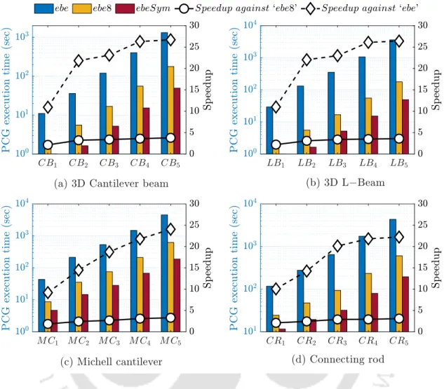
The speedup obtained by the ebeSym strategy compared to the ebe and ebe8 strategies is shown on the right Y-axis of the same graphs. It can be observed that the ebeSym strategy takes much less time than the ebe and ebe8 strategies for all mesh sizes of the four benchmark problems. In the same graph, the % wall clock time of different computational steps corresponding to the symmetry-based ebeSym strategy is compared to the 8-thread-per-element 'ebe8' strategy using full Ke.
From Figure 5.6 it can be observed that theebeSymstrategy's 'P CG' step requires between 67% and 97% of wall clock time even when performed on the GPU. The 'Sensitivity' step then consumes between 1% and 5% of the wall clock time which is much less compared to the previous steps. It can be seen that for the smallest mesh sizes of the four examples, both strategies require almost similar amounts of memory.
Closure
In this thesis, an efficient GPU-based matrix-free FEA solver is developed for topology optimization of large-scale 3D continuum structures, discretized using unstructured meshes. With the aim of accelerating the topology optimization, the entire FEA solver is executed on the GPU. Through a literature survey and through initial analysis, the computational bottleneck of the FEA solver is identified.
The combination of these new GPU computing strategies accelerated the performance of the proposed FEA solution by many times. The wall clock time comparison of computational steps concludes that the FEA solver is the computational bottleneck of the topology optimization framework. The GPU-based matrix-free FEA solver proposed in this thesis performed efficiently on benchmark problems taken from the literature.
Future Work
Overall, the work presented in this thesis makes an important contribution to the research domain of GPU-based acceleration of structural topology optimization using large 3D unstructured meshes. An overview of additive manufacturing and topology optimization processes for weight reduction studies in various industrial applications. In Martin Philip Bendsøe, Niels Olhoff and Ole Sigmund, editors, IUTAM Symposium on Topological Design Optimization of Structures, Machines and Materials, pages 207–215, Dordrecht, 2006.
Topology optimization for simultaneous design of structures with multi-patch microstructures per level series. Topology optimization using PETSc: an easy-to-use, fully parallel open source topology optimization framework.
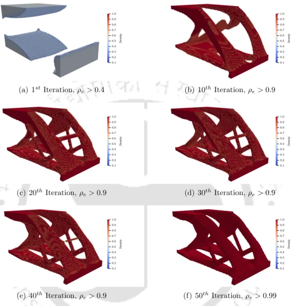
Computational steps of SIMP-based structural topology optimization
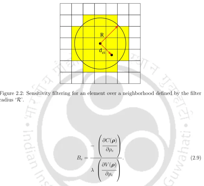
Sensitivity filtering for an element over a neighborhood defined by the
Simplified model of CPU and CPU architectures
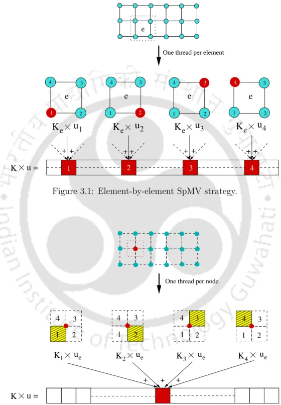
Element-by-element SpMV strategy
Node-by-node SpMV strategy
Matrix-vector multiplication by the proposed GPU-based element-by-element
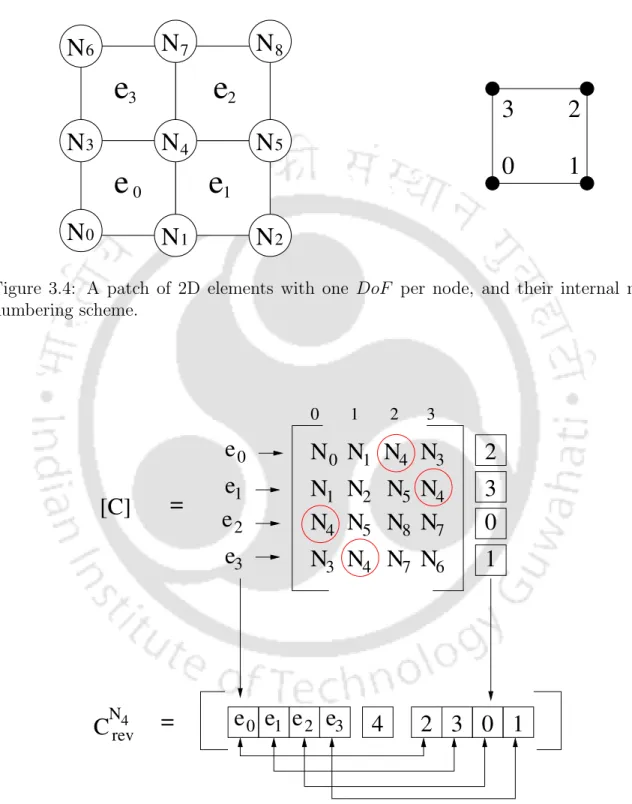
A patch of 2D elements with one DoF per node, and their internal node
Customized nodal connectivity storage format ‘C rev ’
Flowchart of SIMP method-based topology optimization framework using
Michell cantilever example
Connecting rod of an auto-mobile engine example