An overview of the physical shared and control channels of the UMTS Long Term Evolution (LTE) system can be found in [1,2]. However, the performance of these channel estimation methods strongly depends on the signal-to-noise ratio (SNR) and the number of allocated subcarriers, or equivalently, resource blocks (RBs) in the uplink.
Radio Channel Propagation
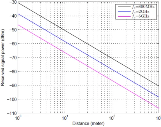
Large-Scale Fading
The average path loss model in equation (2.3) is an average of the path loss at different locations for a given given. For the path loss model used in the 3GPP spatial channel model (SCM), v= 10dB in the urban microscenario [6].
Small-Scale Fading
In a Rayleigh fading channel, the CDF of the received signal power is described by the CDF of a central chi-square distribution [7], i.e. due to the existence of the dominant component, the CDF of the received signal power in a Rician fading channel is described. channel is described by the CDF of a non-central chi-square distribution [7], i.e.
Abbreviations
Frame Structure
Frame Structure Type 1
LTE defines two different CP lengths: a Normal CP and an Extended CP, corresponding to seven and six OFDM/SCFDMA symbols per slot, respectively. In half-duplex FDD operation, the UE cannot transmit and receive at the same time, while there are no such restrictions in full-duplex FDD.
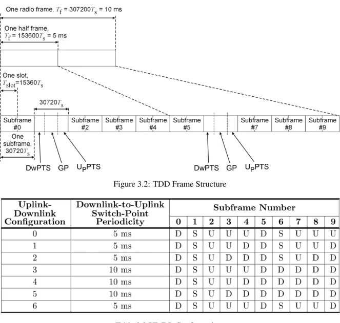
Frame Structure Type 2
Slot Structure and Physical Resources for Uplink
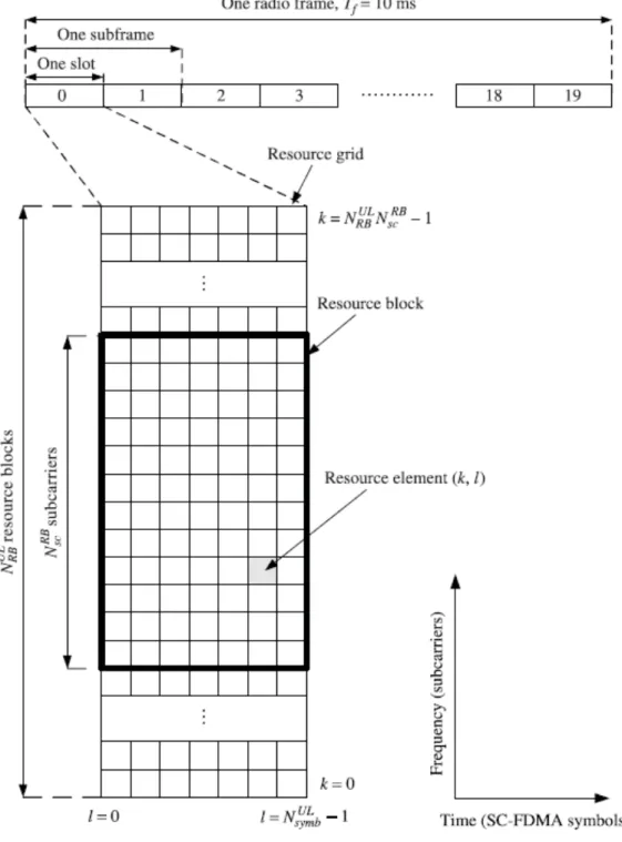
Resource Grid
For FDD, uplink and downlink transmissions are separated in the frequency domain, each with 10 subframes. The number of SC-FDMA symbols in a slot depends on the CPLength configured by the higher layer parameter UL-Cyclic Prefix Lengthand is given in the following table.
Resource Elements
Resource Blocks
The relationship between the physical resource block number PRB in the frequency domain and the resource elements (k, l) in a slot is given by.
Simulation Parameters
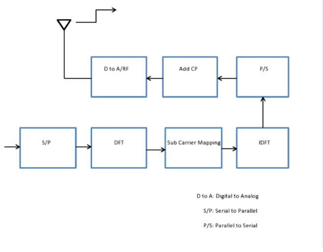
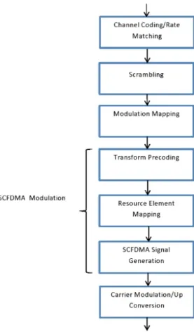
Uplink (UL) Physical Channel Processing involves the transfer of blocks of bits originating from the channel encoder or Rate Matching to the antenna ports. The baseband signal representing the physical shared uplink channel is defined in terms of the operations shown in Figure 4.1a. The output symbols of the modulation mapping operation correspond to the input signal of Figure 4.1a.
In PUSCH, the DFT precoding size corresponds to the number of scheduled subcarriers used for PUSCH transmission in the SC-FDMA symbol, MPUSCHsc. In general, encoding the encoded data helps ensure that receiver-side decoding can take full advantage of the processing. By using different coding sequences for different mobile terminals, the interfering signal(s) are randomized after decoding, ensuring full use of the processing gain provided by the channel code.
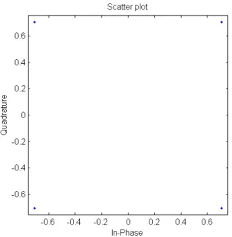
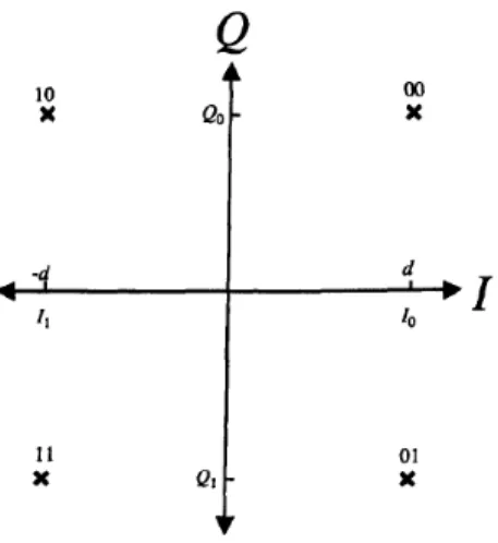
Modulation Mapper
QPSK
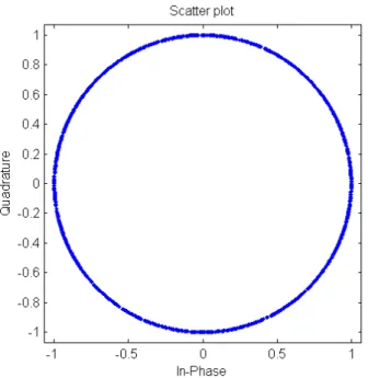
Transform Precoder
Uplink Reference Signals
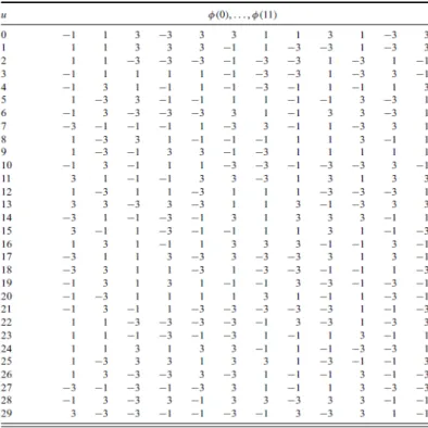
Uplink Reference Signal Sequences
For sequence lengths up to five source blocks, i.e.MscRS =mNscRB, 1≤m ≤5each sequence group contains a single base sequence (v = 0). We know that for sequence lengths up to five source blocks, i.e. MscRS = 60, each sequence group contains a single base sequence (v = 0). To randomize the interference between cells, sequence group hopping can be enabled by higher layers.
The group hopping pattern fgh(ns) is the same for PUSCH and PUCCH and is given by fgh(ns) = 0 if group hopping is disabled. For reference signals of length MscRS ≤ 5NscRB, the base sequence number within the base sequence group is given by v= 0. In other cases, when sequence hopping is not enabled or group hopping is enabled, the base sequence number within the base sequence group in the slot is always set to zero, that is, v = 0.
Demodulation Reference signals
A total of 504 jump patterns can be obtained through 17 group jump patterns and 30 sequence shift patterns. The value of n(2)DM RS is signaled in the UL scheduling assignment and is given in Table 4.4(c). The demodulation reference signal sequence for PUSCHrP U SCH() is multiplied by the amplitude scaling factor βP U SCH and mapped in sequence starting merP U SCH(0) to the same set of physical resource blocks for the corresponding PUSCH transmission.
Resource Element Mapping
SC-FDMA Signal Generation
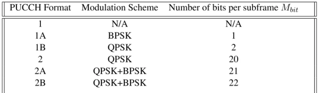
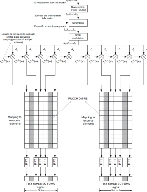
The combination of uplink control information formats supported on PUCCH include hybrid ARQ ACK/NACK using PUCCH format 1A or 1B, Channel Quality Indicator(CQI)/Precoding Matrix Indicator(PMI) using PUCCH format2, CQI/PMI and hybrid ARQ ACK/NACK uses PUCCH format 2A or 2B for the normal cyclic prefix or format 2 for extended cyclic prefix[2]. The formats 1A and 1B are used for standalone transmission of single-bit and two-bit ACK/NACK respectively. The format 2 is used when CQI/PMI is transmitted with our ACK/NACK multiplexing using a (20,A) code or when CQI/PMI and ACK/NACK are coded together for the case of extended cyclic prefix[ 1].
The modulation for one-bit ACK/NACK is BPSK while QPSK is used in all other cases. For PUCCH formats 2A and 2B, bits b(20), .., b(Mbit -1) representing one or two ACK/NACK bits are modulated similarly to ACK/NACK in formats 1A and 1B as described in the table 5.2. This modified reference signal carrying ACK/NACK is then mapped to the SC-FDMA symbol originally carrying the second reference signal within the slot, as shown in Figure 5.1.
PUCCH Mapping
A mapping of PUCCH format 2 in a slot is shown in Figure 5.1 for the example of a conventional cyclic prefix. In the case of an extended cyclic prefix, the second reference signal within the slot is dropped so that five SC-FDMA symbols are available for the PUCCH. This results in one modulation symbol d(10) used to generate the reference signal for PUCCH 2A and 2B formats.
Within the physical source block used for transmission, the mapping from z(i) to source elements (k,l) not used for transmission of reference signals takes place in ascending order of first k, then l and finally the slot number, starting with the first slot in the subframe. The sources used for the transmission of PUCCH formats 2/2A/2B are identified by a source index n(2)P U CCH from which the cyclic offset is determined. The physical resource block to be used for the transmission of PUCCH in slotn is given by: nP RB =bm.
Demodulation Reference Signal
- Least Square Estimation
- LMMSE Channel Estimator
- DFT Based Channel Estimation with transform domain cutoff filter
- Linear Averaging Method
To recover the transmitted bits, the channel power must be estimated and compensated in the receiver. In the LTE uplink, a block of pilot symbols is transmitted periodically to estimate the channel. Each slot consists of 7 transmission blocks, and the pilot block is located in the center of the slot [3].
By exploiting a prior knowledge of the channel statistics, the LMMSE estimator is optimal in the sense of minimizing the MSE of the channel estimate and thus provides the best channel estimation performance in terms of the lowest MSE. DFT-based channel estimation is based on the property that the energy of the channel is highly concentrated in the time domain. So the final channel estimates in the frequency domain with transform domain cutoff filter and in band noise removal can be obtained as.
Equalization
ZF Equalization
MMSE-LE Without Co-variance Estimation
MMSE-LE With Co-variance Estimation
Inverse Precoding
Demodulation Section
- Soft Demodulation of Binary Modulation in an AWGN Environment
- Soft Demodulation in Rayleigh Fading Environment
- BER vs SNR Plots for MMSE-LE with and without Co-variance Estimation
- LS Estimation
- LMMSE Estimation
- DFT Based Channel Estimation
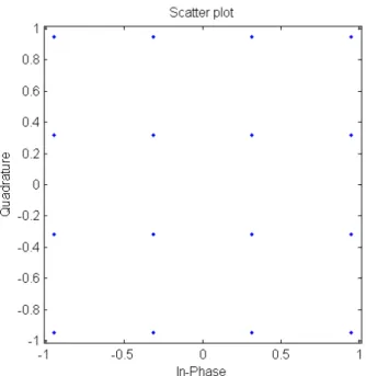
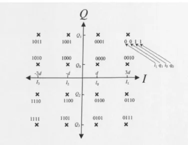
Therefore, 16-QAM modulation is implied in the following description and in the sections regarding the approximation methods. The SR requirement of UE is only given by energy emissions in the control area in the resource grid. In the case of codeword format 2a/2b, one or two bits of HARQ-ACK information is added to format 2 only.
After adding a cyclic prefix (CP), the signal in the time domain enters the transmission channel. Consider the LS solution given in equation (7.2), it can be written in vector form. Thus, the final estimates of the channel in the frequency domain with the cutoff filter of the transform domain and in the removal of band noise can be obtained as section (6.1.3).
Interpolation
Channel estimates of all resource elements H(mi, nk)i=1,..7 and k=1,..12 are found using channel statistics Yp,Xp. To obtain the cross-correlation and autocorrelation coefficients between pilot locations and non-pilot locations, we assume a constant PDP and a constant Doppler spectrum of the channel.
Equalization
ZF Equalization
MMSE Equalization
Demodulation
Soft Demodulation of Binary Modulation in an AWGN Environment
Now suppose that a transmitter transmits a modulated signal through the AWGN channel which has zero mean and noise variance of σ2. Denotes the received signal asr=rI+rQ=x+n, LLR of the received soft-bit from the real (or in-phase) component rI[5]. From this equation, it is clear that the LLR of a binary or double-binary modulation scheme is just a simple function of the real or imaginary part of the received signal and its noise variance.
Soft Demodulation in Rayleigh Fading Environment
Continuing the derivation and assuming that the noise ternhˆ†nof is Gaussian distributed, it can be demonstrated. The constellation representations of 16 QAM adopt {ilqli0q0}bit arrangement, where letters indicate that bits originate from the I-axis, this constellation point consists afil= 0,i0 = 1bit from I-axis and ql= 0,q0 = 1bit from Q-axis. 2σ2kαˆk2(zy− kαˆ k2y)2 (7.42) Due to the simplicity of the exact soft demodulation method for the QPSK case, no approximation is needed.
Block Error Plots for PUCCH
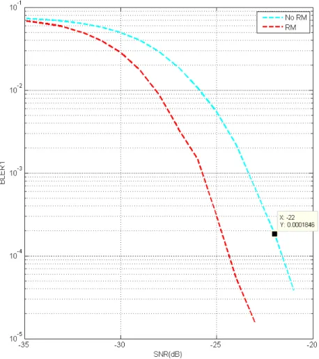
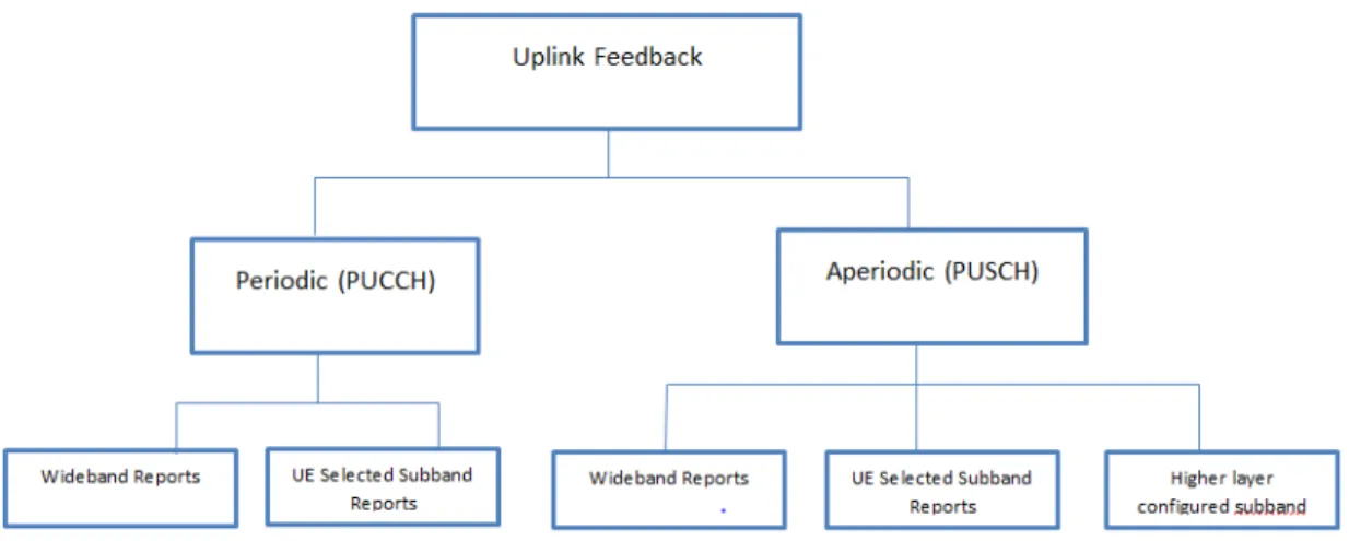
The periodic reporting of Channel Quality Indicator(CQI), Precoding Matrix Indicator(PMI) and Rank Indicator(RI) is performed using PUCCH, while aperiodic is performed on the PUSCH data channel is shown in Figure 8.1. Three forms of channel coding are used for periodic reporting on PUCCH, one for CQI/PMI, another for hybrid ARQ ACK/NACK and scheduling request, and finally one for a combination of CQI/PMI and hybrid ARQ ACK/NACK[2]. CQI/PMI bits input to the channel coding block are denoted by a1, a1, ..aA, where A is the number of bits and depends on the transmission format.
These bits are encoded using a variable Reed-Muller(RM) (20,A)[1,3] code whose code words are linear combinations of the 13 basic sequences denoted by Mi,na, given in Table 8.1.
Channel Coding for Aperiodic Reporting
Decoding algorithm for APeriodic report-Long CQI
Decoding algorithm for Aperiodic report -Short CQI
When the number of bits in each encoding block is less than seven, there is no mask sequence bending for the codeword. Interleaving and bipolar transformation process is only required for the received word while not for the mask matrix.
Decoding algorithm for Periodic report-CQI
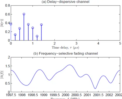
Find the element in the word with the largest magnitude for the FHT and then decode them based on the column number and its sign. The name OFDM comes from the fact that the frequency responses of the subchannels overlap and are orthogonal. Each subcarrier is modulated with a data symbol, and an OFDM symbol is formed by simply adding the modulated subcarrier signals.
The orthogonality of OFDM subcarriers can be lost when the signal passes through a time-dispersive radio channel due to inter-OFDM symbol interference. In cyclic prefix expansion, the last part of the OFDM signal is added as a cyclic prefix (CP) at the beginning of the OFDM signal, as illustrated in figure. The cyclic prefix length is generally chosen to accommodate the maximum delay spread of the wireless channel. The addition of the cyclic prefix makes the transmitted OFDM signal periodic and helps avoid inter-OFDM symbol and inter-subcarrier interference.