Introduction 1
Background 2
Radar signal processing is defined as the manipulation of the received signal, represented in digital format, to extract the desired information while rejecting unwanted signals. Pulse compression allowed the use of long waveforms to obtain high energy at the same time to achieve resolution of a short pulse with internal modulation of the long pulse. Resolution is the ability of the radar to distinguish targets that are located close together in both range and bearing.
The internal modulation can be binary phase coding, polyphase coding, frequency modulation and frequency stepping. These include reduction of peak power, relevant reduction of high voltages in radar transmitter, protection against detection by radar detectors, significant improvement of distance resolution, relevant reduction in clutter problems and protection against disturbance of spread spectrum action [1.3]. In pulse compression technique, the transmitted signal is frequency or phase modulated (but not amplitude modulated) and the received signal is processed in the receiver, in a specific filter called "matched filter".
Barker code is the binary phase coded sequence of 0, π values resulting in equal sidelobes after passing through the matched filter. 1.7] proposed an RBFN for pulse compression that produced high SSRs in various adverse situations of noise, with clock misalignment.
Motivation 3
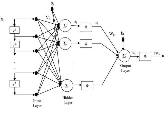
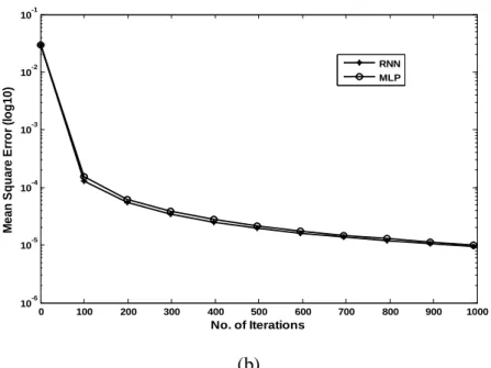
The structure of MLP for three layers is shown in Figure 3.2. The three layers are input, hidden and output layers. The input vector is propagated through a weight layer V. The output of jth hidden node is given by, . is the input value at the node. is the bias for j hidden node, and is the activation function. The response of the network is provided by the output layer which is linear in nature.
According to Micchelli [4.8], the element of the interpolation matrix φ which is non-singular is given by , where denotes the Euclidean norm. A dynamic RRBF is applied for color image restoration, which uses a hybrid of two algebraic networks, namely a radial basis function and an MLP network [4.14]. RBFN effectively suppresses noise while preserving image detail. The modification is done for the code p2 and the modified code q in terms of p2 is expressed as. 5.7) The autocorrelations of the original code p2 and the modified code q are related as follows.
Code P2 has N2 elements and the phase of the ith element of array j is shown as. 5.14) Where i and j are integers ranging from 1 to N. The value of N must be equal in order to obtain sidelobes with low autocorrelation. Hardier, "RBF Recurrent Networks for Suspension System Modeling and Damper Wear Diagnosis," IEEE 1998 International Joint International Conference on Neural Networks Proceedings, vol.
Thesis layout 3
Adaptive Filtering Techniques for Pulse Radar Detection 5
Introduction 6
The reflected energy sent back to the radar not only indicates the presence of the target, but by comparing the received echo signal with the transmitted signal, its location can be determined along with other target-related information. Part of the transmitted signal is received by a reflecting object (target) and re-emitted in all directions. It is the energy re-radiated backward that is of primary concern to the radar.
The receiving antenna collects the returned energy and delivers it to a receiver, where it is processed to detect the presence of the target and extract its location and relative velocity. The distance to the target is determined by measuring the time it takes for the radar signal to travel to the target and back. Short pulses are better for range resolution, but conflict with energy, long range detection, carrier frequency and SNR.
At the transmitter, the signal is relatively small in amplitude to make it easier to generate, and large in time to provide enough energy in the signal, as shown in Figure 2.1. At the receiver, the signal has a very high detectable amplitude and is small in time [2,5].
Pulse Compression 7
- Phase Coded Pulse Compression 8
- Barker Codes 8
In this technique, a form of phase modulation is placed on the long pulse which increases its bandwidth. In this form of pulse compression, a long pulse of duration T is divided into N sub-pulses each of width τ as shown in Figure 2.2. The output of the matched filter will be a peak of width τ with an amplitude N times greater than that of long pulse.
The output waveform extends a distance T to either side of the peak response or central peak. The portions of the output waveform other than the peak are called time sidelobes. A criterion for selecting a good "arbitrary" phase-coded waveform is that the autocorrelation function should have equal-time sidelobes [2.1].
A binary phase coded sequence of 0, π values that results in identical sidelobes after passing through a matched filter is called a Barker code. There are six identical temporal sidelobes on either side of the peak, each marked 22.3 dB below the peak.
Matched Filter 9
The output of the matched filter receiver is the cross-correlation between the received waveform and the replica of the transmitted waveform.
Adaptive Filtering Techniques 10
- Modified RLS Algorithm 13
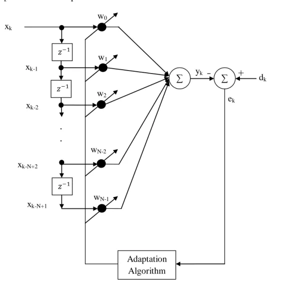
The weights are updated for each iteration until the estimate of the gradient is minimized. The signal bandwidth is obtained by modulating phase or frequency of the signal, while maintaining constant pulse amplitude. An artificial neuron basically consists of a computing element that performs the weighted sum of the input signal and the connection weight.
3.9) The output of the MLP network is determined by a set of output weights, W, and is calculated as, . The Doppler sensitivity is caused by shifting the phase of individual elements in the phase code. The Doppler sensitivity is caused by phase shift of the individual elements of the input phase code.
A length–8 Golay pair and its complementary property are illustrated in Figure 5.1. a, b) Golay complementary codes (b, c) their respective autocorrelation functions (e) sum of the autocorrelations. The phase of the ith code element in the jth row of code group is calculated as. From the above figure it is clear that the Frank code has the largest phase increments from sample to sample in the middle of the code.
Therefore, when the code is passed through a bandpass amplifier to a radar receiver, the code is attenuated more in the center of the waveform. The sub-Doppler correlation fd is obtained by correlating the transmitted with the received multiplied by , where T is the code length. The codes P1, P2, P3, P4 are obtained from modified versions of the Frank code, with the dc frequency term in the middle of the pulse rather than at the beginning.
Code P1 has N2 elements and the phase of the ith element of the jth group is represented as. The P1 code has the largest sample-to-sample phase increments at both ends of the code. An important advantage of the P1 and P2 codes over the Frank code is that they are more tolerant of receiver band-limiting before pulse compression.
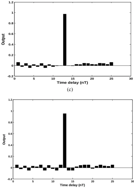
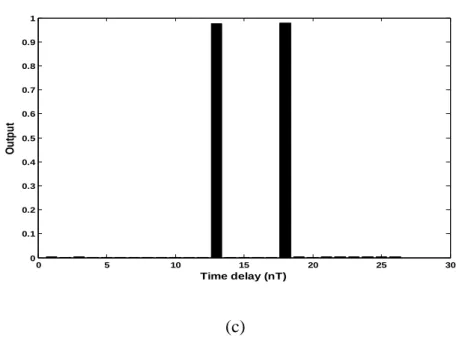
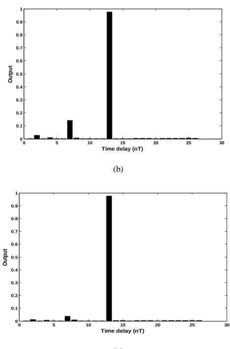
The spectral bandwidth of the coded signal is approximately the inverse of the subpulse width τ in the conventional autocorrelation output which is given in Figure 5.9(a). Where k is the index for points in the ACF, R(M) is the peak of the ACF at k = M, R(k) is the ACF for all sidelobes of the output range except the one at k = M. PSLs and codes P4s decrease with increasing code element number N (or equivalently the time-bandwidth product).
There is a scope of further improvement in all the aspects for most of the applications.