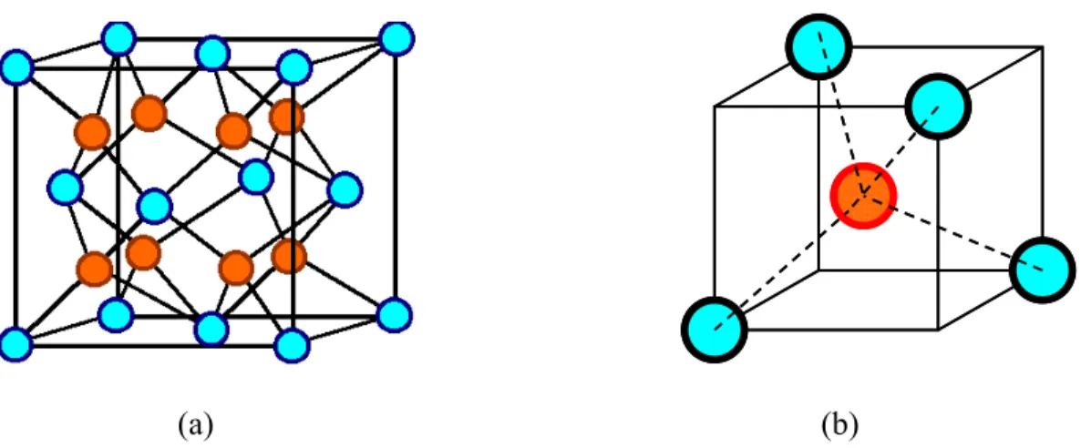
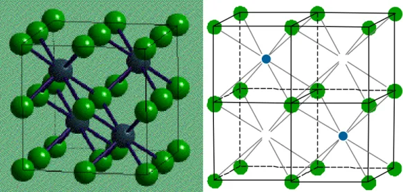
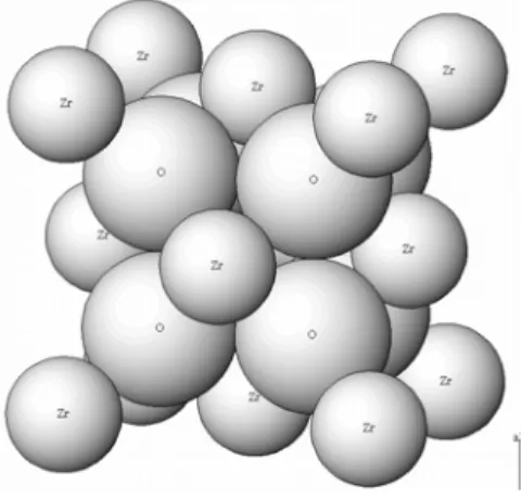
I am satisfied that the dissertation report has reached the standard of meeting the requirements of the regulations regarding the nature of the degree. In the FCC structure, Zr4+ ions occupy all the corners and the center position of the face of the cube. The fluorite structure of ZrO can be described in an alternative way where the Zr2 4+ ions are present in the center of the cube with the O2- ions present at the corner of the cube.
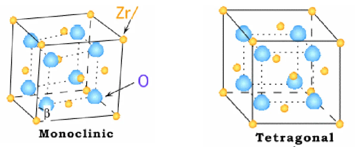
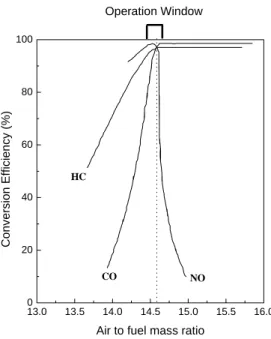
It has been observed that the martensitic transformation temperature for the t→m can be significantly reduced by adding additives with suitable properties that facilitate the stabilization of the tetragonal phase. The role of ceria in TWC is to broaden the A/F window and help maintain catalyst conversion efficiency. When using ceria-based materials in important catalytic processes such as three-way catalysis, the main concern is the thermal stability of the ceria component at elevated temperatures.
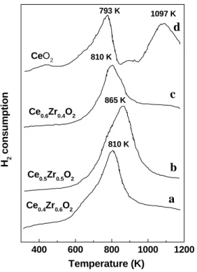
At such a higher temperature, deactivation of the catalyst may occur due to sintering of metal particles. The kinetics of the redox process is favored in the cubic phase compared to the tetragonal and monoclinic phases [16]. Sulfated metal oxides can be prepared by treating the host oxides with sulfuric acids or ammonium sulfate solutions [20].
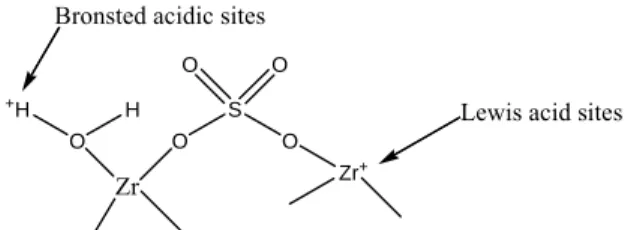
The hydrous form of the metal oxides can be prepared by heat treatment of hydroxide precursors of the metal ions at lower temperature in the range of 300-500oC. Schematic presentation of the Bronsted and Lewis acid sites in sulfated zirconia proposed by Arata and Hino. During the addition of metal salt solution, the pH of the mixture was found to decrease due to the hydrolysis of the salts.
CHARACTERIZATION OF CATALYST MATERIALS
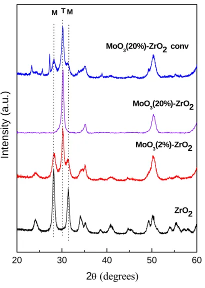
RESULT AND DISCUSSION 1 X-ray diffraction study
It was observed that the addition of Mo into the ZrO2 lattice selectively favors the formation of the tetragonal phase. The percentage of tetragonal phase present in the mixture was evaluated using the method proposed by Devassy et al [27]. It was found that all the characteristic peaks corresponding to the monoclinic phase were absent in the 20MoZr material.
The 20MoZr catalyst shows 100% tetragonal phase in the composite material, indicating that the presence of MoO3 in the ZrO2 matrix facilitates the transition from monoclinic to tetragonal phase. The XRD pattern of the 20MOZrC catalyst prepared by the wet impregnation method is shown in Fig. This observation clearly points to the effect of the preparation method on the phase content and properties of the composite catalyst.
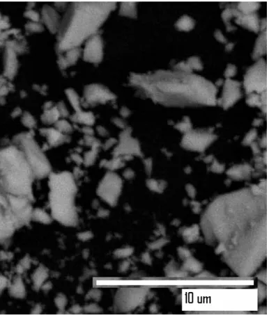
Due to the smaller grain boundary area of contact between the MoO and ZrO32 particles in the later case, the phase transition of ZrO2 is not completely completed. The volume average particle size of the composite oxides produced by pH-controlled hydrolysis is calculated using Scherrer's equation, which is found to be in the range of 10-20 nm. The MOO (20%)-ZrO3 2 composite particles are of irregular shape and size with good dispersion of the component oxides.
Since pure ZrO2 strongly absorbs infrared radiation below 700 cm-1 and therefore masks the absorption of the MoO3, the absorption data below 700 cm-1 is not collected in the present study. When 2% MoO3 was dispersed in the ZrO2 matrix, the peak pattern observed was completely different from the pure MoO3. These peak positions were found to change and shift to higher side with increase in the MoO3 content.
In addition, the 20MoZr catalyst shows an additional small shoulder at 994 cm-1 which is identical to that of the polymerized MoO3 species. At low MoO3 loading, isolated unimolecular MoO42 species are present on the ZrO2 surface together with the Mo7O246 and Mo8O266 clusters, while with increasing loading the bulk type properties of the MoO3 dominate in the composite oxide sample. The presence of different molecular species on the ZrO2 surface is shown schematically in figure 4.
CONCLUSION
In this research report, we described the synthesis, characterization and catalytic application of MoO3(x mol%)-ZrO2 catalysts with different compositions. The MoO3(x mol%)-ZrO2 catalyst was prepared by pH controlled hydrolysis of the corresponding salt precursors. For comparison, the catalyst was also prepared by conventional wet impregnation technique.
It was observed by XRD that the fabrication method plays an important role in controlling the phase transformation of ZrO2. In the former preparation case, the tetragonal phase was found to be selectively stabilized in the presence of Mo. The martensitic phase transformation of the monoclinic to tetragonal phase was achieved at much lower temperature in the presence of MoO3 in ZrO2 matrix.
The particle size calculated using Scherrer's equation was found to be in the range of 10-20 nm. Raman research performed on the sample indicates the presence of different molecular species and clusters of MoO3 on the surface of the ZrO2. At least three types of molecular species such as MoO42-, Mo7O246- and Mo8O266- were observed on the surface of zirconia.
The MoO3(x mol%)-ZrO2 materials were used as an efficient catalyst for the multicomponent condensation of aryl aldehydes, aryl ketones, asynchrolide and acetonitrile to yield the β-acetamidoketones. The protocol developed in the study is advantageous in terms of recoverable catalyst, simple, high yield, without toxic chemicals and high purity of the products.