My heartfelt thanks to you sir for the unlimited support and patience shown to me. The size of the low-pass filter designed with OCSRR and open stub is further reduced by replacing the open stubs with the defective ground structures.
Introduction
Electromagnetic metamaterials
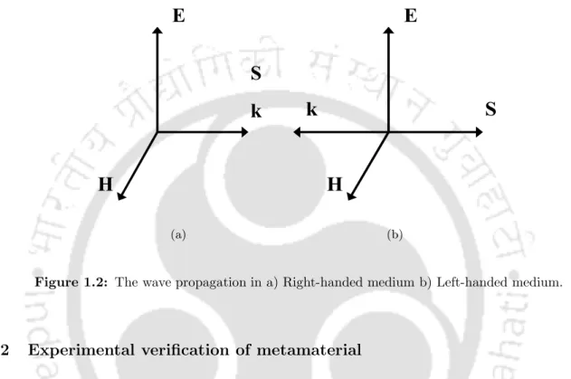
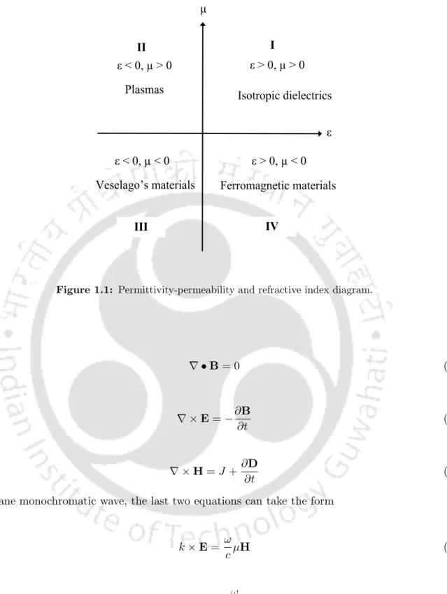
In a left-handed medium, permittivity and permittivity are negative and the phase velocity will be oppositely parallel to the direction. Shelby and co-workers proposed two-dimensional levorotatory metamaterials and experimentally verified negative refraction.
Literature review and motivation
However, the main limitation of a conventional hybrid ring is its large size due to the 2700 branch line. However, the design procedures for realizing composite right/left-handed transmission line in [29] were complicated, it also degraded the performance of the coupler.
Contribution of this thesis
Size reduction for a few reported devices (power divider using CSRR and CSR) was achieved at the expense of bandwidth reduction. Although the OCSRR size is much smaller than the CSRR size for the same resonant frequency, most of the reported applications are in CPW technology.
Thesis organization
This chapter demonstrates several performance-enhanced microwave devices such as miniaturized low-pass filters, T-Junction power divider and 1800 hybrid coupling design using OCSRR in microstrip technology.
Introduction
Split ring resonator (SRR)
Single split ring resonator (SSRR)
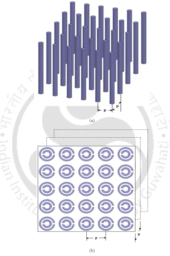
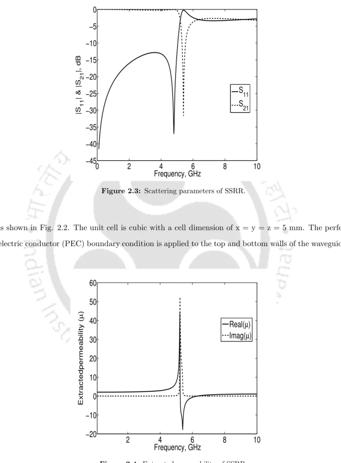
The perfect electrical conductor (PEC) boundary condition applies to the top and bottom walls of the waveguide. The S-parameters of the unit cell are calculated with a full-wave simulator and shown in fig.
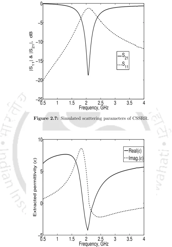
Complementary single split ring resonator (CSSRR)
It is shown that around the resonant frequency of the SSRR the real part of the medium's permeability is negative, proving that the SSRR is a µ-negative material. The scattering parameters illustrate that a stopband characteristic is present at the resonance frequency (fr) of 2.09 GHz with a maximum rejection of 25 dB.
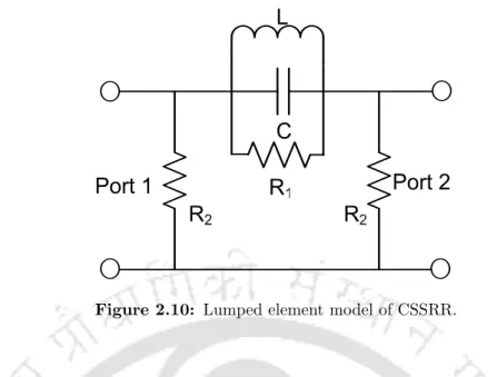
Lumped element model of CSSRR
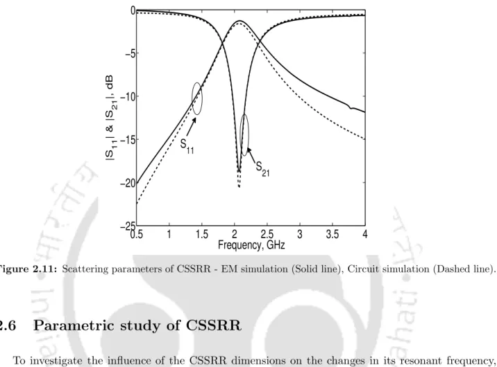
Since the simulated CSSRR scattering parameters are complex, the resulting equivalent circuit parameters are also complex. The CSSRR equivalent circuit is simulated using Ansoft Designer SV and compared with electromagnetic (EM) simulation.
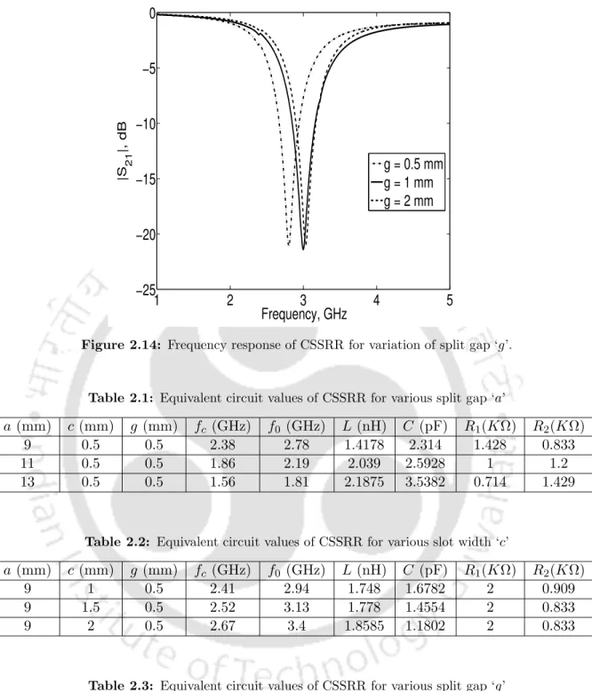
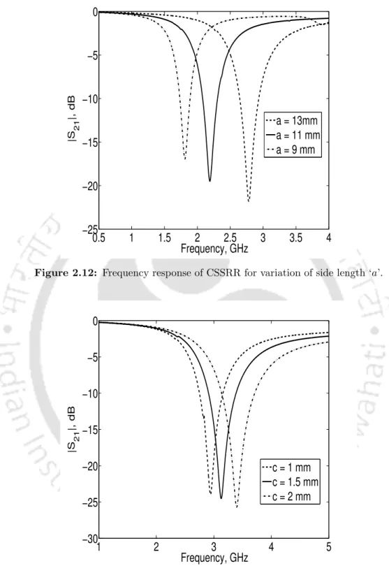
Parametric study of CSSRR
Such a detailed study will be helpful for the proper selection of CSSRR dimensions for designing CSSRRs for various applications. However, it should be noted that the formula is only useful for the rough estimate of initial dimensions of the CSSRR.
Harmonic suppression of microwave filters using CSSRR
Since we need to suppress the second harmonic (1.8GHz) of the GSM bandpass filter, a bandstop filter is first designed using CSSRR. In [51], a bandstop filter using openstub and spurline is used for harmonic suppression of BPF.
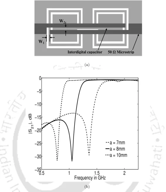
50 Microstrip
Notched ultra-wideband BPF using CSSRR
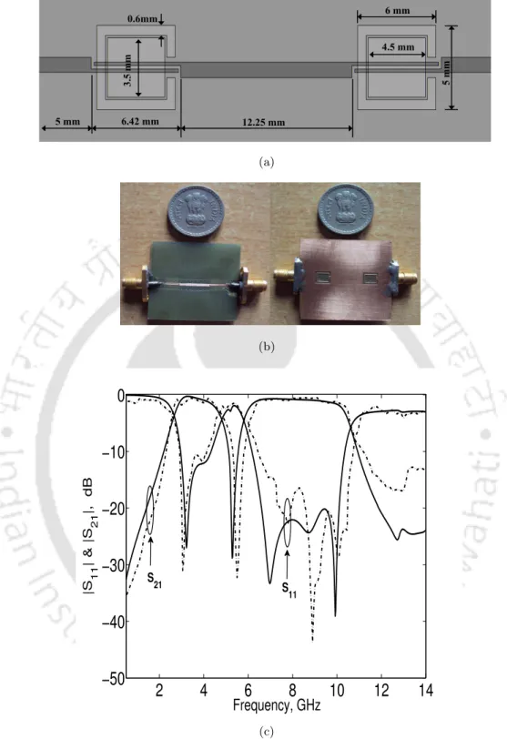
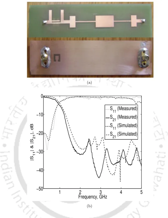
A meander line slot etched into the active area of the UWB BPF effectively removed the IEEE 802.11a (5.15 GHz to 5.85 GHz) signals from the UWB passband. To compare the performance of the CSSRR with the conventional CSRR, a CSRR resonating at the same resonant frequency as the CSSRR is simulated. The measured insertion loss of the conventional UWB BPF is less than 1.5 dB in the passband and return loss is more than 20 dB in the stopband.
All specifications of the UWB BPF with notched band and photograph of the fabricated filter are shown in Fig.
Introduction
Topology and circuit model of SRR and CSRR
Extraction of material parameters
Likewise, to study the frequency response characteristic of a CSRR, a CSRR with the following dimensions, a= 10 mm,. Since the CSRR is obtained by etching out the SRR shape from the ground plane, it occupies a lesser. The substrate used for simulation is FR4, with dielectric constant of 4.4 and thickness of 1.6 mm.
As expected, the effective permittivity of the structure shows a maximum negative value of -28.81 at the resonance.
Parametric study of CSRR
Stopband characteristics of CSRR
Multiple harmonic suppression of PCML bandpass filter using CSRR
The length of the comma is λg/4 and the width is chosen to be 10% of the width of the microstrip line. To verify the harmonic rejection capability of the proposed bandpass filter, a first-order Chebyshev PCML BPF centered at fc = 0.9 GHz with a 10% fractional bandwidth (FBW) was designed on an FR4 substrate using a standard design procedure [44, 45]. We can see from the figure that spurious bands appear at multiples of the center frequency.
So, by introducing the proposed wide-rejection band-stop filter at the input port of the PCML BPF, these unwanted harmonics can be effectively eliminated.
Summary
The proposed harmonic suppressed PCML bandpass filter operating in the 900 MHz GSM band offers more than a 20 dB rejection level up to the fifth harmonic, a maximum rejection level of 75 dB in the stopband, and a low passband insertion loss of less than 1.43 dB.
Introduction
Open split ring resonator
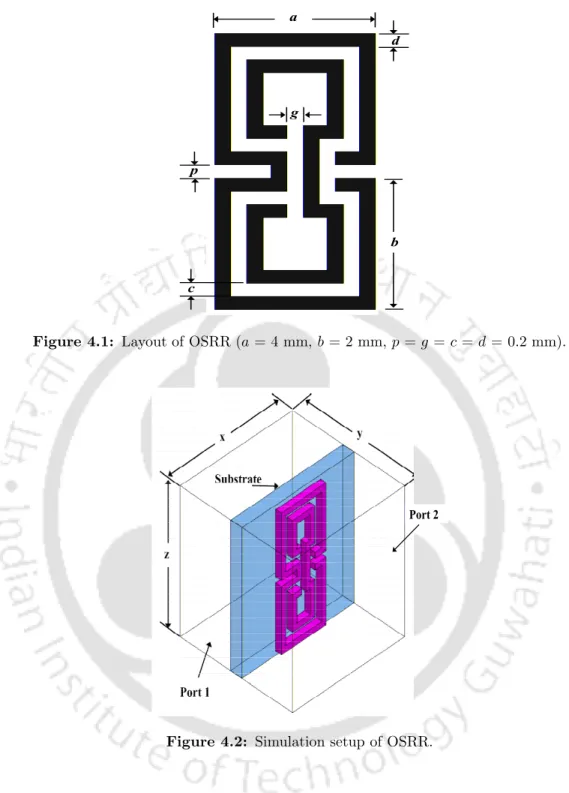
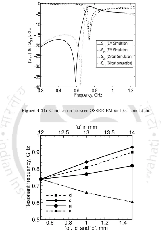
Similar to an SRR [50], if an array of the OSRR is excited by the magnetic field parallel to the ring axis, current loops are introduced into the ring. When 'a' and 'b' are increased, the equivalent inductance of the OSRR is increased and the resonance frequency, fr is decreased. When the split gap 'g' of the OSRR is increased, the reduced equivalent capacity leads to an increase infr.
A double negative (DN) cell is constructed by placing the OSRR and thin copper wire on opposite sides of the substrate.
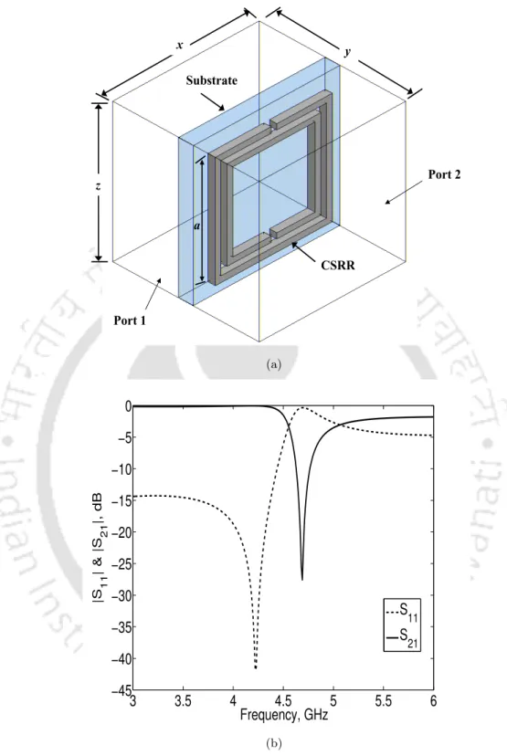
Open slot split ring resonator
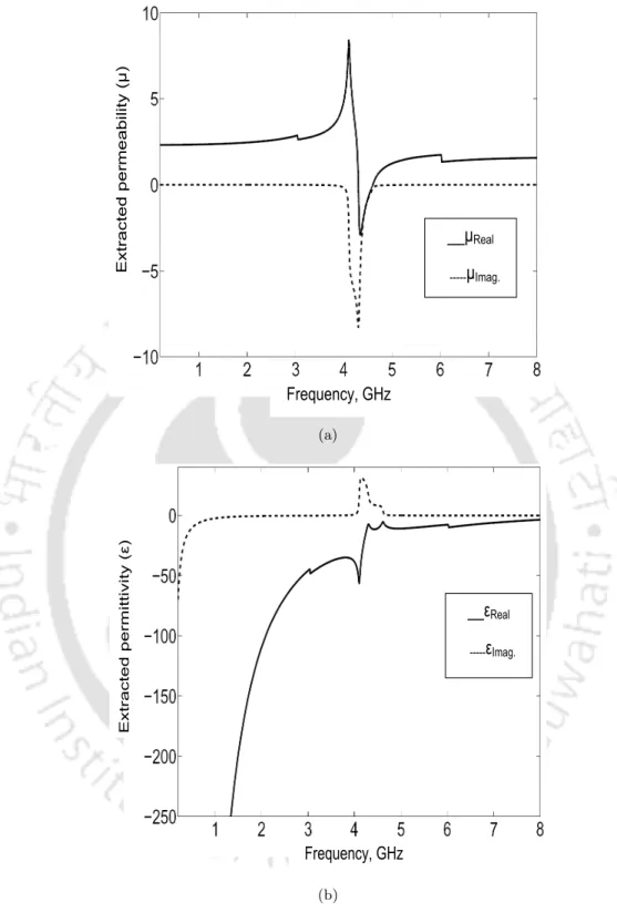
The double-negative region, where the permittivity and permittivity are negative, is observed from 4.3 GHz to 4.6 GHz. The permittivity and permittivity values of the transmission line loaded with OSSRR are obtained from the simulated scattering parameters and shown in the figure. The amplitude of the real part of the permittivity (ε) is negative just above the resonant frequency.
Lumped element model of an OSSRR
At this frequency the shunt path to ground is opened and the input impedance seen from the gate is only the series impedance of the structure. By solving equations 4.1 and 4.8, we can calculate the remaining unknowns of the lumped element model. By solving the three equations 4.1, 4.8 and 4.9 we can thus determine the values of the shunt branch element.
Through the method explained above, the aggregated element values of the proposed OSSRR structure are calculated and tabulated in table 4.2.
Parametric study of OSSRR
An increase in slot width reduces the effective capacitance of OSSRR, leading to an increase in transmission zero frequency. Thus, the desired resonant frequency can be easily obtained by tuning the dimensions of OSSRR.
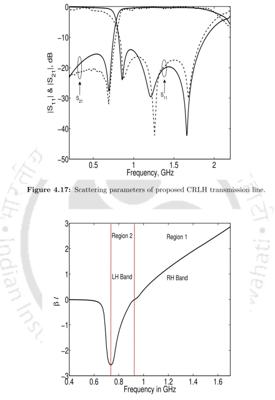
Composite right/left handed transmission line based on open slot split ring resonator
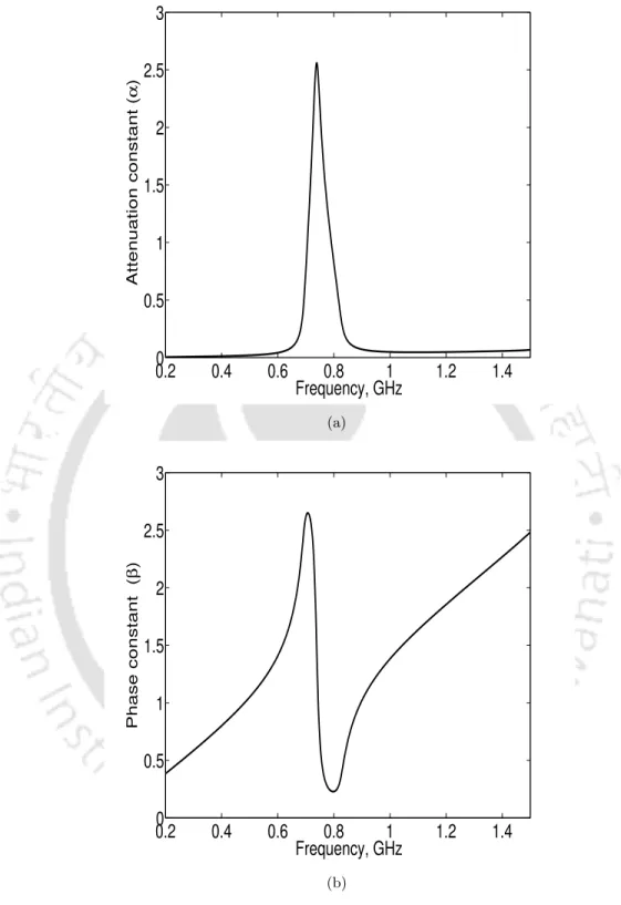
It can be seen from the figures that within the stopband the attenuation constant is dominant and the real part of the characteristic impedance decreases. To understand the wave propagation in the CRLH TL structure, the dispersion characteristic is obtained using eqn. In region 1, the phase and group velocities are in the same direction, and in region 2, both are opposite to each other.
By inspecting the dispersion relation, we observe that the proposed structure exhibits both right-handed and left-handed properties.
Compact lowpass filter design using open slot split ring res- onatoronator
Thus, for the OSSRR DGS, an approximately 28% area reduction is achieved compared to the CSRR DGS. However, OSSRR DGS has a sharper cutoff frequency than conventional DGS such as dumbbell, arrowhead, elliptical, etc. From Table 4.3, we notice that the zero transmission frequencies of the DGSs are somewhat variable and the OSSRR DGS has a good sharpness factor and fewer defects. compared to other deposit guarantee systems.
As explained in the previous section, OSSRR has a good sharpness factor and occupies less defect area, however the rejection bandwidth of OSSRR DGS is small, so this property is not suitable for LPF application.
Compact wideband bandpass filter using open slot split ring resonator and CMRC
By tuning the physical parameters of the OSSRR, the desired 3 dB cutoff frequency can be easily obtained. Therefore, by periodically increasing the value of inductance and capacitance of the transmission line, slow wave effect can be achieved. As the length of the cell is increased, the stopband frequency moves towards the bottom.
Therefore, to avoid increasing the cell length for a lower frequency, the cell width is increased.
Design of bandpass Filter
The cutoff frequency of BPF can be varied by changing the cutoff frequency of LPF or HPF. The Type 2 BPF has 76% FBW and covers 47% less area than the traditional PCML BPF with the same center frequency at 2 GHz. The turn-on losses of Type 1 and Type 2 filters are less than 1.48 dB and 1 dB respectively.
Summary
Introduction
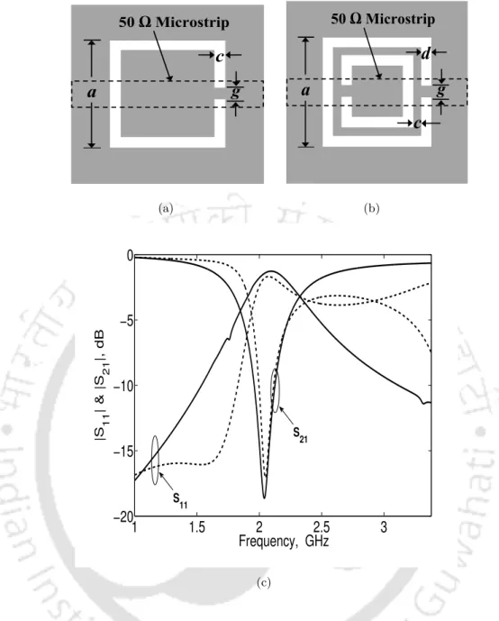
Conventional open split ring resonator and open complementary split ring resonator
OCSRR and its modeling
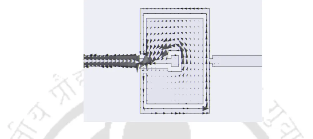
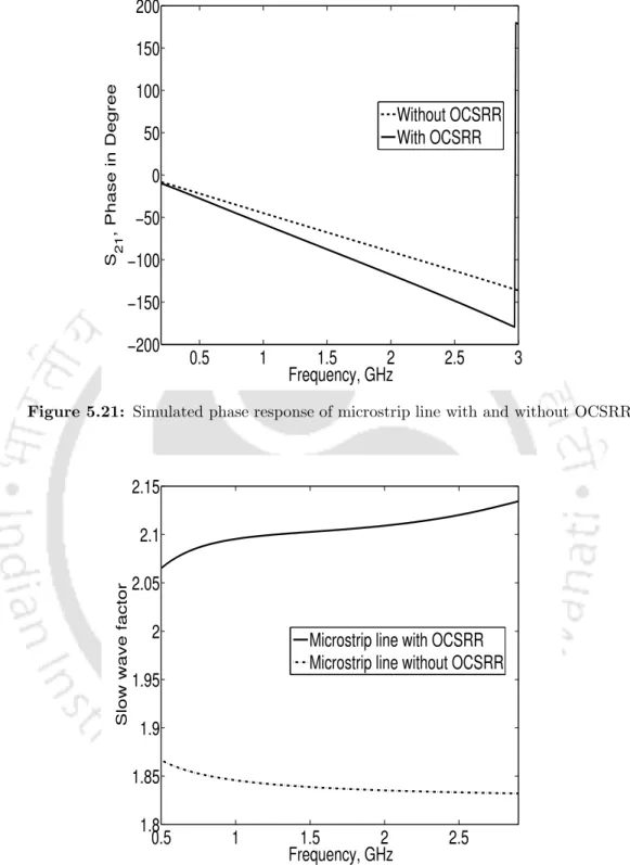
The graph shows that the SWF of the microstrip line loaded with the OCSRR is increased by 73% compared to the microstrip line without OCSRR. Thus, the increase in SWF validates the reduction capability of the OCSRR for microwave applications. The equivalent circuit of the OCSRR embedded microstripline and the Butterworth low-pass filter unipolar prototype is shown in Fig.
The reactance value of the OCSRR unit can be expressed as follows,. whereω0 is the resonant frequency of the parallel LC circuit, which corresponds to the transmission zero location of the OCSRR.
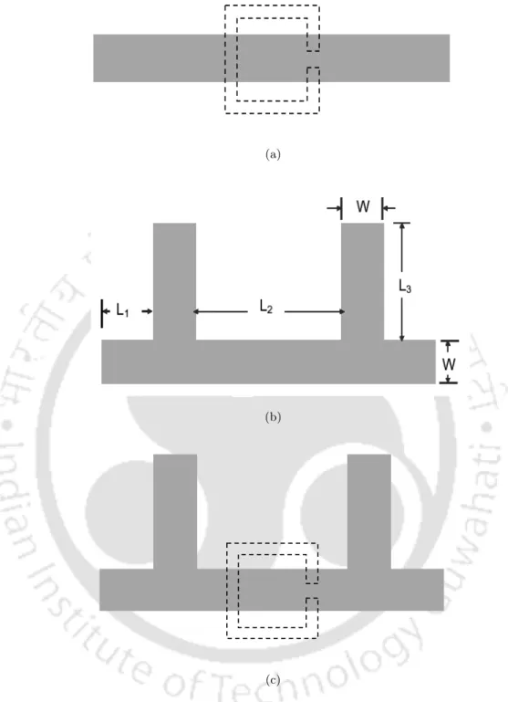
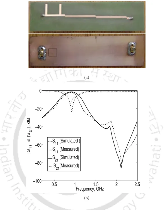
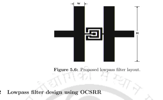
Improved stopband lowpass filter using OCSRR
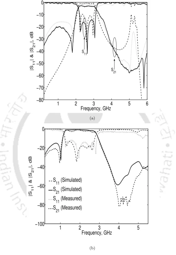
It is observed that by increasing the stub length, the cut-off frequency moves towards the lower end and also the sharp rotation of the speed is achieved. Similarly, the transmission responses of the structure for different stub widths W = 1 to 4 mm are shown in Figs. The measured filter stopband rejection is better than 30 dB up to 6 GHz, which is nearly six times the cutoff frequency.
The proposed low-pass filter result is compared with a portion of previously reported work and is shown in Table 5.1, where λg is the guided wavelength of a 50 Ω microstrip line at the cutoff frequency.
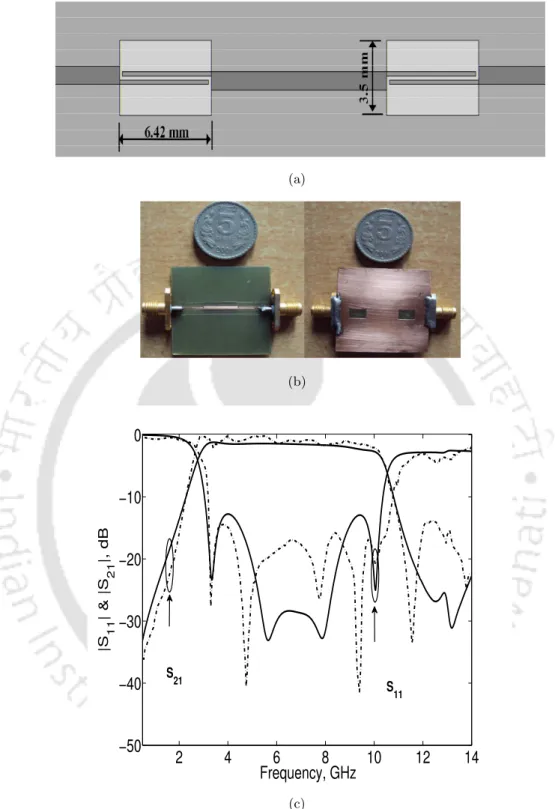
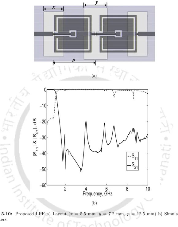
Ultra-wide stopband lowpass filter using open complementary split ring resonator and defected ground structures
The filter's simulated stopband rejection is better than 20 dB up to 10 GHz, which is nearly ten times the cutoff frequency. Compared to the work already reported, the proposed filter size is compact and offers a broad stopband rejection. This proposed low-pass filter is much superior to the existing high-efficiency filters reported by Wu [88] and Aznar [36] in terms of stopband rejection width.
Compact, harmonic suppressed power divider using open com- plementary split ring resonator
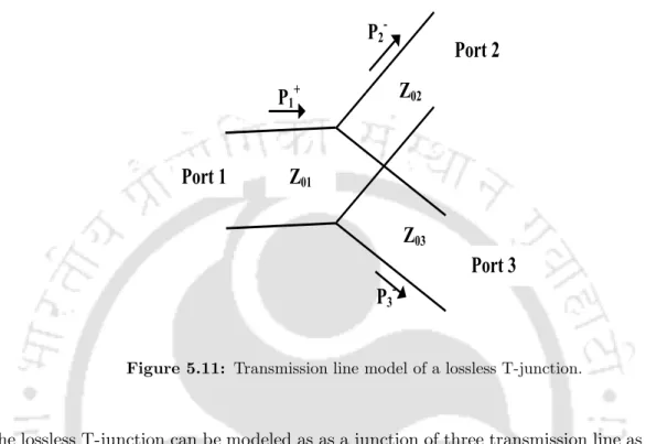
The lossless T-junction can be modeled as a junction between three transmission lines as shown in fig. When ports 2 and port 3 are terminated in matched loads, the input impedance at port 1 must be equal to Z01. The equally divided conventional power divider is designed using two quarter wavelength transmission line with characteristic impedance of 70.7 Ω.
The simulated results of the conventional equally divided T-junction power divider are shown in Fig.
Z OCSRR Z in
Size reduced and harmonic suppressed rat race coupler
The circuit area of the C-SCMRC rat-race coupler is only 45% of a conventional coupler. The slow wave effect of the embedded OCSRR microstrip line is used to design such a compact ring hybrid. The slow wave factor of the embedded OCSRR line is higher than that of the conventional microstrip line.
The measured phase response of the proposed ring hybrid for the gate 1 and gate 4 excitations is shown in Fig.
Summary
Conclusions
The fractional bandwidth of the filter can be easily varied by varying the cutoff frequencies of the LPF and HPF sections. The proposed filter has sharp cut-off characteristics and is 17.5% smaller than the conventional step-impedance low-pass filter and 8% smaller than the CSRR DGS LPF. A wide stopband, sharp cutoff and compact low pass filter is designed using open complementary split ring resonator (OCSRR) and open stub.
The filter size is very small (0.22 λg × 0.18 λg, where λg is the guided wavelength at the cutoff frequency).
Suggestions for future work
Sorolla, “Effective negative-ε stopband microstrip lines based on complementary split-ring resonators,” IEEE Microwave and Wireless Components Letters, vol. Chang, “Compact microstrip frequency filter using open stub and spurline,” IEEE Microwave and Wireless Components Letters, vol. Guan, “A cut-band coplanar ultra-wideband bandpass filter,” IEEE Microwave and Wireless Components Letters, vol.
Sanyal, “A new ground defect structure for planar circuits,” IEEE Microwave and Wireless Components Letters, vol.