Introduction
Historical development
The power contained in the wind is the kinetic energy of the air mass flowing per unit of time. This results in a change in the force exerted by the wind on the rotor shaft.
Power Contained in the wind
Wind Turbines
Basic concepts
If the energy captured by the wind is used for processing purposes such as cutting timber or grinding stone, the machine is called a windmill. If, on the other hand, it is used for pumping water, it is called a wind pump.
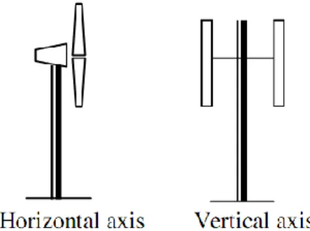
Horizontal axis wind turbines
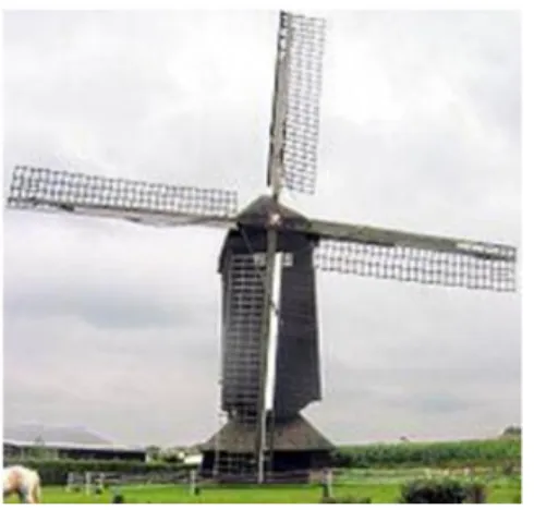
- Dutch windmills
- Multi-blade water-pumping windmills
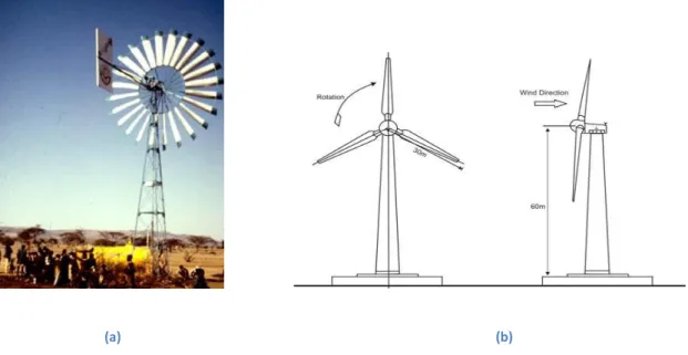
- High speed propeller type wind machines
- Advantages of horizontal axis wind turbines
- Disadvantages of horizontal axis wind turbines
Dutch windmills were the forerunners of the windmills widely used in Europe to grind grain. As the name suggests, the Multi-blade Water Pump Windmills have a large number of blades. The location of the mill is not governed by the availability of wind, but by the availability of water.
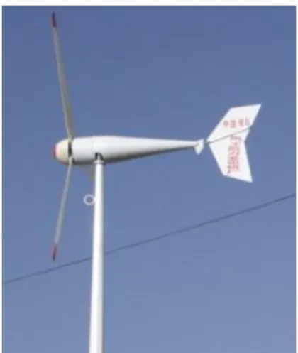
A tail blade is usually fitted to the turbine to orient it to face the wind. Instead of working on the thrust force of the wind, as in previous cases, this turbine acts on the aerodynamic forces of the wind. Wind turbines operating on propulsive forces have been found to operate at a lower efficiency than those operating on aerodynamic forces.
Variable speed is possible by which the angle of attack of the turbine blades can be controlled. Since the blades are present at a considerable height, they can catch stronger winds. Rotations of blades lead to cyclic stresses and vibrations in the main bearings of the turbine.
Vertical axis wind turbines
- Darrieus type wind turbine
- Savonius type wind turbine
- Giromill type wind turbine
- Advantages of VAWTs
- Disadvantages of VAWTs
These are drag-type turbines that work entirely on the propulsive force of the wind. These parameters are used in the control of the wind turbine models presented in the following chapters. Wind rotor strength is the ratio of the projected blade area to the intercepted wind area (Bhadra S N, 2010).
The blades of the rotor are shaped in such a way that when the wind speed exceeds a certain level, stalling occurs. 3.3 (a small turbine mounted perpendicular to the main turbine) or, in the case of wind farms, by a centralized wind direction detection instrument (Stiebler). In this region the Cp is lower than the maximum and the power output is not proportional to the cube of the wind speed (Bhadra S N, 2010).
In this model, he suggests that the pitch rate of the blades is kept constant. The gains of the PID controller are varied one by one and the response was recorded. Therefore, the values of profits Kp, Ki and Kd were not changed in any time cycle.
Control Techniques for HAWTs
Some Relevant Definitions
- Solidity
- Tip Speed Ratio
- Power Coefficient
Projected blade area here refers to the area of the blade that meets the wind or is projected into the wind direction. For high-speed machines with a horizontal axis, it lies between 0.01 and 0.1; for darrieus rotor also is of the same order (Bhadra S N, 2010). Thus, only high-speed propeller type and Darrieus wind turbines are suitable for electricity generation.
The tip speed ratio (TSR) of a wind turbine is defined as the ratio of the speed of the tip of the blade to the speed of free wind. The peak speed ratios of the savonius rotor and the multi-bladed water-pumping wind turbines are generally low as they operate at low speeds. In these two types of wind turbines, the outer tip rotates much faster than the wind speed due to their aerodynamic shape.
Power coefficient of a wind turbine is the instantaneous efficiency of converting wind energy into mechanical energy of the shaft. The power coefficient is just the efficiency of converting wind energy into mechanical energy of the shaft. In high-speed horizontal-axis machines, the theoretical maximum power coefficient is given by the betz limit which is 0.59.
Control techniques for wind turbines
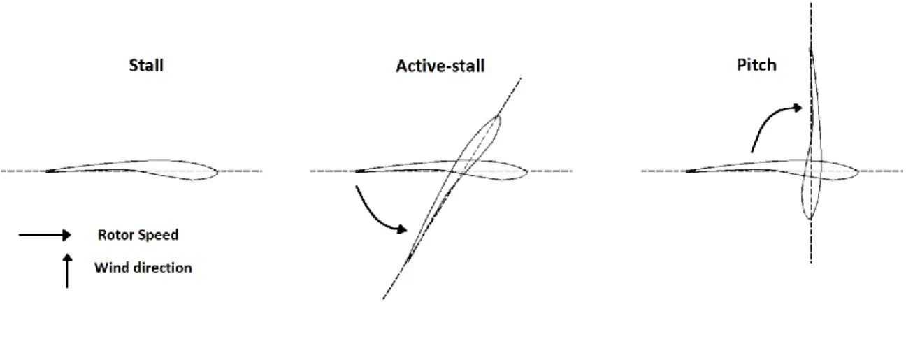
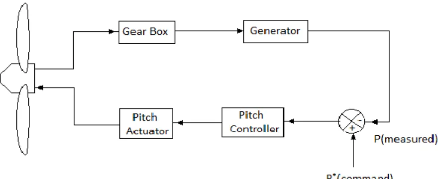
- Pitch Control
- Stall control
- Power Electronic Control
- Yaw Control
At high wind speeds, pitch control can be used to keep the power output close to the rated power of the generator. Due to the presence of gusts, the instantaneous power fluctuates around the rated average value of the power. Stall control is the simplest control technique for a wind turbine where the blades are bolted to the hub at a certain angle.
Instead of natural pitching, this system uses pitching to actively control the pitch of the blade. The change is therefore speed and thus the final speed of rotation of the turbine can be controlled. Continuous control of the rotor speed by this method leads to continuous fluctuation of the power output to the grid, which is not desirable.
Downwind turbines have an inherent property to face the wind as the thrust force automatically pushes the turbine downwind. The rotor is made to turn away from the wind direction at high wind speeds, thus reducing mechanical power. However, this method is rarely used where pitch control is available, because of the stresses it produces on the rotor blades. Churning often produces loud noise and it is desirable to limit the churning speed in large machines to reduce noise (Bhadra S N, 2010).
Control Strategy
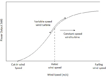
We saw earlier that the maximum power point is reached at a certain (constant) value of TSR. Therefore, in order to track the limit point of maximum power, it is necessary to constantly change the rotational speed in proportion to the wind speed (Bhadra S N, 2010). c) In strong wind, the rotor speed is limited to a maximum value, depending on the design limitation of the mechanical components. The main disadvantage of the actuator of the first embodiment is that we cannot predict which tilt angle will be required when the actuator reaches the command value.
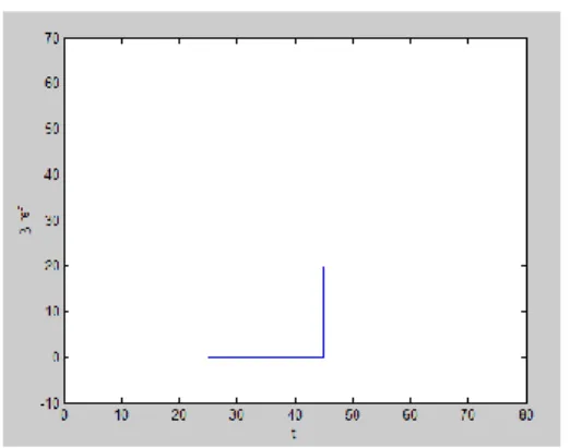
The third model investigated is the PID control-based Pitch Actuator System. The power characteristics of the above model are shown in Figure 5.1: Power characteristics of a horizontal axis wind turbine. Based on the values of the calculated time response parameters, tune the values of Kp, Ki and Kd for the next time cycle.
The system also faces the problem of sudden stops in the rotation of the blades when the reference pitch angle is reached. However, fine-tuning of the controller parameters online is usually necessary to obtain acceptable control performance (Gopal, 2010). This led us to try to devise an adaptive PID algorithm where the values of time response parameters of the pitch actuator system are observed and the fine-tuning of the controller parameters is performed.
Pitch Actuator System Modeling
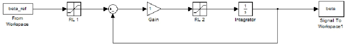
Proportional Control based Pitch Actuator System
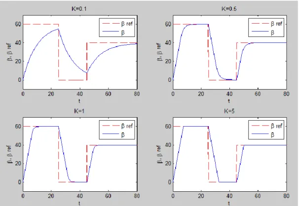
The block named "RL2" is also a saturation filter which defines the pitching speed limits. The maximum and minimum allowable values for pitching speed in this system are respectively 8 degrees per second. time unit and -8 degrees per unit of time. The response of this system has been observed for four different values of proportional gain.
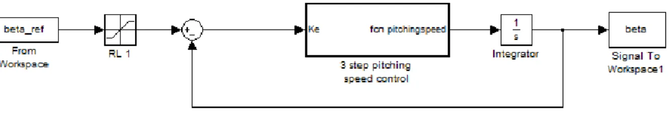
Pitch Actuator System with constant value of pitching speed
The response of this system was observed for three different values of pitch speed viz. It can be seen that if the stab speed is set too low, it cannot detect the input signal effectively, causing an error to prevail at all times. Also, a very high value of pitch speed requires a very high torque to be exerted on the blades, which can lead to unwanted stress on the blade and actuator.
PID Control based Pitch Actuator System
As can be seen, the system produces a good response in the first case where the gains are Kp=2, Ki=0.01 and Kd=0. In the next chapter, an adaptive PID approach is proposed where the gain values are revised after each input step based on the time response parameters. As mentioned before, the power contained in the wind is given by. and the electrical power generated by the wind turbine is given by.
The following model was used to approximate the relationship of Cp with TSR and pitch angle. Set the first set of values for Kp, Ki and Kd. Read the wind speed value. NOTE: It is assumed that the tilt angle input can only accept input values that are multiples of 5.
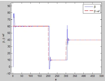
The spikes are visible in the response due to the implementation of a discrete time PID algorithm instead of a continuous time model as used in the previous chapter. In the event that the derived gain is at its maximum allowable value and crosses the peak overshoot 20, the value of proportional gain is reduced. The response obtained in this case is a very stable one and the values of time response parameters in each time cycle are found to be within acceptable limits.
Adaptive PID: A suggested approach to Pitch Control of HAWT
Wind Turbine Model
Algorithm
Send this pitch value as a command value to the PID controller for the duration "t1". From the PID response, estimate rise time tr (or peak time tp), peak overshoot Mp, settling time ts and steady state error ess. The system is allowed to operate for a period of 100 time units in each cycle, after which the time response parameters are evaluated and necessary changes are applied to the proportional, integral and derivative gains.
As shown in the table, when the peak excess value Mp is greater than 20, a derivative component is introduced to compensate. The proportional control based pitch actuator system has the advantages and disadvantages of any proportional controller. If the selected gain is kept low, the system response will be slow and a steady-state error will occur.
The disadvantage is that when the response needs to be faster, the system cannot deliver. The adaptive PID system model proposed here can be tested in real time, where the monitoring and actuation system can be able to operate simultaneously, so that the system can respond faster and a stable set of gain values is obtained in a shorter time. So improvements can be made to the tuning algorithm to stabilize an oscillating system.
Conclusion
Conclusion
The constant opening rate model has the merit of being extremely simple in design and implementation.
Future Work