Next, we consider two coaxial vertical cylinders—a mounted porous cylinder and a bottom-mounted solid rigid cylinder. Waves with truncated partially porous cylinders at finite depth 75 4.1 Floating partially porous cylinder piercing the surface. Variation of the dimensionless hydrodynamic force on the upper part of the cylinder. vs. wavenumber for different values of G corresponding to h1/h Comparison with the first model and the second model for the lower part of the cylinder 52 2.21 Comparison with the first model and the second model for the upper part of the cylinder 52 3.1 Floating composite porous cylinder at finite depth with the top bottom.
Preamble
In Euler's description, three types of curves are usually used to describe fluid motions - flow lines, path lines, and tracks. Cauchy-Poisson analysis is now recognized as an important milestone in the mathematical theory of initial value problems. In the next section, a brief description of the basic equations and conditions in the theory of linearized water waves for the case of constant depth is presented.
Relevant equations and conditions
When the wavelength of the water wave is much greater than the water depth, it is called a shallow wave (or long wave). Therefore, the problems in water wave mechanics are usually modeled for small amplitude waves, i.e. by applying linear wave theory. In this thesis, linearized water wave theory is used to tackle all the problems taken up.
A brief discussion on fluid flow through porous media
Secondary porosity (Porosity that grows after the deposition of rock or any other natural porous material.). Total porosity (It is the ratio between the total pore space in the rock and its volume). The parameter G can be considered as the Reynolds number for the flow passing through the fine pores of the wall (Chwang [7]).
Interaction of linear water waves with a structure
In linearized water wave theory, this condition is applied to the equilibrium surface of the structure, denoted by SB. The potential ΦS is a solution to the scattering problem in which the structure is attached to the waves and can be further decomposed as In general, the motion of a structure will be a combination of motions in all these directions, and the velocity of a point on the surface, measured normal to the surface, can be written as

Evaluation of velocity potential in cylindrical coordinates
Estimation of Velocity Potential in Cylindrical Coordinates 17from the density of the body, the added mass can often be greater than the mass of the body. Furthermore, k0 can take completely imaginary values, say −ik, in which case k is the positive root of the dispersion relation. Evaluation of the Velocity Potential in Cylindrical Coordinates 19. which is a modified Bessel equation. 1.45) for some constants C and D, and where Im(.) and Km(.) denote the modified Bessel functions of the first and second order m, respectively.
Roots of the dispersion relation
The velocity potential associated with all the problems in the subsequent chapters of this thesis is evaluated in a manner as outlined above.
Brief review of previous works
He also established the importance of the wave effect parameter and the porous effect parameter. They found that the permeability, size and location of the porous zone have a large effect on the hydrodynamic forces. It was found that higher values of reflection coefficient correspond to lower values of porosity.
Main motivation for the current work
Offshore wind power or wind energy can be harnessed by installing wind farms in any large body of water, usually in an ocean on the continental shelf. The sea southwest of the Gulf of Cadiz in Spain is one such primary source of wind energy. Such a co-location of two activities in aquaculture and wind energy production will result in reducing expenses on both public and private fronts.
![Figure 1.3: The Mutriku Wave Energy Plant (Courtesy Mustapa et al. [36])](https://thumb-ap.123doks.com/thumbv2/azpdfnet/10558373.0/63.892.173.758.393.989/figure-mutriku-wave-energy-plant-courtesy-mustapa-et.webp)
Outline of the thesis
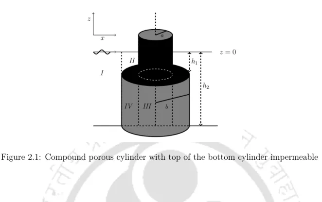
The bottom (0≤r ≤ b) and the top (a ≤r ≤ b) of the lower cylinder and the side wall of the upper cylinder are impermeable. Using matching conditions along the region boundaries, a system of linear equations for the unknown coefficients is derived and solved. A set of hydrodynamic force and wave attack values are obtained for different radii, different drafts and different porosity of the cylinder.
To confirm our result, we compare our result with a composite floating cylinder when the sidewall of the bottom cylinder is impermeable. In both cases, the configuration of the composite cylinder is such that it consists of an impermeable inner cylinder rising above the free surface and a coaxial cut porous cylinder around the bottom of the inner cylinder, with the top of the porous cylinder being impermeable. Appropriate matching conditions are applied at the interface of the regions to obtain a system of linear equations for the unknown coefficients and solve it.
By considering different sets of values of the radius and the porous coefficient of the cylinder, the hydrodynamic force and wave run-up are evaluated. The configuration of the partially porous composite cylinder is such that it consists of an impermeable inner cylinder that rises above the free surface and a coaxial truncated porous cylinder around the lower part of the inner cylinder with the top of the porous cylinder being impermeable is. Several numerical experiments show the effect of different parameters, such as porosity of the upper cylinder, draft ratio, the ratio of radii of the upper and lower cylinders and the depth of water on hydrodynamic force and wave run-up.
The boundary conditions at the free surface and the seabed can be written as 2.5) The boundary conditions on the composite cylinder's impermeable surfaces can be
Diffracted potentials
The potential given by equation (2.18), together with Um(4)(σjr), is connected to a specific resonance phenomenon. The first term on the right-hand side of the potential given by equation (2.18) is the most important contribution to the wave motion inside the cylinder, while the other terms describe waves localized nearer=a. Each of the different modes (m) resonates at different wavenumbers near the roots of Jm0 (ka) = 0 where the roots correspond to the standing waves inside a cylindrical structure.
This is what is known as the attenuation mode resonance when the water movement occurs mainly in the natural motion of the moon pool and due to the water moving back and forth between the vertical walls. The similar phenomenon of resonance due to fading can also be observed in the works of Garrett [15] and Mavrakos [29].
Solution for the unknown coefficients
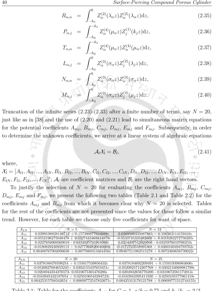
Then, to determine the unknown coefficients, we arrive at a linear system of algebraic equations. To justify the choice of N = 20 for the evaluation of the coefficients Amj, Bmj, Cmj, Dmj, Emj and Fmj, we present the following two tables (Table 2.1 and Table 2.2) for the coefficients Amj and Bmj from which it becomes clear why N is chosen = 20. The tables for the rest of the coefficients are not presented since the values for them follow a similar trend.
Water wave height for outer and inner areas given by ηj(r, θ, t) = Re[ζj(r, θ) exp(−iωt)]for j = 1,2,3, can be evaluated by the dynamic free surface condition. The total hydrodynamic force in the wave propagation direction on the upper and lower cylinder can be evaluated by integrating the pressure distribution on the structures.
Validation
Results and discussion
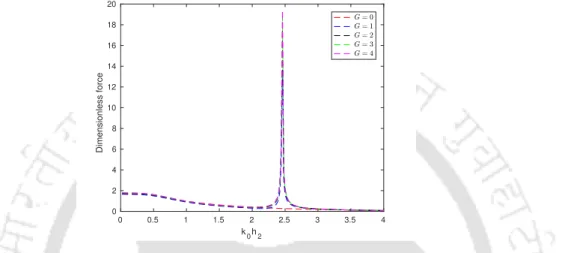
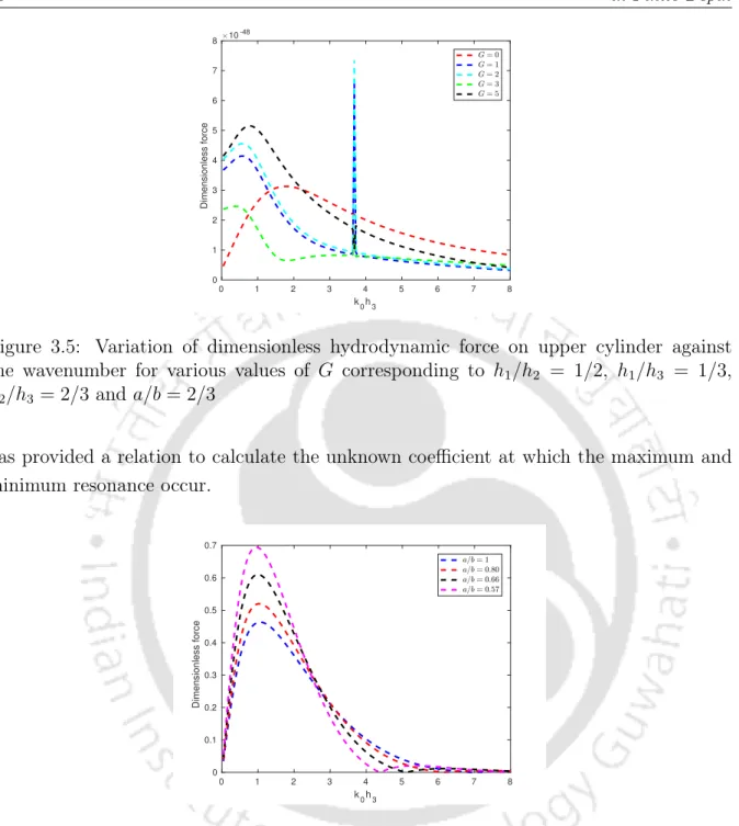
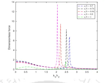
This unusual behavior in the vicinity of 2< k0h2 <3 is due to the wavenumber corresponding to a wavelength close to the wavelength of free fluid motion. This unusual behavior near k0h2 = 3.8 occurs due to the wave number corresponding to the wavelength close to that of the free fluid motion. It is observed that, except for G = 0, the peaks of the force on the upper cylinder increase with increasing porosity values of the lower cylinder.
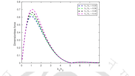
The key observation is that the higher values of the force occur within lower values of h1/h2. The key observation is that the force on the bottom cylinder decreases as porosity increases. The influence of the values of G on the maximum run-up is not very great.
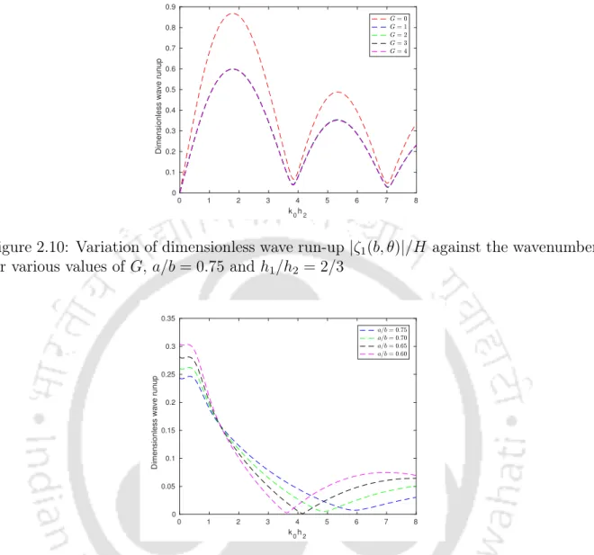
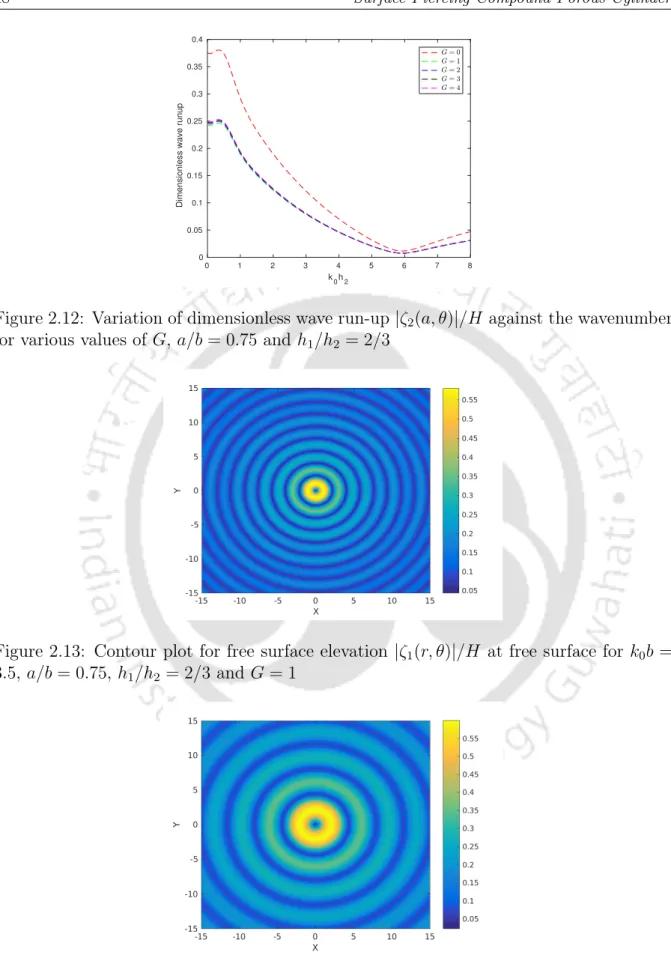
In Figure 2.11, the maximum dimensionless wave run-up amplitude |ζ2(a, θ)|/H is investigated in the outer region. In Figure 2.12, the maximum dimensionless wave run-up amplitude |ζ2(a, θ)|/H is investigated in the outer region. The most important observation is that the run-up increases for increasing values of the porosity.
Figures 2.13 and 2.14 discuss contour plots of the free surface height near the free surface for two different frequency values.
Particular case: semi-porous single cylinder
Mathematical formulation
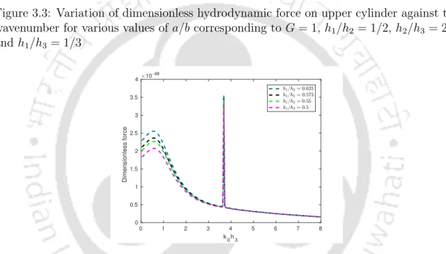
In Figure 2.16 the hydrodynamic force on the lower part of the cylinder is plotted against the wave number for different values of h1/h2 corresponding to G = 1. In Figure 2.17 the hydrodynamic force on the upper part of the cylinder is plotted against the wave number . wavenumber for different values of h1/h2 corresponding to G = 1. Figure 2.18 plots the hydrodynamic force on the lower part of the cylinder.
In Figure 2.19, the hydrodynamic force on the upper part of the cylinder is plotted against the wave number for various values of G corresponding to h1/h2 = 1/2. It should be noted that the higher values of the force occur within lower values of h1/h2. This shows the appearance of the highest value of the wave run-up in the vicinity of k0h3 = 1.5.
It is observed that the moment at z = −h1 increases as the porosity of the outer cylinder decreases. It is observed that the maximum value of the run-up occurs near k0h2 = 0.5. The boundary conditions that must be met on the surface of the porous cylinder are the following:
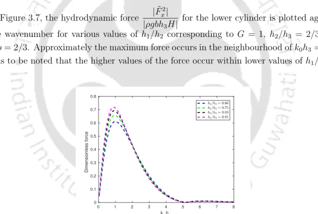
This shows that the porosity of the structure has a fair influence on the wave run-up. The figure shows that the hydrodynamic force acting on the inner cylinder takes increasing values corresponding to a reduction in the values of the radius ratio. Then the effects of the various useful parameters on the hydrodynamic forces and wave run-up are investigated.
It can be seen from Figure 6.14 that the maximum value of the added mass is reduced for higher values of h2/h3. Figures 7.9 and 7.10 show contour plots of the wave run-up closer to the free surface corresponding to two different frequency values.