The effect of desorption temperature and overall heat transfer coefficients on the amount of hydrogen desorbed and the average bed temperature were studied during the dehydration process. Based on the above discussions it can be concluded that MHHSD with ECT can be effectively used as a safe storage medium for hydrogen storage.
Nomenclature
ECT : Integrated Cooling Pipes FDM : Finite Difference Method FVM : Finite Volume Method HFT : Hot Fluid Temperature HPMH : High Pressure Metal Hydride HSC : Hydrogen Storage Capacity HTF : Heat Transfer Fluid.
Contents
List of Tables
Introduction
- Preface
- Hydrogen as an alternative energy
- Metal hydrides and thermodynamics of hydride formation
- Classification of metal hydrides
- Applications of metal hydrides
- Motivation of thesis
- AB 2 , AB – based alloys
- Thesis structure
- Summary
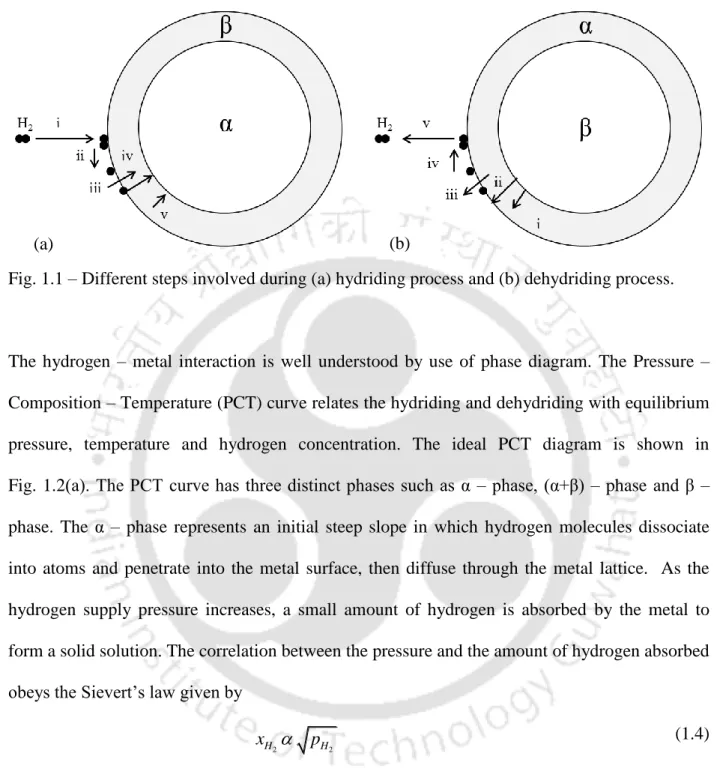
After reaching the steady state, metal hydride formation begins and the α phase undergoes a phase transition (α + β) - phase. M is the molecular weight of hydrogen and Ma is the molecular weight of the metal hydride.
State-of-the-Art
Preface
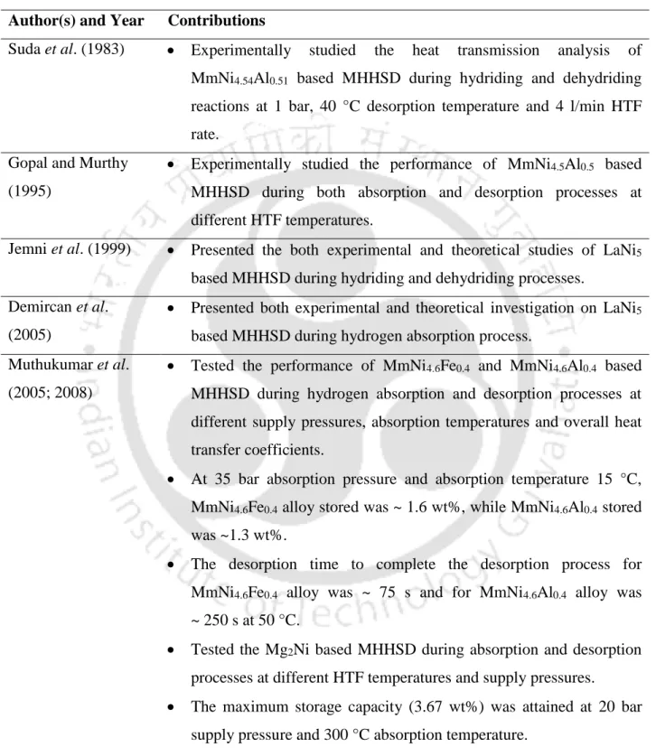
The reaction kinetics on hydriding and dehydriding characteristics
They reported that the reaction kinetics decreased by substituting Co and Al for Ni. It was found that the rates of hydration and dehydration were controlled in the phase transmission region .They.
Studies on coupled heat and hydrogen transfer characteristics in lab–scale
- Numerical investigations on hydriding/dehydriding characteristics of MHHSD
- Heat transfer augmentation techniques
Sun and Deng (1988) developed a 1-D transient mathematical model for predicting the heat and mass transfer characteristics of TiMn1.5-based MHHSD during hydration and dehydration processes at different temperatures (30 °C, 40 °C, 50 °C). 2007) developed a 2-D mathematical model to investigate the heat and mass transfer characteristics of MMHSD based on MmNi4.6Al0.4 during the hydrogen absorption process at different supply pressures and absorption temperatures using FLUENT 6.1.22.
Experimental studies on lab-scale prototype metal hydride based hydrogen storage device
- Experimental studies on MHHSD with heat transfer enhancement techniques
1987) Developed a 1-D mathematical model for evaluating heat and mass transfer properties of LaNi4.7Al0.3 and LmNi5-based MHHSD during hydration process at different temperatures. Developed a 2-D mathematical model for investigating the heat and mass transfer properties of MmNi4.6Al0.4-based MHHSD during hydration and dehydration processes at different feed pressures and absorption temperatures using FLUENT 6.1.22. Experimentally studied the performance of MmNi4.5Al0.5 based MHHSD during both absorption and desorption processes at different HTF temperatures.
Tested MGHSD based on Mg2Ni during absorption and desorption processes at different HTF temperatures and feed pressures.
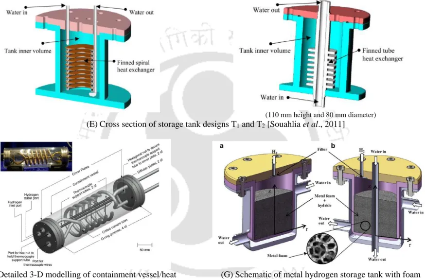
Some metal hydride reactor designs reported in the literature
The rate of hydration was greater in the coil heat exchanger than in the finned tube heat exchanger. Experimentally studied the development and thermal performance of 4 kg Ti1.1CrMn-based MHHSD with a coiled-tube heat exchanger during the hydration process. Developed a 3-D numerical model for solving the coupled heat diffusion and hydration reaction equations of Ti1.1CrMn-based MHHSD.
Presented both experimental and theoretical studies on the dehydration performance of Ti1.1CrMn-based MHHSD with modular tube fin and simpler coiled tube design.
Literature closure
For high temperature MH alloys, the radiant heat flux term must be included in the energy equation. No mathematical model has been reported (except Askri et al. 2003) with inclusion of the radiant heat flux term in the energy equation. This shows that there is a lack of studies on MHHSD with ECTs at lower supply pressures in the range 5 - 30 bar and at near ambient temperatures.
To study the absorption and desorption characteristics of laboratory scale prototype MHHSD by considering the volumetric radiation effect in the energy equation.
Summary
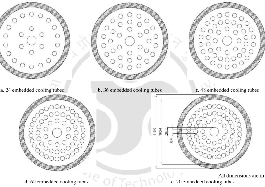
In view of the above conclusion of the literature review, the following aspects are considered in the Ph.D. To develop a 2D mathematical model for optimizing the number of embedded cooling tubes (ECT) and their arrangements in a metal hydride-based hydrogen storage device (MHHSD). To develop a 3D mathematical model for predicting the absorption and desorption characteristics of MHHSD with optimized configuration of ECT under different operating conditions.
To test the performance of the absorption and desorption characteristics of MHHSD with ECT under different operating conditions.
Heat and Mass Transfer Models
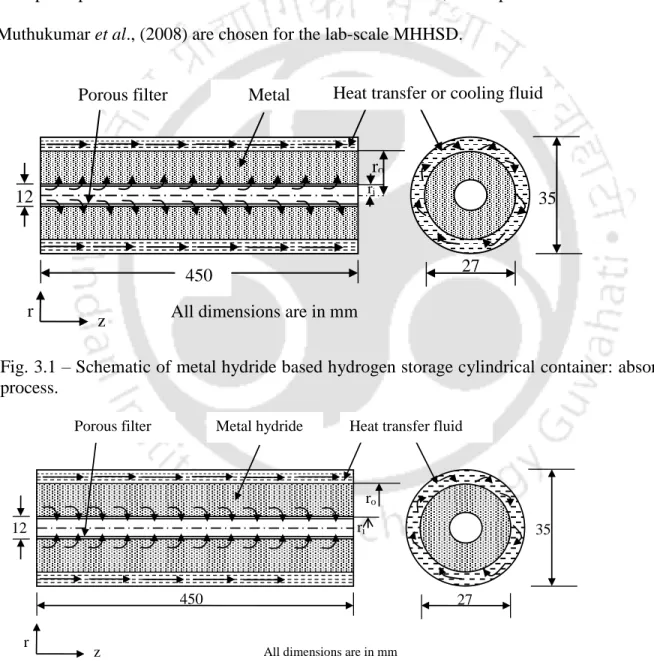
Physical model of lab-scale MHHSD
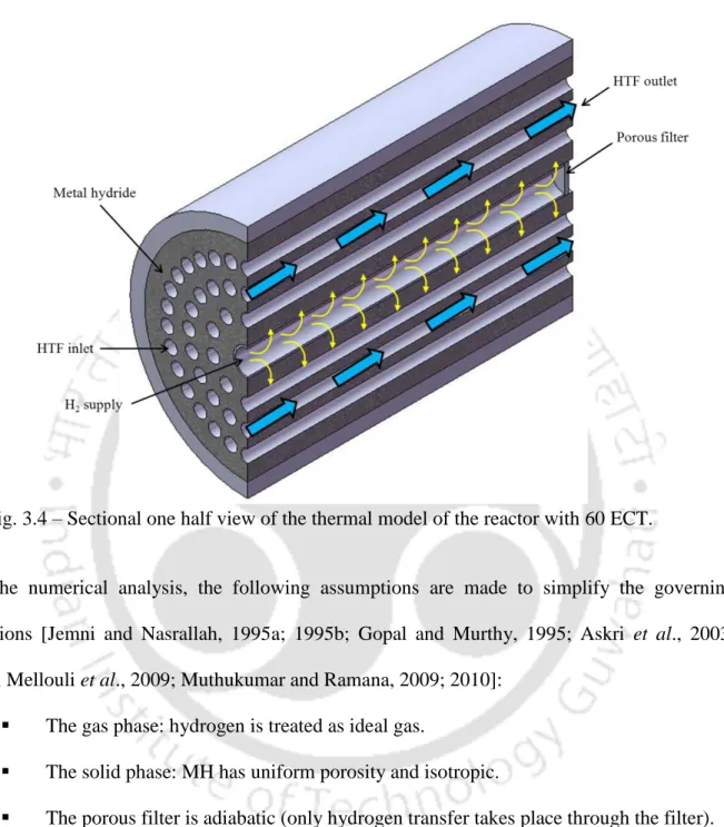
In the hydration (absorption) process, as shown in Figure 3.1, hydrogen flows to the MH bed. The porous filter also prevents the hydride particles from being carried away by the hydrogen gas during the desorption process.
Physical model of MHHSD with ECT
Inside the hydrogen storage container: both the hydrogen and MH are in local thermal equilibrium. The hydrogen storage container is adiabatic (there is no heat transfer between the container and surroundings).
Formulations
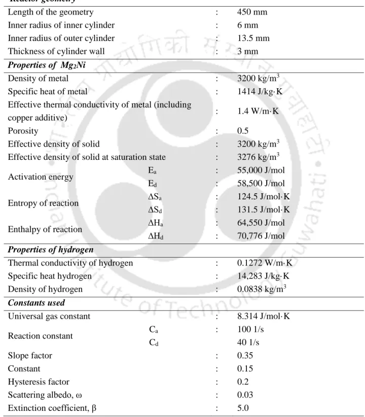
The thermo-physical properties are constant and independent of the hydride bed temperature and other operating parameters. In the energy equation, an effective heat capacity and effective thermal conductivity of the hydride bed is given by. The amount of hydrogen absorbed/desorbed is calculated using the continuity equation involving the density (ideal gas equation) and velocity (Darcy's law) of the hydrogen inside the container.
The hydrogen storage capacity and the amount of desorbed hydrogen (wt%) are calculated from the above equation.
Initial conditions and boundary conditions .1 Lab-scale MHHSD
For MHHSD with ECT, initially (t = 0.0) the hydride bed and hydrogen gas temperature, hydride equilibrium pressure, hydride density, and hydride concentration are assumed to be constant. T is the temperature of the hydride bed at the interface between the hydride bed and the convective wall (the outer radius of the ECT), T is the temperature with the suffixes fi and fo for the inlet and outlet temperature of the HTF, respectively, and mfis the mass flow rate of the HTF.
Solution methodology .1 Lab-scale MHHSD
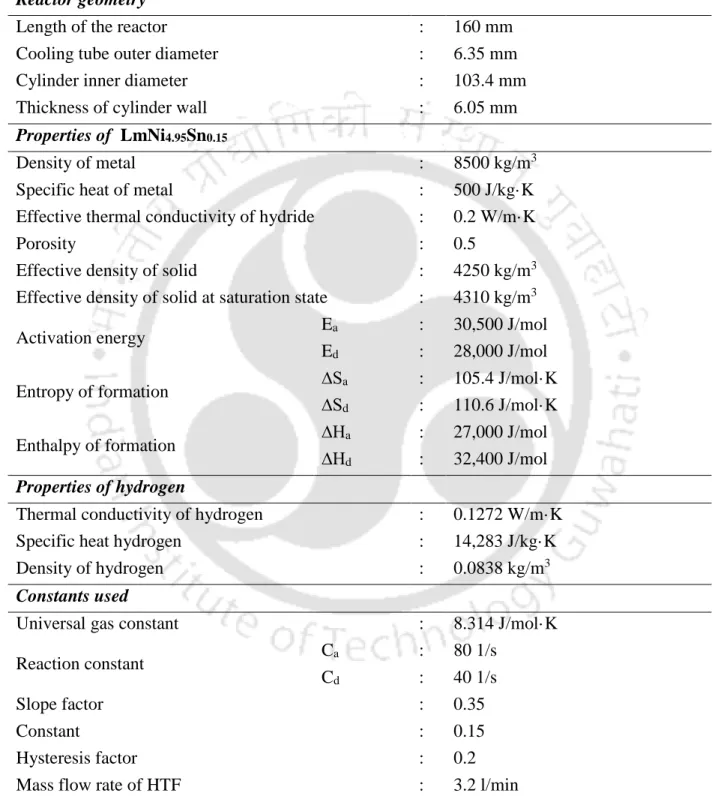
For the reactor dimensions given in Table 3.2, the effect of the size of the control volumes r z on the average bed temperature over time is studied. It effectively solves the energy equation (heat transfer in convection and conduction mode) (Equation 3.1a) and the hydrogen mass (diffusion) (Equation 3.4) and momentum (Darcy's law) (Equation 3.6) in the porous media module. The thermal model formulations for predicting the coupled heat and hydrogen transfer characteristics during hydrogenating and dehydrating processes, initial conditions and boundary conditions are presented separately for both laboratory-scale MHHSD and MHHSD with ECT models.
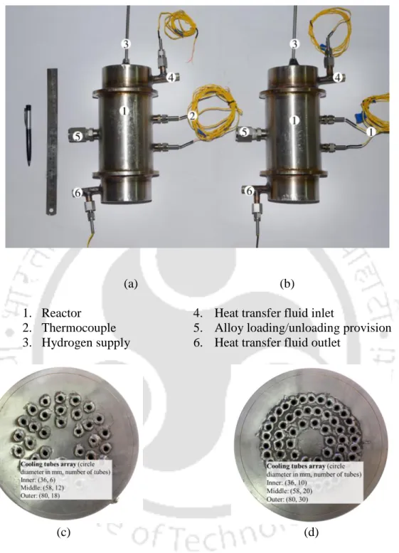
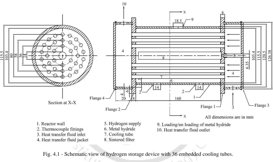
In this chapter, schematic (assembled) and photographic images of the 36 and 60 ECT hydrogen storage reactors, the detailed layout of the test setup and experimental procedure are discussed.
Details of experimental set-up and hydrogen storage reactors
Here, the HTF supplied at one (right) end passes through the ECT to heat/cool the reactor bed and then reaches the other (left) end of the reactor (Figure 4.1). Valves V1, V2, V5 and V7 are closed when there is no significant change in the flow of hydrogen from the reactor. The rate of hydrogen absorption/desorption and the total amount of hydrogen absorbed and desorbed into/out of the reactor are monitored using a Coriolis mass flow meter via a data acquisition system.
Finally, all valves are closed and the reactor is brought to room temperature.
Summary
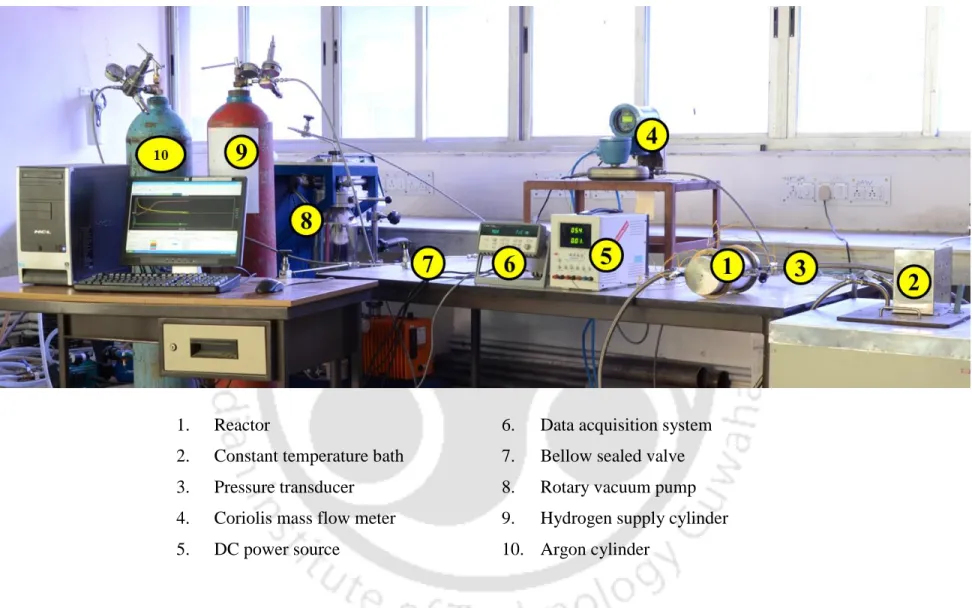
Thermocouples (K-type metal-wrapped thermocouple with an accuracy of ±0.5 °C) are placed at various locations to measure the temperature and also pressure sensors (resistive piezo transducers with an accuracy of ±0.1 bar) are used to measure pressure in different places and these adjustments are shown in Fig. Constant temperature circulating thermostatic oil bath (range 10 – 150 ºC) is used to supply HTF to MHHSD during hydration and dehydration processes. The rotary vacuum pump is used to create vacuum in the experimental setup and also in the MHHSD.
Tests were performed over 200 absorption and desorption cycles and no significant change in the absorption and desorption capacity was reported.
Results and Discussion
Numerical results of lab-scale MHHSD: absorption process
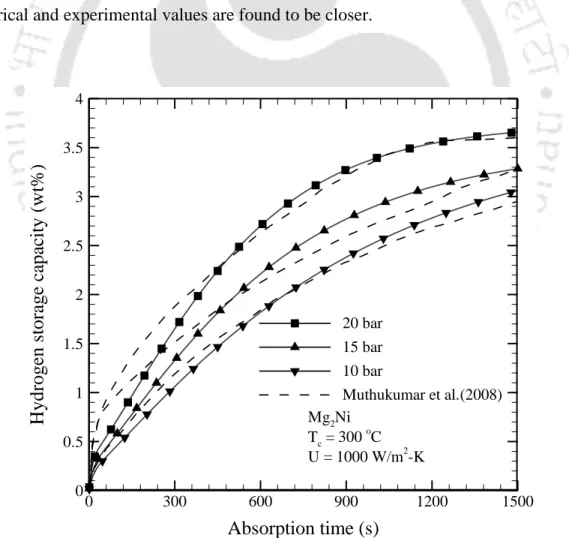
- Validation of numerical model
- Effect of supply pressure
- Effect of radial locations
- Effect of bed thickness
- Effect of bed thermal conductivity
- Effect of cooling fluid temperature
An opposite trend is observed for the time variation of average bed temperature (Fig. 5.5 – Effect of thermal conductivity of the bed on variations of (a) hydrogen storage capacity and (b) average bed temperature. Effect of coolant temperature in Hydrogen storage capacity and the change in average bed temperature are shown in Fig.
5.6 – Effect of coolant temperature on variations of (a) hydrogen storage capacity and (b) average bed temperature.
Numerical results of lab-scale MHHSD: desorption process
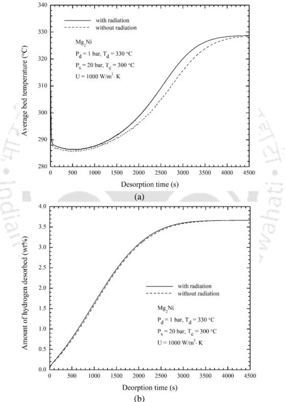
- Effect of radiation heat transfer
- Radial variations of bed temperature and hydrogen concentration
- Effect of heat transfer fluid temperature
- Effect of overall heat transfer coefficient
5.7 – Effect of radiation heat transfer on variations of (a) average bed temperature with and without radiation and (b) amount of desorbed hydrogen. The effects of the temperature of the heat transfer fluid (desorption temperature) on the time variations of the average bed temperature and the amount of hydrogen desorbed are shown in Figs. 5.9 – Effect of heat transfer fluid temperature on variations of (a) average bed temperature and (b) amount of hydrogen desorbed.
The effect of the overall heat transfer coefficient (U) on the variation of the average bed temperature and the amount of desorbed hydrogen is illustrated in Fig.
Numerical results of MHHSD with ECT
- Absorption process
- Desorption process
- Grid independent test
- Comparison between 2-D and 3-D thermal models
- Validation of numerical simulation
- Absorption characteristics .1 Effect of supply pressure
- Effect of (effective) thermal conductivity
- Pictorial representation of hydride bed temperature during absorption process With the absorption condition of 30 bar at 30 °C, the transient behavior of hydride bed
- HTF variations along ECT at different axial locations: absorption process
- Variation in HTF at different radial locations: absorption process
- Desorption characteristics .1 Effect of hot fluid temperature
- Effect of effective thermal conductivity of the hydride bed during desorption process
- Pictorial representation of hydride bed temperature during desorption process At different time intervals of 30, 100, 175, 300, 500 and 1000 s, the pictorial representation
- Variation in HFT along the ECT at different axial locations: desorption process The variations in HFT along the ECT at different axial distances with time are illustrated in
- Variation in HFT at different radial locations: desorption process
The effect of hydrogen supply pressure on the variations of the average hydride bed temperature is shown in Fig. 5.16(b) shows the effect of effective thermal conductivity of the hydride bed on the variation of HSC with absorption time. In general, the average hydride bed temperature decreases with increase in effective thermal conductivity of the hydride bed.
5.16 – Effect of (a) feed pressure and (b) effective thermal conductivity of the hydride layer on hydride rate.
Experimental results of MHHSD: absorption process
- Effect of supply pressure
- Effect of absorption temperature
- Effects of cooling fluid (oil) flow rate
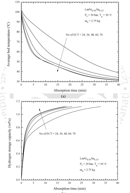
- Effect of number of embedded cooling tubes
- Effect of cooling fluid (water) flow rate
The effect of absorption temperature on the variations of hydrogen absorption rate and average bed temperature with time for 36 and 60 ECT is shown in Fig. 5.28 – Effect of coolant (oil) flow on changes in absorption rate and average. As the HTF flow rate increases, the rate of absorbed hydrogen increases.
5.31(b) illustrates the effect of HTF flow rate on the variations of the amount of hydrogen absorbed.

Experimental results of MHHSD: desorption process
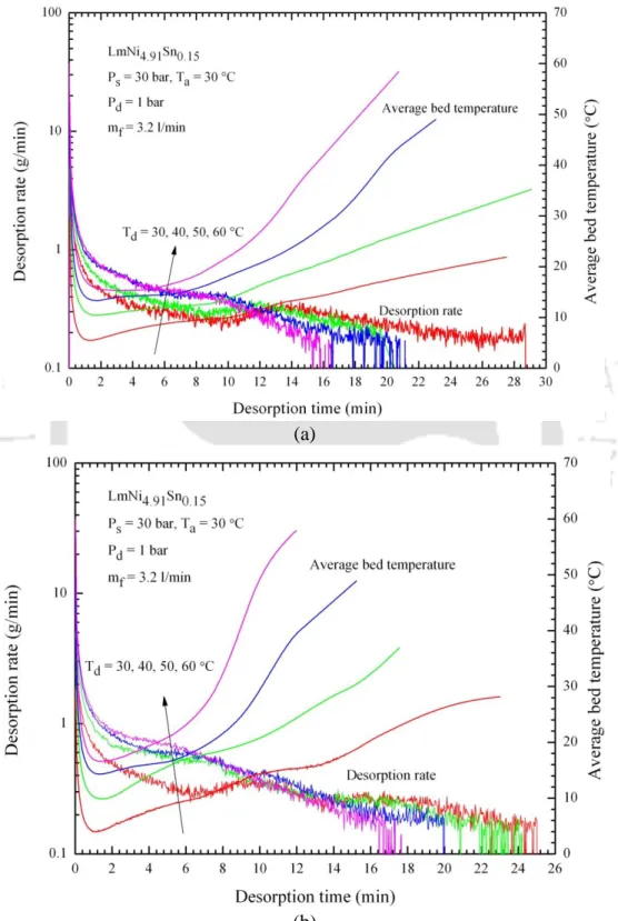
- Effect of desorption temperature
- Effect of hot fluid (oil) flow rate
- Effect of number of embedded cooling tubes
- Effect of hot fluid (water) flow rate
- Pressure drop across the reactors
5.33 – Effect of desorption temperature on the variations of the amount of hydrogen desorbed over time for (a) 36 and (b) 60 embedded cooling tubes. The effect of desorption temperature on the variations of the amount of hydrogen desorbed over time is illustrated in Fig. The effect of HTF flow rate on variations in the amount of hydrogen desorbed is shown in Fig.
5.37 – Effect of hot fluid (water) flow rates on the variations of (a) desorption rate and average bed temperature and (b) amount of hydrogen desorbed.
Summary
Moreover, this chapter also reports the pictorial presentation of the temperature of the hydride bed during the hydration/dehydration process. The effects of feed pressure, absorption temperature, and flow rate of HTF (oil and water) on variations in hydrogen absorption rate, amount of hydrogen absorbed, hydrogen storage capacity, and average bed temperature are reported. Dehydration characteristics are also reported for various desorption temperatures, hot liquid temperatures, and hot liquid flow rates.
From this experimental study, it is observed that the rate of hydrogen absorption/desorption at a given operating condition is fast for the reactor with 60 ECT.
Conclusions and Future Scope
Numerical studies
- Lab-scale metal hydride based hydrogen storage device (MHHSD)
- Metal hydride based hydrogen storage device (MHHSD) with embedded cooling tubes (ECT)
The effects of inlet pressure, layer thickness, effective layer thermal conductivity, and coolant on hydrogen storage capacity and average layer temperature were studied. At different supply pressures, the hydrogen storage capacities were compared with experimental results available in the literature. This study was extended to a 3-D mathematical model using 2.75 kg hydrogen storage vessels based on LmNi4.91Sn0.15 with 60 ECT, and their hydriding and dehydrating properties were predicted at different hydrogen supply pressures (10 – 35 bar), different hot liquid temperatures (30 – 60 °C) and effective thermal conductivity of the hydride layer W/m·K).
The variations in hydrogen storage capacity (wt%) and the amount of adsorbed hydrogen (wt%) were reported for different supply pressures and hot fluid temperatures.
Experimental studies of hydrogen storage performance of MHHSD with ECT
- Absorption process
- Desorption process
In the reactor with 60 ECT, at 60 °C desorption temperature and 3.2 l/min oil flow rate, the desorption rate of hydrogen was found to be fast. With the same reactor configuration (60 ECT), water as heat transfer fluid at a flow rate of 30 l/min and at 50 °C, the maximum amount of hydrogen was desorbed. The desorption time was reduced by 46.7% when the water flow rate was increased from 5 l/min to 30 l/min.
For a given flow rate, the 36 ECT reactor had more pressure drop compared to the 60 ECT reactor.
Scope of future work
The reason for higher pressure drop in the reactor with 36 ECT was more flow resistance and higher flow velocity.
Numerical simulation of heat and mass transfer in metal hydride hydrogen storage tanks for fuel cell vehicles, Int J Hydrogen Energy. Numerical investigation of coupled heat and mass transfer during desorption of hydrogen in metal hydride beds. Numerical simulation of coupled heat and mass transfer in metal hydride-based hydrogen storage reactor.
Numerical analysis of heat and mass transfer during absorption of hydrogen in metal hydride based hydrogen storage tanks.
Appendix A
Discretization of Governing Equations