Arnold, MD, FACS Professor of Neurosurgery Department of Neurosurgery University of Kansas Medical Center Kansas City, Kansas. Mandigo, MD Instructor of Clinical Neurosurgery Department of Neurological Surgery Columbia University College of Physicians.
BEST EVIDENCE FOR SPINE SURGERY
Accordingly, the chapters have been designed to present decision-making based on the available evidence regarding two competing treatment options for a single disease. Undoubtedly, both neurosurgery and orthopedics make significant contributions to the craft of spine surgery, and the collection of senior authors featured in Best Evidence for Spine Surgery includes, in our opinion, many of the best.
Cervical Diskectomy and Fusion Versus Arthroplasty
SURGICAL OPTIONS
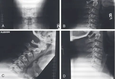
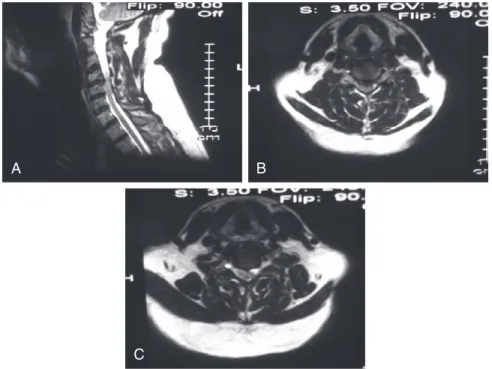
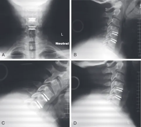
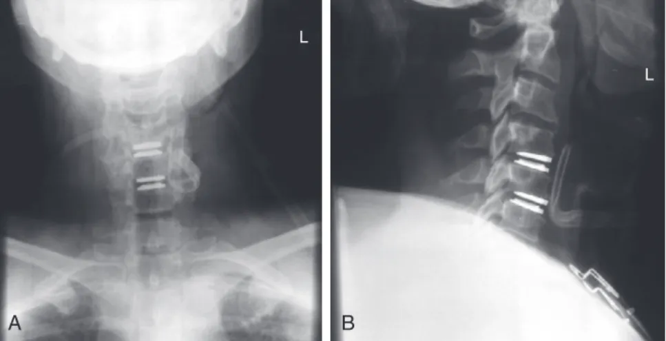
The Food and Drug Administration (FDA) study of two-level cervical disc arthroplasties was ongoing, and the patient was interested in participating in this study at the authors' institution. All appropriate consents were obtained according to study protocols, and the patient was scheduled for two-level cervical disc replacement at C4-5 and C5-6.
FUNDAMENTAL TECHNIQUE
If removal of the PLL or central osteophytes is required to achieve neural decompression, this should be performed. Most studies have specific rotational specifications that require strict centering of the implant on the midline.
DISCUSSION OF BEST EVIDENCE
-year follow-up results suggest that cervical disc replacement is a viable alternative to ACDF in patients with persistently symptomatic, single-stage cervical disc disease. IDE trials included patients undergoing single-stage cervical disc replacement for isolated disc disease.
COMMENTARY
Mummaneni PV, Burkus JK, Haid RW, et al: Clinical and radiographic analysis of cervical disc replacement compared with allograft fusion: a randomized controlled clinical trial, J Neurosurg Spine. Heller JG, Sasso RC, Papadopoulos SM, et al: Comparison of Bryan cervical disc replacement with anterior cervical decompression and fusion: clinical and radiographic results of a randomized, controlled, clinical trial, Spine.
Diskectomy and Fusion
Bone-Grafting Options
Master Tips 2-1 • Make sure most of the neurologic compression occurs ventral to the sacrum and is at the level of the disc space. Each disk space should be resized prior to placement of the root fusion device so that the most appropriate size can be selected (Figure 2-6).
DISCUSSION OF BEST EVIDENCE Autogenous Bone Grafts
Allogeneic Bone Grafts
Synthetic Interbody Spacers
Recombinant Human Bone Morphogenetic Protein-2
Need for Posterior Fusion
Emery SE, Fisher JR, Bohlman HH: Three-level anterior cervical discectomy and fusion: radiographic and clinical results, Spine. Wang JC, McDonough PW, Endow KK, et al: Increased fusion rates with cervical plating for two-level anterior cervical discectomy and fusion, Spine.
Longitudinal Ligament: Anterior Versus Posterior Approach
Anterior surgical options include multilevel anterior cervical discectomy and fusion (ACDF) or multilevel anterior cervical corpectomy and fusion (ACCF). In certain cases, peripheral treatment is necessary, combining anterior decompression and fusion with supplementary posterior instrumented fusion.
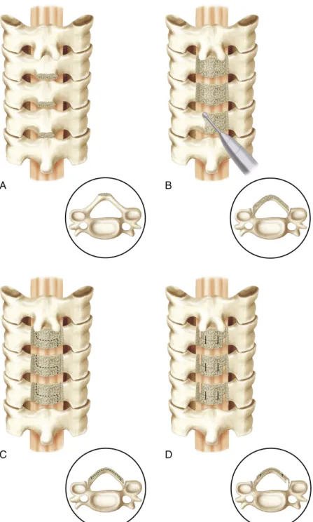
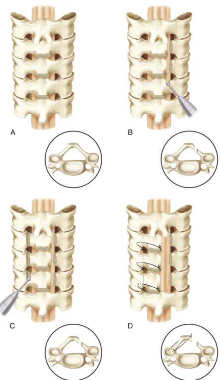
Multilevel Cervical Diskectomies and/or Corpectomies
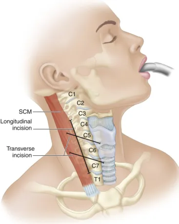
The dissection is performed bluntly, anteriorly and medially from the front edge of the sternocleidomastoid, through the deep cervical fascia, where the omohyoid is encountered. The middle layer of the deep cervical fascia between the omohyoid and sternocleidomastoid is cut bluntly.
Laminectomy with or without Fusion
After the decompression is complete, the focus shifts to the reconstruction and transplantation of the corpectomy defect. Masters Tips 3–5 • If unilateral vertebral artery injury occurs while drilling or tapping the lateral screw holes, fill the hole with bone wax and place the hemostasis screw and do not instrument on the contralateral side.
Laminoplasty
Iwasaki M, Okuda S, Miyauchi A, et al: Surgical strategy for cervical myelopathy due to ossification of the posterior longitudinal ligament. Iwasaki M, Okuda S, Miyauchi A, et al: Surgical strategy for cervical myelopathy due to ossification of the posterior longitudinal ligament.
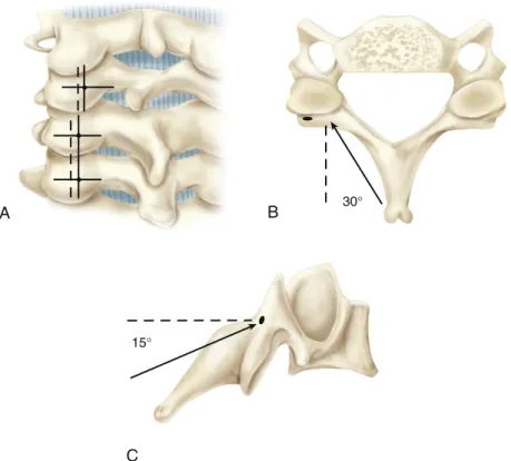
MINIMALLY INVASIVE SURGICAL OPTIONS Transfacet Approach
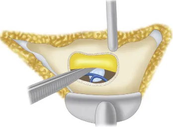
Soft lateral, contiguous hernias that extend beyond the edge of the thecal sac are the ideal indication for this approach. Tips from Masters 4-2 • Transfacet approaches are best suited for lateral and preferably soft hernias that can be removed with minimal manipulation of the thecal sac.
Thoracoscopic Approach
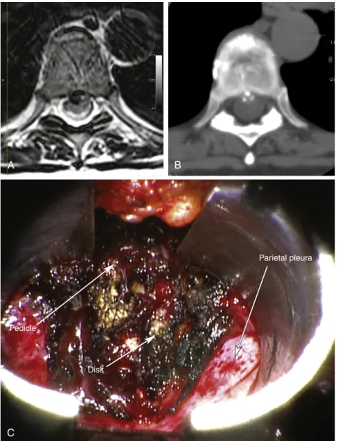
Minimally Invasive Retropleural Approach
The parietal pleura over the T8 rib head, the T7-8 disc space, and the lateral aspect of the T8 vertebral body were mobilized and reflected ventrally. The rib head was removed with a drill and burr that exposed the disc space.
Neurologic Deficit: Microdiskectomy Versus Conservative Treatment
The results of the motor examination were 5/5 in bilateral upper and lower extremities, with very mild weakness of dorsiflexion on the right. The patient had a slightly decreased sensation of pricking on the back of the right foot; otherwise his sensation was intact.
TREATMENT OPTIONS
He was mildly tender on palpation of the lower lumbar spine and had a positive result on the straight leg raise test on the right. The patient was seen in the clinic for follow-up 2 weeks later and was doing well, with significant improvement in pain in the lower back and right radicular leg.
Conservative Treatment
Opioids and muscle relaxants are often used to treat patients with acute radiculopathy when their pain is severe and inadequately controlled by non-opioid analgesics. When prescribed, opioids should be used on a fixed schedule for a limited time and should not be combined with muscle relaxants due to the additive sedative effects.
Surgical Treatment
The nerve root may be displaced medially or laterally, depending on the size and location of the herniated disc, but this is necessary. Lumbar radiculopathy remains one of the most common and challenging causes of disability in the Western world.
ACKNOWLEDGMENT
Peul WC, van den Hout WB, Brand R, et al: Leiden-The Hague Spine Intervention Prognostic Study Group: Prolonged conservative care versus early surgery in patients with sciatica caused by lumbar disc herniation: two-year results of a randomized controlled trial, BMJ. Arts MP, Brand R, van den Akker ME, et al: Leiden-The Hague Spine Intervention Group Prognostic Study (SIPS): Tubular discectomy versus conventional microdiscectomy for sciatica: a randomized controlled trial, JAMA.
Stenosis: Laminoplasty Versus Laminectomy and Fusion
Anterior approaches to the cervical spine are generally preferred in patients who have cervical myelopathy due to soft disc herniation or spondylotic degeneration limited to the disc level, or who have a kyphotic deformity of the cervical spine.1 ,2 Methods include anterior cervical diskectomy and fusion, and corpectomy plus strut-cage fusion, usually using anterior instrumentation. Patients who have contraindications to anterior cervical approaches (such as some patients with ossification of the posterior longitudinal ligament [OPLL] with dural penetration) and patients with a spinal cord lesion that is diffuse or more dorsal due to buckling of the ligamentum flavum , are often treated using posterior procedures.2 Patients with preserved cervical lordosis are suitable candidates for a posterior approach.
Laminectomy
The extended open-door laminoplasty was described by Hirayabashi and colleagues.20 A high-speed drill is used to drill down to the ligamentum flavum on one side of the exposed lamina. Several variations of the open-door laminoplasty rely on instrumentation for internal fixation of the mobilized laminae (Figure 6-6).
Skip Laminectomy
Miyazaki K, Kirita Y: Extensive simultaneous multi-segment laminectomy for myelopathy due to the ossification of the posterior longitudinal ligament in the cervical region, spinal column. A retrospective review showing good results with multilevel laminectomy in patients with cervical myelopathy due to ossification of the posterior longitudinal ligament.
Fusion Versus Artificial Disk
The integrity of the left L4-5 facet joint was preserved after the initial laminectomy and diskectomy were performed five years earlier. The common denominator of each option is the removal of the pain generator – the diseased intervertebral disc.
Anterior Lumbar Diskectomy and Interbody Fusion
Far Lateral or Trans-Psoas Approach
This creates a very small safe operative window (as small as 13% of the disc space) for the trans-psoas approach at the L4-5 level. Tips from the Masters 7-2 • The direct lateral approach is more difficult and carries a higher risk of neurovascular complications at the L4-5 level than at more cephalad levels.
Posterior Fusion (Transforaminal or Posterior Lumbar Interbody Fusion)
Total Disk Replacement
Patient Positioning
Once the peritoneum has been successfully mobilized, the vascular structures should be carefully dissected from the left anterolateral side of the spine to the right. There is often inflammatory tissue in front of the disc, which makes it difficult to mobilize the vascular structures.
Identification of the Midline
Diskectomy and End-Plate Preparation
Remobilization
Tips from the Masters 7-3 • Midline determination is vital for subsequent testing and implantation of the TDR prosthesis. Tips from Masters 7-5 • Remobilization is an important step in the procedure and directly affects the function of the TDR device.
Trialing
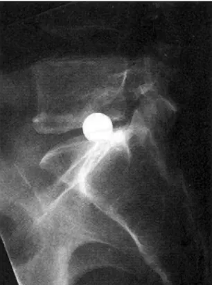
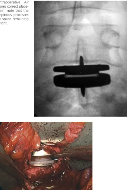
Care must be taken to insert the distractors properly, placing them as far posteriorly in the disc space as possible, resting on the cortical ring, to avoid perforation of the endplate (Figure 7-16). Once a trial implant of the appropriate size is placed, an AP image is taken to verify the position of the implant in the midline (Figure 7-17).
Device Preparation
If the trial implant is translated off-center, further discectomy or annulotomy may be required to balance the disc and allow the implant to be centered.
Device Insertion
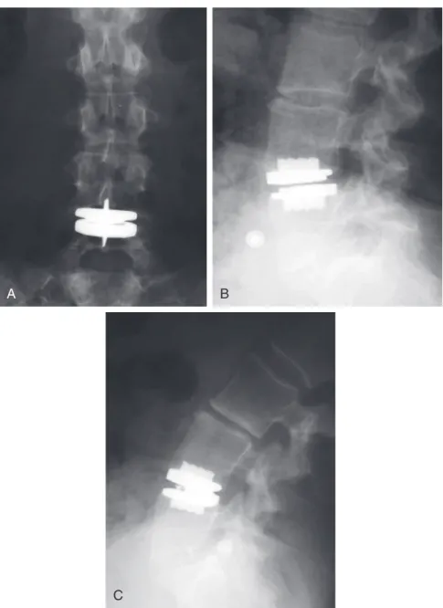
Final AP fluoroscopic images should be obtained to verify the position of the prosthesis in the center of the disc space, using the appropriate anatomic landmarks previously described (Figure 7-18). Note that for this particular semi-clamped device, there is no gap or separation at the intersection of the polyethylene and the lower end plate of the device.
Operative versus Nonoperative Treatment
In the journal Spine, approximately 16% of published studies are considered to provide the highest level of evidence. The FDA IDE studies of arthroplasty versus fusion fit the relevant criteria for a Level I study.
Disk Replacement versus Fusion
Adjacent-Level Disease
These in vitro findings have yet to be clinically validated in a Level I study; however, when the rate of adjacent-level disease found in David's TDR study (2.8%)35 is compared with the historical rate of adjacent disease in the patient undergoing fusion (36% at 10-year follow-up),42 there is an obvious demonstrable clinical benefit of the TDR procedure in reducing degenerative changes at the adjacent level. In the European long-term studies35, there was a 4.7% rate of device-related complications, with three cases of subsidence and two cases of nuclear subluxation.
Financial Considerations
At the 24-month follow-up, a significantly greater proportion of patients in the TDR group than in the fusion group were satisfied with the outcome (P < .05). There was significantly less decrease in the TDR group than in the fusion group ( P < .05).
Tips from Masters 8-1 • Preoperatively look for an area of high intensity within the facet joint complex on axial T1-weighted MRI images.
TREATMENT OPTIONS Observation
Laminectomy Decompression at L3 through L5
Decompression and Fusion without Instrumentation
Decompression and Fusion with Instrumentation
In the most recent of several retrospective studies, Ghogawala and associates11 looked at outcomes for 20 patients undergoing laminectomy and 14 who underwent laminectomy. Scores on the Short Form 36 (SF-36) Health Survey also showed improved functional outcome in the patients undergoing decompression and fusion.
Schwannoma: Surgery Versus Radiosurgery Versus Observation
MANAGEMENT CONSIDERATIONS
In the patient described here, the tumor is relatively small, is not associated with any significant mass effect and lies below the level of the spinal cord. Based on the lateral location, the origin of the nerve root is most likely L4 or L5 due to the somatotopic organization of the cauda equina.
SURGICAL CONSIDERATIONS
First, as with nonoperative treatment, no tissue is obtained to verify the histological characteristics of the tumor. Motor weakness occurred in approximately 10% to 33% of patients in whom a section of the affected nerve in functional nerve roots (C5 through T1 and L1 through S1) was transected. The mechanism of this phenomenon is unclear.
Posterior Approach
Although this sheath may allow anatomical preservation of the corresponding motor root for intradural sensory root tumors, or vice versa, sacrifice of the entire motor and sensory root is required if the tumor extends through the root sleeve, distal to the dorsal root ganglion17. Tips from the Masters 9-1). The paired root can be firmly applied to the surface of the tumor capsule but can be safely dissected from the tumor surface, especially at the critical cervical (C5 to C8) and lumbosacral (L2 to S1) levels.
Posterolateral Approach
Presumably, the gradual functional denervation of the involved nerve root allows reinnervation to occur through sprouting at the anterior horn cell or endplate level of the muscle. The delicate intradural nerve bundles of the entire motor or sensory root of tumor origin usually disappear into the substance of the tumor, because they do not have a well-developed interfascicular connective tissue matrix.
Anterolateral Approach
This approach can provide exposure of intradural structures as well as extensive access to the anterior and posterior paraspinal region, ventral spinal canal, and vertebral body. aid of an operative microscope. Tumors with intradural and extradural components may require a T-shaped dural opening, with one limb adjacent to the nerve root sleeve.
FUNDAMENTAL TECHNIQUE Surgical Technique—Posterior
Cervical Spine—Posterolateral
If nerve root sacrifice is required or has already been performed, the lateral dural incision should extend around the dural root sleeve to detach it from the dural tube. Dissection of this plane may be bloody because of the extensive venous plexus surrounding the nerve root and vertebral artery.
Thoracolumbar Spine—Posterolateral
The midline portion of the incision is continued down through the subcutaneous tissue to the spinous processes. Instead, the midline incision is continued only to the tip of the spinous processes.
Posterior Fusion
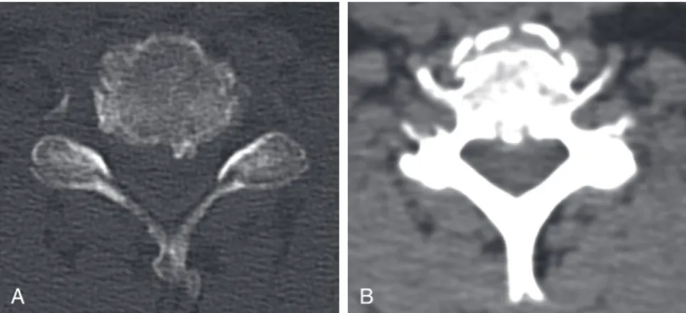
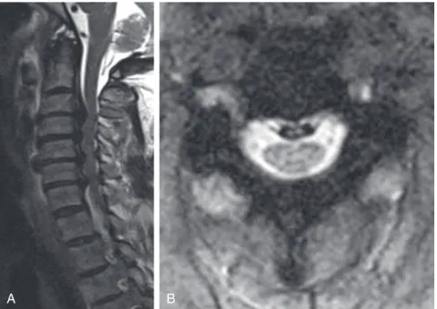
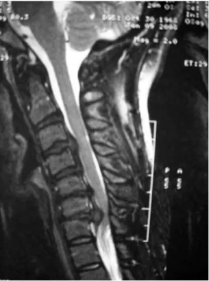
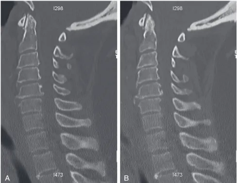
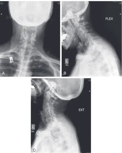
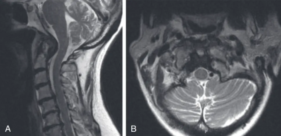
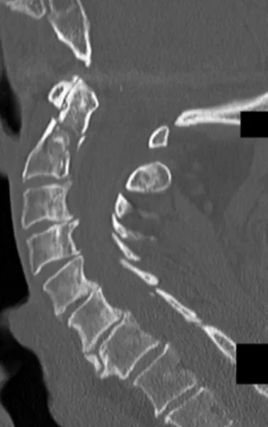
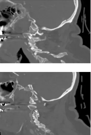
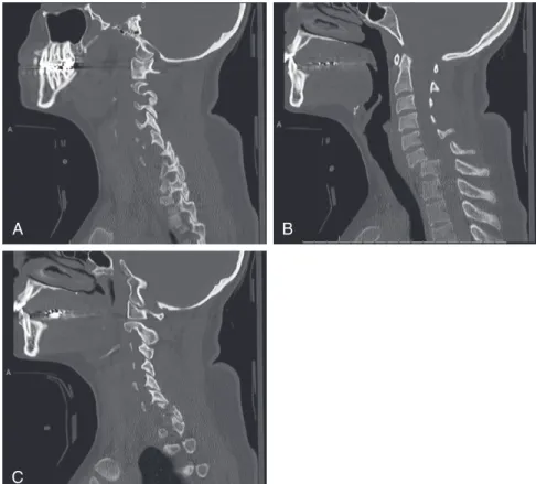
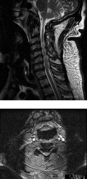
Imaging: An MRI scan of the cervical spine revealed a pannus at the C1-2 joint leading to a distortion of the anterior thecal sac (Figure 10-1). CT images of the cervical spine revealed the presence of an old type II odontoid fracture, the anterior tubercle of the C1 fracture, and calcified pannus around the C1-2 joint (Figure 10-2).
SURGICAL OPTIONS AND FUNDAMENTAL TECHNIQUES Transoral-Transpharyngeal Decompression Plus Posterior
Unfortunately, this maneuver may be associated with a CSF (cerebrospinal fluid) leak, and the anterior dura may be extremely difficult to repair primarily. Dural grafts can be used with fibrin glues in conjunction with lumbar drainage to aid in healing.
Transcervical Decompression Plus Posterior Stabilization (Transcervical Endoscopic Odontoidectomy)
Specifically, the ability to visualize the inferior and middle clivus is limited by the transoral approach, and a complete soft palate split, hard palate split, or extended maxillotomy may be required. Such procedures can increase operating time, prolong recovery, and increase patient morbidity, so a 30-degree endoscope can be used to avoid these additional procedures.3.
Posterior Fixation Alone
For this reason, the patient must also be clearly warned about the potential approach-related morbidity. This article highlights some of the ways in which he reviews and approaches such complex problems at the craniocervical junction.
Odontoid Screws Versus Posterior Fusion
Surgical management options for a type II odontoid fracture can be divided into two subgroups: anterior approach and fixation with the goal of direct osteosynthesis, and posterior approach and fusion of the C1-C2 complex.
Anterior Odontoid Screw
In addition, the transverse ligament should be carefully assessed for injury, because injury to this ligament is a contraindication to anterior odontoid screw fixation. Direct comparison of results for anterior odontoid screw fixation and posterior C1-C2 fusion in a retrospective review including an elderly cohort suggested better overall results with the posterior procedure when degree of fusion and rate were considered. of reoperation.14 A retrospective study of data on a cohort of elderly patients undergoing surgery for acute type II odontoid fractures found a significantly higher incidence of postoperative pneumonia, dysphagia, and vocal cord problems in patients who underwent anterior screw fixation (compared to those treated using different posterior techniques).1 In patients with good bone quality and appropriate fracture orientation, anterior odontoid screw fixation has been demonstrated to be associated with a rate of fusion of approximately 90%, but the use of the technique in the elderly and/or patients with osteoporosis remains controversial.
Posterior C1-C2 Fusion
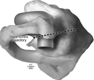
Master Tips 11-4 • The lower surface of the C1 ring may need to be scored to correctly measure the C1 side mass. The starting point is proximal to the C2-3 facet and should be confirmed by palpation of the medial border of the isthmus and by preoperative imaging.
Nonoperative Management
With proper dimensions, the fit should be tight - compressive force is necessary to promote adequate fusion. Patient-specific issues should be considered in determining the duration of cervical orthosis use.
Surgical Management
Borm W, Kast E, Richter HP, et al. Anterior screw fixation in tooth fractures type II: is there a difference in outcome between age groups. An analysis of data for 33 patients with type II dental fractures treated with halo-vest immobilization.
Versus Harms/Melcher Procedure
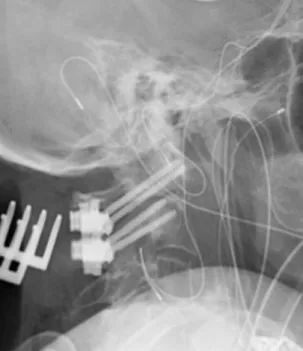
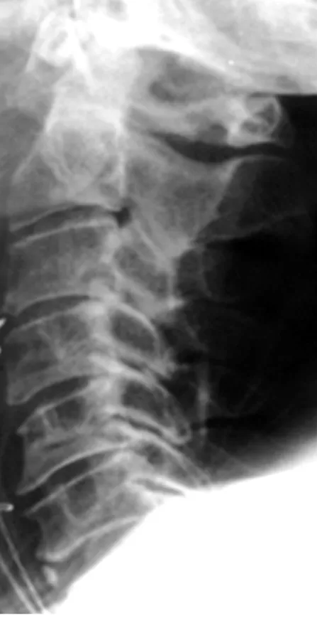
There was posterior subluxation of the left lateral mass of C1, associated with a mildly displaced intra-articular fracture of the lateral mass (Figure 12-2). Such radiographs were not taken before placement of the dental screw, but based on its apparent displacement.
Transarticular Screw Fixation
Studies have shown a lower rate of union (70% to 88%) and a higher rate of complications in the elderly with this procedure.15,16 In addition, there was a C1 lateral mass fracture and rotator C1-C2 subluxation in this case. they are signs of instability and predict a bad outcome. Another limitation of the technique is that spinal misalignment must be reduced prior to screw placement.

Posterior C1-C2 Fusion with Polyaxial Screw and Rod Fixation
FUNDAMENTAL TECHNIQUE Transarticular Screw Technique
A careful subperiosteal dissection of the C1 arch and C2 lamina was performed and self-retaining retractors were inserted. Once the trajectory is determined, small vertical knife incisions are made in the upper thoracic spine (around T2) to allow proper placement of the trocar along the correct trajectory.
Technique of C1-C2 Fusion Using a Screw and Rod Construct
The entry point should be in the cranial and medial quadrant of the isthmus surface of C2.3. The drill tip should be directed 5 to 10 degrees medially and parallel to the plane of the pedicle analog of C1.
Fusion Rate
Biomechanical Stability
Melcher and colleagues8 completed biomechanical testing on cadaveric spinal column specimens and found that transarticular screws and screw rod constructs had equivalent biomechanical properties.
Anatomic Characteristics
Madawi AA, Casey AT, Solanki GA, et al: Radiologic and anatomic evaluation of the atlantoaxial transarticular screw fixation technique, J Neurosurg. Dong Y, Hong MX, Jianyi L, et al: Quantitative anatomy of the lateral mass of the atlas, Spine 28:.
Anterior-Only Versus
Circumferential Instrumentation
Retrospective review of failure rates in patients undergoing two- and three-level corpectomies and anterior plate fixation. Biomechanical study showing that hybrid decompression fixation provides better stability than three-level corpectomy and anterior plate fixation.
Incomplete Neurologic Deficit
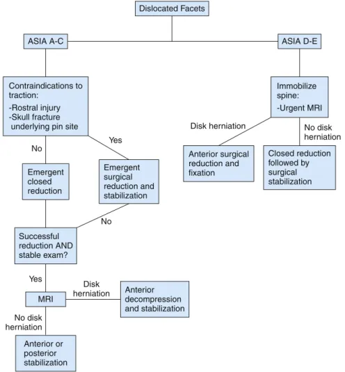
Closed Reduction Versus Urgent Surgery
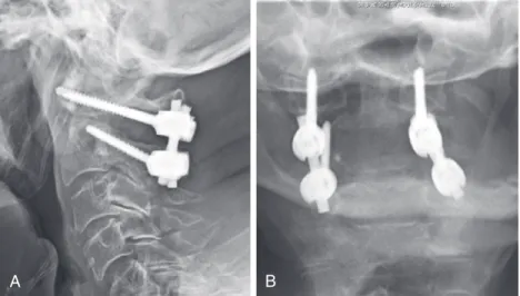
The patient was then taken to the operating room for a C6 corpectomy with anterior fusion of C5-C7, followed by posterior fixation of C5 to C7 on the right side (Figure 14-4). Cranial tongue traction was immediately applied and reduction was achieved at a 40 lb traction weight within 20 minutes of the patient entering the emergency situation.
Closed Reduction
Surgical Reduction
FUNDAMENTAL TECHNIQUE Reduction with Tong Traction
If there is a disc herniation behind the displaced vertebral body, an anterior discectomy should be performed before reduction. In the case of unilateral dislocation, manual traction can be applied with rotation in the direction of the sprained face.
Open Reduction
Grant and colleagues report on a large retrospective study of the usefulness of closed reduction in the treatment of cervical spine injuries. Mahale YJ, Silver JR, Henderson NJ: Neurological complications of cervical spine dislocation reduction, J Bone Joint Surg Br.
Cervicothoracic Junction: Fusion Versus Nonfusion
Superior and inferior borders are the facet joints, and medial and lateral borders of the lateral mass serve as the other borders. The ideal starting point is 1 mm medial to the center of the imaginary X. Van Chen MY, Duenas MJ, Jandial R: Procedure 62: Lateral mass fixation.
Would Standalone Laminectomy Have Been Appropriate?
Uninstrumented laminectomy of the CTJ is usually insufficient due to the unique biomechanical forces present in this area. Almost any subsequent proceeding involving the CTJ must be followed by the CTJ's joinder.”14.
Was There a Place for Laminoplasty in This Case?
Recently, Komagata and colleagues 19 retrospectively reviewed data from 13 patients who underwent open-door laminoplasty for OPLL spanning the CTJ. Several authors offer some modifications (e.g., myoarchitectonic spinolaminoplasty) that prevent disruption of these elements, but long-term outcomes involving the CTJ have not been rigorously examined.4.
Should the Instrumentation Have Been Longer Initially? If So, How Far Caudally? What Type of Instrumention Should Have
More importantly, as shown by Houten and Cooper, fusion with a lateral mass sheath prevented the development of spinal deformity associated with laminoplasty or uninstrumented CTJ laminectomy.16. Regarding the patient in the case presentation, the length of the fusion above the CTJ may need to be adjusted below as well.
Would Intraoperative Navigation (3D Systems Rather Than 2D Fluoroscopy) Have Been Helpful in This Case?
Amaral SH, Silva MN, Giraldi M, et al: Multiple cervical arcocristectomies for the treatment of cervical spondylotic myelopathy: surgical technique and results, J Neurosurg Spine. Saruhashi Y, Hukuda S, Katsuura A, et al: A long-term follow-up study of cervical spondylotic myelopathy treated by "French window" laminoplasty, J Spinal Disord.