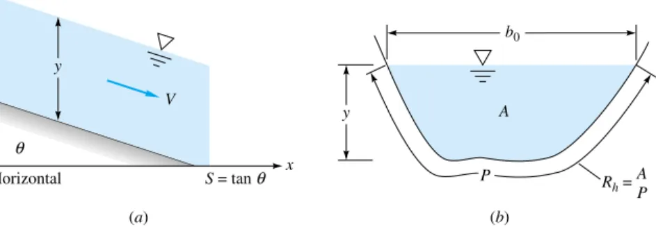
It helps because the pressure along the free surface can be constant, which is therefore equivalent to the hydraulic gradient line (HGL) of the flow. The wetted extent P (see Figure 10.2b) includes the sides and bottom of the channel, but not the free surface and certainly not the parts of the sides above the water level. Although the Moody chart (Figure 6.13) would give a good estimate of the friction factor in channel flow, it is rarely used in practice.
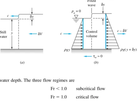
The most common method of classifying open channel currents is by the rate of change in free surface depth. An excellent discussion of the different regimes of open channel flow is given in Ref.
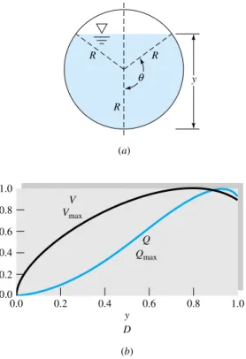
Uniform Flow in a Partly Full Circular Pipe
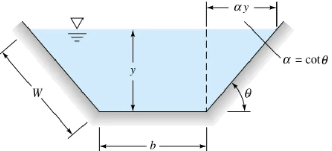
Efficient Uniform-Flow Channels
10.21) Q max 2.129
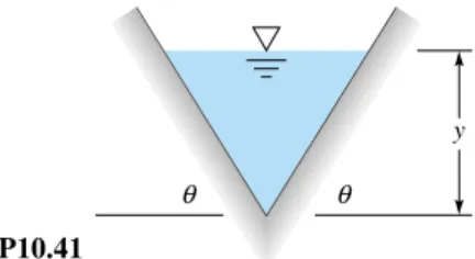
Best Trapezoid Angle
There is no general solution for arbitrary cross sections, but an analysis of the trape- zoid section will show the basic results
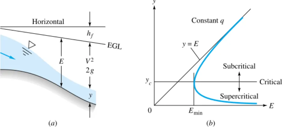
- Specific Energy;
Critical Depth
For a given flow rate, two states are usually possible for the same specific energy. The depth yc corresponds to a channel velocity equal to the shallow water wave propagation velocity C0 from Eq.
10.32) By comparison it follows that the critical channel velocity is
Rectangular Channels
Nonrectangular Channels
Critical Uniform Flow
The Critical Slope
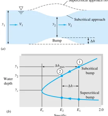
Frictionless Flow over a Bump
Eliminating V 2 between these two gives a cubic polynomial equation for the water depth y 2 over the bump
Estimate (a) the water depth y2 above the hump and (b) the impingement height that will cause the crest flow to be critical. For subcritical approach flow, if it is not too large, we expect a depression in the water level above the hump and a higher subcritical Froude number at the crest.
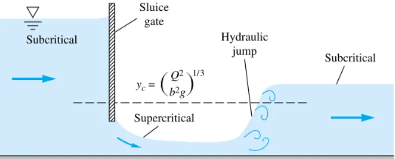
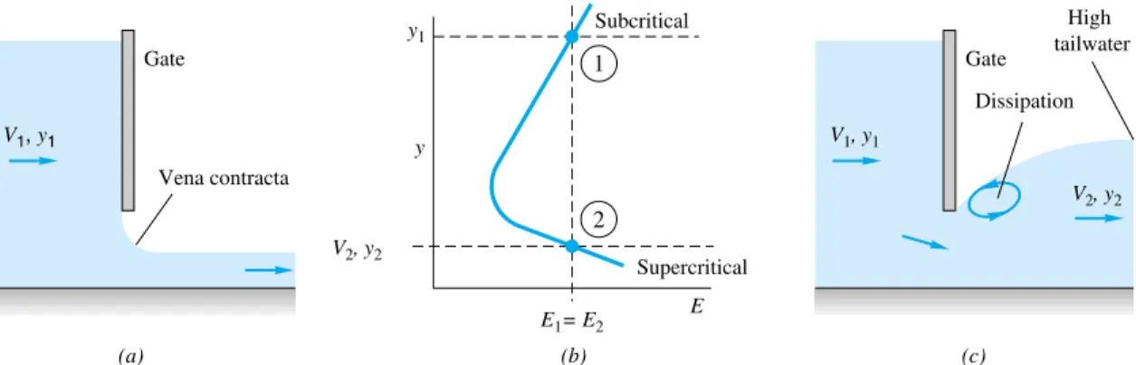
Flow under a Sluice Gate
- If H is the height of the gate gap and b is the gap width into the paper, we can approximate the flow rate by orifice theory
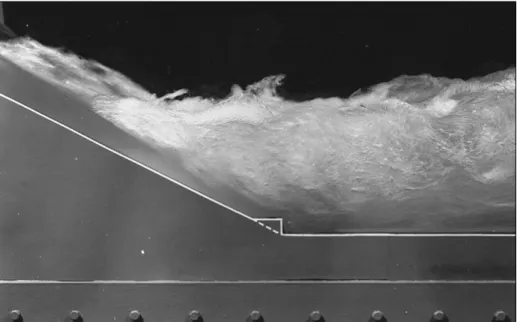
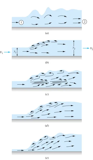
- The Hydraulic Jump
- 1.0: Jump impossible, violates second law of thermodynamics
- 1.7 to 2.5: Smooth surface rise with small rollers, known as a weak jump;
- to 15 percent
- 2.5 to 4.5: Unstable, oscillating jump; each irregular pulsation creates a large wave which can travel downstream for miles, damaging
- to 70 percent
- Gradually Varied Flow 3
In open-channel flow, a supercritical flow can quickly turn into a subcritical flow by passing through a hydraulic jump, as in Fig. the wave of Fig. Unlike the normal infinitely thin shock, the hydraulic jump is quite thick, ranging in length from 4 to 6 times the downstream depth y2[16].
Being extremely turbulent and agitated, the hydraulic jump is a very effective energy dissipater and is a feature of still basin and wastewater applications [16]. Classification The primary parameter affecting hydraulic jump performance is the upstream Froude number Fr1V1/(gy1)1/2. Fr14.5 to 9.0: Stable, well-balanced, steady jump; best performance and action, insensitive to downstream conditions.
A jump that takes place on a steep channel slope can be affected by the difference in water weight components along the current. However, the effect is small, so that classical theory assumes that the jump takes place on a horizontal bottom. Equation (10.9) is therefore the correct solution for a jump if we interpret C and y in Figure 2.
By introducing the Froude number Fr1V1/(gy1)1/2 and solving this quadratic equation for , we get. Finally, we can evaluate the dissipation head loss across the jump from the steady-flow energy equation. Equation (10.45) shows that the dissipation loss is only positive if y2y1, which is a requirement of the second law of thermodynamics.
Basic Differential Equation
Slowly changing bottom slope
Slowly changing water depth (no hydraulic jumps) 3. Slowly changing cross section
One-dimensional velocity distribution
Pressure distribution approximately hydrostatic
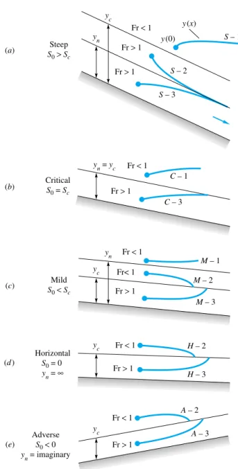
Classification of Solutions
The numbers 1, 2, 3 relate to the position of the starting point on the solution curve relative to the normal depth yn and the critical depth yc. For type 1 solutions, the starting point is above both ynand yc, and in all cases the water depth solution y(x) becomes even deeper and farther away from ynand yc. For type 2 solutions, the initial point is between yn and yc, and if there is no change in the S0of roughness, the solution tends asymptotically to the lowest of ynor yc.
In type 3 cases, the starting point lies below both yn and yc, and the solution curve tends asymptotically towards the lower of these. The basic relation for gradually varied flow, Eq. 10.49), is a first-order ordinary differential equation that can easily be solved numerically. It is assumed that the bottom slope S0(x) and the cross-sectional shape parameters (b0, P, A) are known everywhere along the channel.
The x step sizes can be chosen so that any y variation is limited to no more than, say, 1 percent. Solution curves are generally well behaved if there are no discontinuous changes in channel parameters. It helps physically to know what type of solution curve (M-1, S-2, etc.) you are running on, but it is not mathematically necessary.
If y03 ft at x0, how far along the channel xL does it take the depth to rise to yL4 ft. Let us also calculate the normal depth for the given slope S0 by substituting q50 ft3/(sft) into the Chézy formula (10.19) with Rhyn :.
Numerical Solution
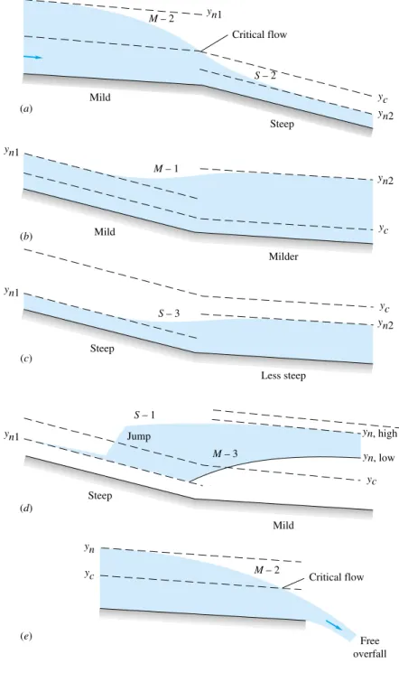
Since our initial depth y3 ft is smaller than yc, we know that the flow is supercritical. In practice, the channel slopes can vary enormously, S0S0(x), and the solution curves can intersect between two regimes. The only way this can happen physically is for the solution curve to smoothly pass through the critical depth, as shown.
The flow pattern accelerating from subcritical to supercritical resembles a converging-diverging nozzle in gas dynamics. For example, the upstream curve cannot be M-1, because breaks in slope would cause an S-1 curve, which would move away from uniformly steep flow. The depth will change smoothly along an S-3 curve to approach the new (higher) uniform flow.
Two cases are illustrated: (1) a jump to an S-1 curve to reach a high downstream normal depth and (2) a shift to an M-3 curve and then a jump to a lower downstream depth. This acts as a control section for the upstream flow, which then forms an M-2 curve and accelerates to critical flow near the weir. A weir, of which the common dam is an example, is a channel obstruction over which the flow must be diverted.
For simple geometries, the channel discharge Q correlates with gravity and with the blockage height H to which the upstream flow is backed up above the weir height (see Fig. 10.16). In both cases, the flow upstream is subcritical, accelerates to critical near the top of the weir, and overflows into a supercritical nap.
Composite-Flow Profiles
Flow Measurement and Control by Weirs
It is generally impossible to return smoothly from supercritical to subcritical flow without dissipation. The short-crested (or thin-plate) bulkhead must be vented to the atmosphere; i.e. it must escape from the weir crest. Crump” weir and various converging currents, are described in the text by Ackers et al.
It is possible to analyze weir flow by inviscid potential theory with an unknown (but solvable) free surface, as shown in Fig. However, here we simply use one-dimensional flow theory plus dimensional analysis to develop suitable weir flow rate correlations. It is assumed that the velocity head at any point 2 above the weir crest is equal to the total head upstream;.
If we accept for the moment, without proof, that the flow over the top draws down to hminH/3, the volume flow q Q/b over the top is approx.
Analysis of Sharp-Crested Weirs
Analysis of Broad-Crested Weirs
The main effect is due to the turbulent growth of the boundary layer displacements - thickness * at the crest compared to the upstream head H. If the nose is round, there is no significant effect of the weir height Y, at least when H/Y is 2.4. If a wide-crested dam has a sharp leading edge, so it is usually called a rectangular dam, the discharge may depend on the height of the Y dam.
For H/L 0.33 and H/Y 0.56, Cdin increases up to 10 percent due to each parameter, and the flow coefficient requires complex charts [19, ch. Estimate the discharge if the dam is (a) sharp-crested and (b) round-nosed with an unfinished cement wide crest 1.2 m long.
Other Thin-Plate Weir Designs
Backwater Curves
First determine the head H produced by the dam, using the theory of the full-width sharp-crested weir, Eq.
Summary
Problems
P10.6 Pebbles dropped successively at the same point into the stream of a 42 cm deep water channel create two circular waves, as in Figure P10.7 Pebbles dropped successively at the same point into the stream of a 65 cm deep water channel. , create two circular ones. P10.10 If surface tension is included in the probability analysis. a) Determine whether this term is affected by Reynolds number, Froude number or Weber number.
P10.25 The equilateral-triangle channel in Fig. P10.25 has constant slope S0 and constant Crew Factor n. Then, by analogy with Fig. Assumption of uniform flow and the rock-friction correlation of Eq. P10.33 Five of the sewer pipes of Prob. P10.35 In flood stage, a natural channel often consists of a deep main channel plus two flood plains, as in Fig.
P10.46 It is suggested that a channel that allows minimal erosion has a half-sine waveform, as in Figure P10.69. Given is the flow of a channel with a large width that closes off a lock, as in figure P10. 69 show that, for frictionless flow, the upstream velocity can be related to the water levels.
P10.93 Water in a horizontal channel accelerates uniformly over a bump and then undergoes a hydraulic jump, as in Fig. P10.86 A boris a hydraulic jump propagating upstream into a still or slower moving fluid, as in Fig. P10. 95 A 10 cm high bump in a wide horizontal water channel creates a hydraulic jump just upstream and the flow pattern in fig.
P10.114 Investigate the possibility of choking in the venturi of Fig. 10.49), neglects the effect of changes in width, db/dx, assuming them to be small. A bilge for water at 20 °C (cited in Ref. 19) shows a significant increase in the flow coefficient of V-notch weirs (Fig. P10.118) at low heads.
Word Problems
If the V-shaped weir has 30° and Y 50 cm, then, based on gradually varied theory, estimate the water depth 100 m upstream. If the weir does not drown, then, based on the gradually varied theory, estimate the flow rate at which the water depth will be 2 m 100 m upstream. Using progressively varied theory, estimate the distance from Lupstream at which the water depth will be 3 meters.
Suppose the river is a rectangular channel of weedy soil, 100 feet wide, with a flow rate of 800 ft3/s. FE10.1, if the water depth is 2 m and the uniform flow rate is 24 m3/s, what is the approximate value of Manning's roughness factor n.
Comprehensive Problems
Design Projects
The FE exam is fairly light on open-channel issues in the general (morning) session, but plays a major role in the specialized civil engineering (afternoon) exam.