Accordingly, Licensee agrees not to rely on the results of any use of Fluent, Inc.'s Products in determining the final design, composition, or structure of any Product.
USING THIS TUTORIAL GUIDE
- What’s in This Guide
- How to Use This Guide
- Font Conventions
- Using the Mouse
- Menus and Forms
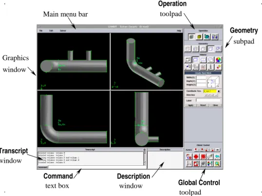
- Graphics Window
- GUI Components
- Graphics Window
- Main Menu Bar
- Operation Toolpad
- Form Field
- Global Control Toolpad
- Description Window
- Transcript Window and Command Text Box
The graphics window is the region of the GUI in which the model is displayed. The name of the command button that appears in the Description window of the GAMBIT GUI.
CREATING AND MESHING BASIC GEOMETRY
Problem Description
Strategy
Procedure Type
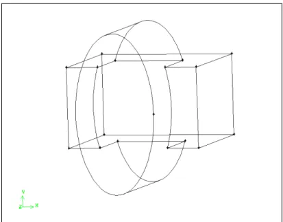
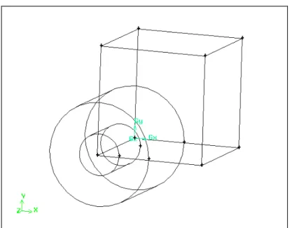
Create a Brick
Command button selection will be represented using this method for the remainder of this tutorial and in all subsequent tutorials. d) Left-click in the text input box to the right of Width in the Create Real Brick form and enter a value of 10 for Brick Width. e) Use the Tab key on your keyboard to move to the Depth text input box and enter 6 for the Brick Depth. A message appears in the Transcript window at the bottom left of the GAMBIT GUI to indicate that a volume has been created, named volume.1.
Create an Elliptical Cylinder 1. Create an elliptical cylinder
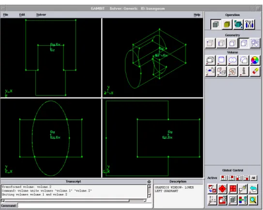
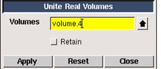
Unite the Two Volumes
You can rotate the screen (as shown in Figure 1-5) by holding down the left mouse button in the graphics window and moving the mouse to the left.
Manipulate the Display
Use the left mouse button to select the graphics window "sash anchor" - the small gray box in the center of the graphics window. Use the mouse to drag the frame anchor to the lower right corner of the graphics window.
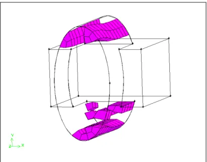
Mesh the Volume
Examine the Mesh
Each vertical bar on the histogram corresponds to a unique set of upper and lower quality boundaries. For a good mesh, the bars on the left side of the histogram are large and those on the right are small.
Save the Session and Exit GAMBIT
Summary
MODELING A MIXING ELBOW (2-D)
- Problem Description
- Strategy
- Procedure Start GAMBIT
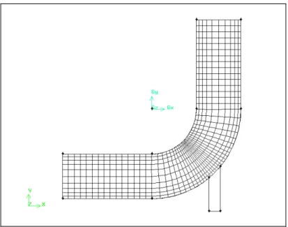
In this tutorial, you will build a 2D mesh using a "bottom-up" approach (as opposed to the "top-down" approach used in Tutorial 1). The mesh created in this tutorial is intended for use in FLUENT 4, so it must be a single-block structured mesh.
Select a Solver
Create the Initial Vertices
This creates a background grid with four cells in the x direction and enters the x coordinates into the XY_plane X Values list. You can zoom out the view by holding down the right mouse button while moving the cursor vertically up in the graphics window.
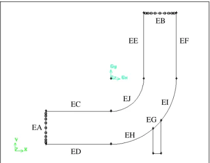
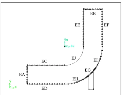
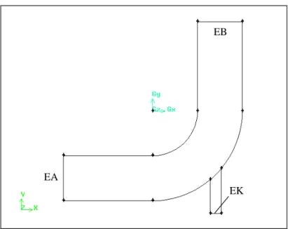
Create Arcs for the Bend of the Mixing Elbow
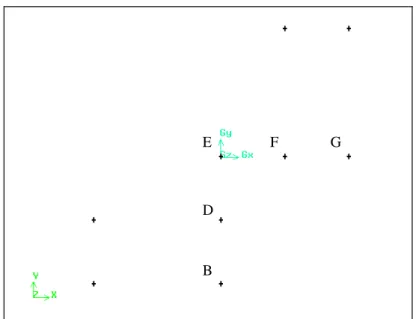
Alternatively, you can continue to hold down the Shift key and click the right mouse button in the graphics window to accept the vertex selection and move the focus to the endpoint list box. The center of the arc is the vertex in the center of the graphics window (vertex E in Figure 2-5).
Create Straight Edges
Create the Small Pipe for the Mixing Elbow
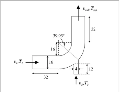
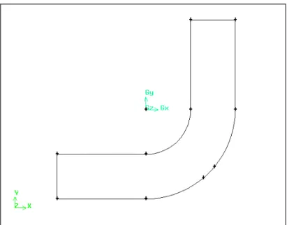
This is the angle between the horizontal direction and the position of the right side of the opening of the small tube on the bend of the mixing elbow, as shown in Figure 2-1. The arch is divided into two parts, and another vertex is created on the bend of the mixing elbow, as shown in Figure 2-9.

Create Faces From Edges
Note that the edges must form a continuous loop, but they can be selected in any order. An alternative method to select multiple edges is to Shift-Left-drag a box around the edges.
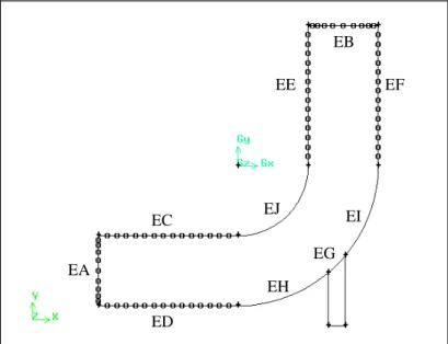
Specify the Node Distribution
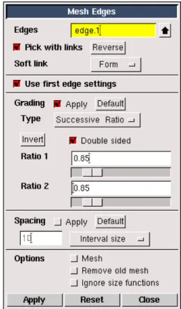
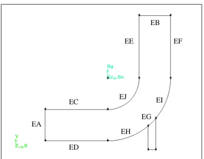
GAMBIT will create 10 intervals on the edge. . g) Click the Apply button at the bottom of the form. Set the graduation for the inner bend of the mixing elbow. a) Select the edge labeled EJ in Figure 2-18. b) Make sure Apply is selected to the right of Gradation in the Mesh Edges form and enter a value of 0.85 for the ratio.
Create Structured Meshes on Faces
Note that GAMBIT calculates the number of nodes on the inside bend of the blending elbow and displays these nodes before creating the mesh on the face. This is an example of "enforced mapping" where GAMBIT automatically changes the face vertex type on the face to satisfy the selected meshing scheme.
Set Boundary Types
Move-left-click the main inflow for the mixing elbow in the graphics window (labeled EA in Figure 2-22) and click Apply to accept the selection. To display the boundary types in the graphics window, select the Show Labels options on the Specify Boundary Types form.).
Export the Mesh and Save the Session
Summary
Since the mesh is to be used in FLUENT 4, it was generated in a single block, structured manner. Compared to Tutorial 1, which left out some details, all the steps required to create a mesh ready to read into the solver were covered, including how to set boundary types, choose a specific fluid solver, and finally output the mesh file .
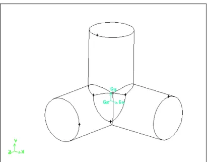
MODELING A THREE-PIPE INTERSECTION (3-D)
- Problem Description
- Strategy
- Procedure Start GAMBIT
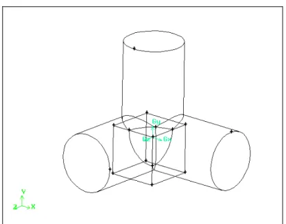
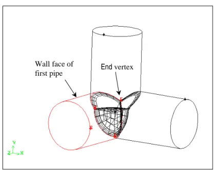
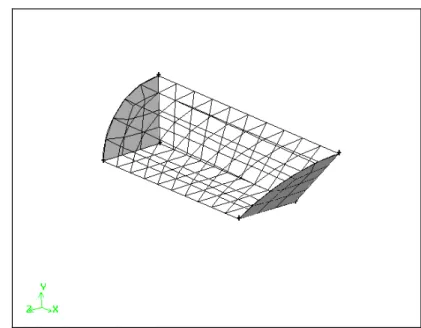
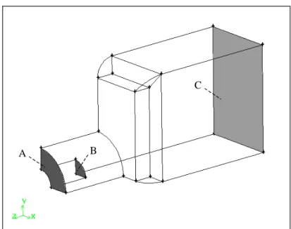
The geometry can be represented as three intersecting cylinders and a spherical octant at the intersection corner. The first decommissioning involves the use of bricks to split off part of the three-way intersection.
Create the Geometry
Using the same Height and Radius 1 as above, select Positive Y from the list to the right of Axis Location. Click the FIT TO WINDOW command button at the top left of the Global Control toolpad to view all three cylinders.
Decompose the Geometry
GAMBIT will divide the volume with the three pipes using the brick, leaving two volumes: the three pipes (volume.1) and the octant of the sphere (volume.3). Select the Off radio button to the right of Visible near the bottom of the form and click Apply.
Journal Files
A black box in the LINE EXECUTION COLUMN of the Edit/Run Journal form indicates that the line is selected. Each line of the log was displayed in the Transcript window as it was executed.
Turn Off Automatic Smoothing of the Mesh
GAMBIT displays variables for which default values have been set in a list in the Edit Default Values form. AUTO_SMOOTH will be displayed in the text input box at the bottom of the list, and its default value will be displayed in the value text input box.
Apply Boundary Layers at Walls
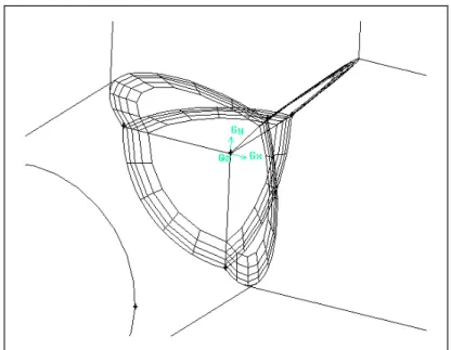
The boundary layer will appear on the edge. . g) Check that the arrow indicating the direction of the boundary layer points towards the origin (Gx, Gy, Gz). Repeat the above steps to create the same boundary layer on the three curved edges where the three pipes intersect, as shown in Figure 3-12.
Mesh the Sphere Octant Volume
Mesh the Pipe Volumes
Mesh the second pipe by using the Submap scheme on the wall face of the pipe and by using the Cooper interference scheme to mesh the volume. Select the wall face of the second pipe (shown in Figure 3-16) in the graphics window.
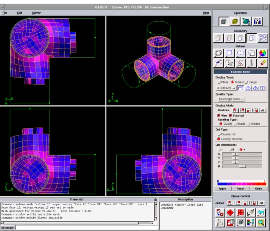
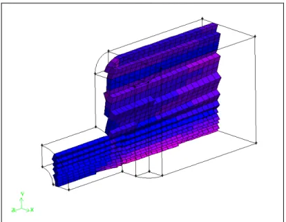
Examine the Quality of the Mesh
The “+” option means that only elements on the positive side of the cut are displayed. This divides the graphics window into four quadrants and displays a different view of the spherical mesh section in each quadrant.
Set Boundary Types
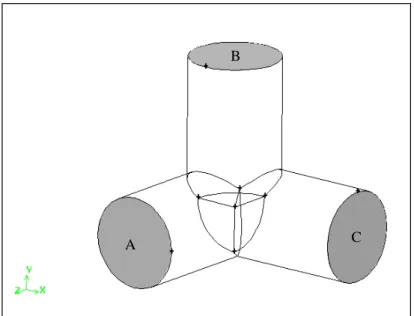
Make sure that ELEMENT_SIDE is still selected in the Type option menu and Shift-left-click the end of one of the other pipes in the graphics window (the face labeled B in Figure 3-21). Check that ELEMENT_SIDE is still selected in the Type option menu and select all the wall faces (the outer walls of the three pipes and the outside of the sphere octant) in the graphics window.
Export the Mesh and Save the Session
Summary
Before creating the mesh, you decomposed the three-tube geometry into four volumes: the three individual tubes and the wedge-shaped corner of the junction (the sphere "octant").
MODELING A COMBUSTION CHAMBER (3-D)
- Problem Description
- Strategy
- Procedure Start GAMBIT
Similarly, you will blend the annular face of the primary inlet with a fine card mesh. Finally, use the automatic Cooper tool to blend the remaining faces and volume.
Set the Default Interval Size for Meshing
SIZE will appear in the space at the end of the list and its default value will appear in the Value text input box.
Create Two Cylinders
Subtract the Small Cylinder From the Large Cylinder 1. Create one volume from the two cylinders by subtracting one cylinder from the other
Alternatively, you can continue to hold down the Shift key and click the right mouse button in the graphics window to accept the selection of the large cylinder and move the focus to the Subtract Volumes list box. Selecting the cylinders in this order ensures that the small cylinder is subtracted from the large cylinder and not the other way around.
Shade and Rotate the Display
Remove Three Quarters of the Cylindrical Volume
The order in which the two volumes are selected is not important for the outcome of the operation, but does affect the numbering of subsequent geometric entities. The cylindrical volume will be cut off so that only the part inside the brick remains, as shown in Figure 4-9.
Create the Chamber of the Burner
The order in which you select the two volumes is not important when merging them.
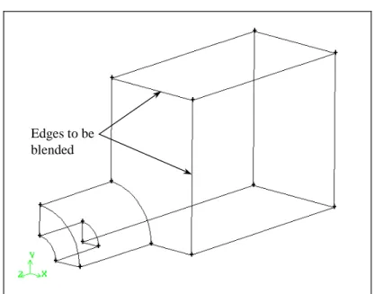
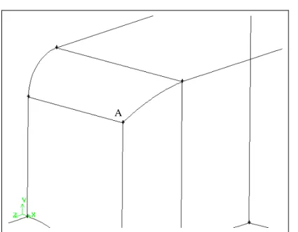
Blend the Edges of the Chamber
Select Constant radius around (the default) under Options in the Edge blend type form. iii. Click Apply in the Edge Blend Type form and close the form. b) Hold down Shift and left-click the volume in the graphical window.
Decompose the Geometry
Swipe the same face in a different direction. a) Select the face labeled H in Figure 4-19. b) Left-click in the list box to the right of Edge to make the Edge list box active. Volume list box located above the Divide By section to .. k) Select the second volume created using the swipe face method. l) Click Apply.
Generate an Unstructured Hexahedral Mesh In the meshing section of this tutorial you will use
You can also click Reset in the Mesh Volumes form to deselect all faces and then select the correct faces. You can see a shaded view of the mesh using the RENDER MODEL command button in the Global Control toolbar.
Examine the Quality of the Mesh
When you select the Display Type:Range option on the Examine Mesh form, GAMBIT displays the Show worst element option immediately below the statistics displayed below the histogram. If you select the Show worst item option, GAMBIT will only display the "worst" item as determined by the current quality metric of the quality type.
Set Boundary Types
Verify that VELOCITY_INLET is still selected in the Type setting menu, select the face marked B in Figure 4-35, and click Apply. Make sure SYMMETRY is still selected in the Type menu and select the two faces at the bottom of the geometry (the faces marked F and G in Figure 4-36).
Export the Mesh and Save the Session
Summary
In this tutorial, you created the geometry and hexahedral mesh for a 3-D combustion chamber using a top-down construction approach. Next, the geometry was decomposed into smaller volumes for which the Cooper brass scheme could be used.
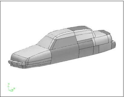
SEDAN GEOMETRY—VIRTUAL CLEANUP
- Problem Description
- Strategy
- Procedure 1. Copy the file
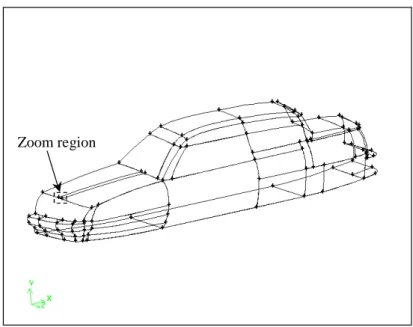
You will create a grid on the outside of the body; so you will create a brick around the limo to represent the flow domain. Since the imported geometry only consists of the car body, you need to create an appropriate domain around the car to perform the CFD analysis (this is loosely equivalent to placing the car in a wind tunnel).
Import the IGES File As-Is File → Import → IGES …
Click the SPECIFY COLOR MODE command button on the Global Control toolbar to change the graphics display to connectivity-based coloring. Ctrl-drag the mouse in the graphics window to create the zoom area box shown in Figure 5-2 above (on the front of the sedan hood).