저작자표시-비영리-변경금지 2.0 대한민국 이용자는 아래의 조건을 따르는 경우에 한하여 자유롭게
l 이 저작물을 복제, 배포, 전송, 전시, 공연 및 방송할 수 있습니다. 다음과 같은 조건을 따라야 합니다:
l 귀하는, 이 저작물의 재이용이나 배포의 경우, 이 저작물에 적용된 이용허락조건 을 명확하게 나타내어야 합니다.
l 저작권자로부터 별도의 허가를 받으면 이러한 조건들은 적용되지 않습니다.
저작권법에 따른 이용자의 권리는 위의 내용에 의하여 영향을 받지 않습니다. 이것은 이용허락규약(Legal Code)을 이해하기 쉽게 요약한 것입니다.
Disclaimer
저작자표시. 귀하는 원저작자를 표시하여야 합니다.
비영리. 귀하는 이 저작물을 영리 목적으로 이용할 수 없습니다.
변경금지. 귀하는 이 저작물을 개작, 변형 또는 가공할 수 없습니다.
공학박사 학위논문
Electrohydrodynamic Jet-Printed Transistors and Applications with Single-Walled Carbon Nanotubes
정전기수력학 인쇄를 활용한
단일벽 탄소나노튜브 기반 트랜지스터 및 응용
2020 년 8 월
서울대학교 대학원 전기컴퓨터공학부
성 낙 현
Electrohydrodynamic Jet-Printed Transistors and Applications with
Single-Walled Carbon Nanotubes
정전기수력학 인쇄를 활용한
단일벽 탄소나노튜브 기반 트랜지스터 및 응용 지도 교수 홍 용 택
이 논문을 공학박사 학위논문으로 제출함 2020 년 6 월
서울대학교 대학원 전기컴퓨터공학부
성 낙 현
성낙현의 공학박사 학위논문을 인준함 2020 년 7 월
위 원 장 : 정 윤 찬 (인)
부위원장 : 홍 용 택 (인)
위 원 : 이 수 연 (인)
위 원 : 박 진 성 (인)
위 원 : Steve Park (인)
i
Abstract
Electrohydrodynamic Jet-Printed Transistors and Applications with
Single-Walled Carbon Nanotubes
NARKHYEON SEONG DEPARTMENT OF ELECTRICAL ENGINEERING
AND COMPUTER SCIENCE COLLEGE OF ENGINERRING SEOUL NATIONAL UNIVERSITY
As the demand and research for electronic devices on flexible and stretchable substrates gradually continues comparable to the conventional rigid silicon-based electronic devices, interest in new semiconducting materials capable of low-temperature processes and large-area processes is increasing. Single-walled carbon nanotube (SWCNT) is one of the representative materials satisfying the new interests thanks to its excellent electrical and mechanical properties.
SWCNT can be advantageous for non-vacuum, low-temperature, and large-area processes in response to various solution processes such as dipping, inkjet printing, and gravure printing. For high-
ii
performance devices with low power consumption based on next- generation electronics, the demand for ultra-fine patterning technology based on the solution process is also increasing.
In this thesis, SWCNT-based all electrohydrodynamic-jet (E-jet) printing system was established, a SWCNT-based thin-film transistor (SWCNT-TFT) with a channel length of 5 microns was implemented through the system. In addition, by developing and grafting technology to control the threshold voltage of SWCNT- TFTs based on the solution process, we have demonstrated highly integrated and high-resolution SWCNT-based applications including logic gate, pixel circuits for image detector and display. In addition to the micrometer scale fine pattern technology by the E-jet printing system, a new solution process-based vertical stacking technology is also introduced to further improve the transistor density, enabling high-resolution, highly integrated electronic applications in a continuous environment without any vacuum or high temperature process. The technology introduced in this thesis for high performance, high resolution, and high integration of SWCNT-based devices makes it possible to fabricate a 250 pixel per inch active matrix backplane utilizing only the solution process.
Keyword: single-walled carbon nanotube (SWCNT), thin-film transistor (TFT), electrohydrodynamic jet printing, active pixel
Student Number: 2012-20790
iii
Contents
Abstract i
Contents iii
List of Tables ix
List of Figures xi
1 Introduction 1
1.1 Single-Walled Carbon Nanotubes ... 1
1.2 Band structure of SWCNTs ... 8
1.2.1 Energy bandgap of SWCNTs ... 8
1.2.2 Density of states for SWCNTs ... 11
1.2.3 Detection for classifying species of SWCNTs . 13 1.3 Sorting out semiconducting SWCNTs ... 16
1.3.1 Pre-deposition of the nanotubes and sorting later ... 16
1.3.2 First sorting out SWCNTs and deposition later ... 18
1.4 Operation of SWCNT-TFTs ... 21
1.4.1 SWCNT-TFTs as Schottky-barrier FETs ... 22
1.4.2 Random network of SWCNTs ... 26
iv
1.5 Reported SWCNT-TFTs and applications ... 28
1.6 Technical points for microelectronics based on SWCNT-TFTs ... 32
1.7 Organization ... 34
2 Tunable threshold voltage in single-walled carbon nanotube thin-film transistors 35
2.1 Introduction ... 352.2 Experimental details ... 37
2.2.1 Fabrication process for solution-processed SWCNT-TFTs ... 37
2.2.2 Post-treatments for tunable threshold voltage in solution-processed SWCNT-TFTs and measurement of their electrical properties ... 38
2.3 Results and discussion ... 39
2.3.1 Post-chemical encapsulation for tunable threshold voltage ... 39
2.3.2 Contact resistance analysis by the Y-function method in SWCNT-TFTs employing chemical encapsulation ... 41
2.3.3 Shift of energy band in SWCNT-TFTs ... 42
2.3.4 Cycling tests for post-treatments ... 45
2.3.5 SWCNTs-based p-type only inverter ... 46
2.4 Conclusion ... 49
v
3 All electrohydrodynamic-jet printing system for
single-walled carbon nanotube thin-film transistors 50
3.1 Introduction ... 50
3.2 Experimental details ... 55
3.2.1 Ink manufacturing for E-jet printed metal, dielectric, and active layers ... 55
3.2.2 Optimized E-jet printing conditions and fabrication process for all E-jet printed SWCNT-TFTs ... 57
3.3 Results and discussion ... 60
3.3.1 Constituting of all E-jet printing system ... 60
3.3.2 Optimized E-jet printed metal electrode ... 63
3.3.3 Optimized E-jet printed polymer dielectric ... 67
3.3.4 E-jet printing of S/D electrodes with short channel length ... 74
3.3.5 Formation of SWCNT networks in E-jet printing system ... 76
3.3.6 Overall process for all E-jet printing and electrical characteristics of all E-jet printed SWCNT-TFTs ... 78
3.4 Conclusion ... 83
vi
4 All electrohydrodynamic-jet printing system based circuit design for high-resolution and
highly integrated applications 85
4.1 Introduction ... 85 4.2 Experimental details ... 89
4.2.1 In-situ fabrication of via-hole and diode- connected SWCNTs-TFTs in all E-jet
printing system ... 89 4.2.2 Fabrication process of all E-jet printed
inverter with vertically stacked
SWCNT-TFTs ... 90 4.2.3 Fabrication process of all E-jet printed active
pixel sensor for image sensor with vertical
stacking structure ... 92 4.2.4 Fabrication process of all E-jet printed pixel
circuit for active matrix polymer light-emitting diode with vertical stacking structure ... 95 4.3 Results and discussion ... 98
4.3.1 In-situ via-hole formation technology based on all E-jet printing system ... 98 4.3.2 Additional E-jet printing of PVP layer on the
SWCNT-TFTs ... 99 4.3.3 Electrical characteristics for all E-jet printed
diode-connected SWCNT-TFTs ... 101 4.3.4 Electrical characteristics for all E-jet printed
vii
inverter with vertically stacked
SWCNT-TFTs ... 103 4.3.5 Structure design for active pixel sensor
based on vertically stacked E-jet printed
SWCNT-TFTs ... 107 4.3.6 All E-jet printed pixel circuit for active matrix
polymer light-emitting diode with vertical
stacking structure ... 110 4.4 Conclusion ... 118
5 Conclusion 119
viii
Appendix 121
A.1 Post-treatment with DI-water on SWCNT-TFT ... 121 A.2 Variation of characteristics of SWCNT-TFTs by
post-treatment time with NH4OH ... 123 A.3 Surface energy variation by a ratio between
cross-liking agent and PVP ... 124 A.4 Analysis for surface roughness parameters ... 125 A.5 Electrical characteristics of E-jet printed
SWCNT-TFTs according to channel structure ... 128
Bibliography 130
Abstract in Korean 149
ix
List of Tables
2.1 Electrical parameters of the solution-processed SWCNT-TFTs with and without post-treatments by NH4OH and HNO3 ... 40 3.1 Comparison between solution printing technologies 52 3.2 Optimized jetting conditions for the E-jet printed
inks ... 58 3.3 Optimized parameters for fabrication of E-jet printed
silver electrode ... 67 3.4 The boiling point, vapor pressure, and surface tension
for ethanol and PGMEA ... 70 3.5 Roughness parameters for E-jet printed PVP films 72 3.6 Optimized parameters for fabrication of E-jet printed
PVP ... 74 3.7 Comparison of electrical parameters for the pristine and
NH4OH-treated all E-jet printed SWCNT-TFTs .... 82 4.1 Electrical properties of TFTs in the pixel sample
corresponding to Figure 4.17 ... 114 A.1 Electrical characteristics for SWCNT-TFT samples
corresponding to Figure A.1 ... 122 A.2 Electrical characteristics for SWCNT-TFT samples
corresponding to Figure A.2 ... 124 A.3 Surface energy analysis of PVP:CLA films with
x
Owens-Wendt model ... 125 A.4 Electrical properties for E-jet printed SWCNT-TFTs
with the rectangular S/D and the Corbino type S/D electrodes ... 129
xi
List of Figures
1.1 Applications in various fields with SWCNTs ... 2 1.2 (a) Epoxy nanocomposite fabrication process with
enhanced tensile properties through CNT addition and (b) its stress–strain curve. (c) Pressure sensor utilizing mechanical and electrical properties of CNTs ... 3 1.3 (a) DNA detecting device based on SWCNT (b)
Chemical Reaction Mechanism between hydrogen sulfide (H2S) and CNT ... 4 1.4 (a) photoresponsivity of SWCNT. It shows weak
reactivity in some infra-red regions (630 nm & 980 nm) (b) CNT-based transparent conductive film ... 5 1.5 A diagram comparing the mobility and on/off current
ratio of Silicon, organic, oxide, and SWCNT ... 7 1.6 (a) The unrolled two-dimensional graphene sheet
lattice of a (5,2) tube. Carbon atoms in the shaded region are rolled in the direction of the chiral vector, forming the nanotube structure in (b) ... 9 1.7 Density of states for (a) metallic and (b) semi-
conducting SWCNTs ... 12 1.8 Kataura plot showing the relationship between the
diameter and energy bandgaps of SWCNTs ... 13
xii
1.9 (a) resonance Raman spectroscopy to detect the energy difference of a photon between before and after incident. (b) SWCNT resonating in the radial direction of the nanotube. (radial breathing mode; RBM) (c) The relationship between the Raman shift in RBM of SWCNTs and the diameter and energy bandgaps of nanotubes. (d) The peaks of the Raman shift can be detected in the SWCNT film deposited through resonance Raman spectroscopy measurement ... 14 1.10 Acquisition process and result image of aligned
semiconducting SWCNT array using thermo-capillary flow method ... 18 1.11 (a) Separation of SWCNTs by density gradient
ultracentrifugation method. Layers are divided according to the diameter of nanotubes. (b) Separation of SWCNTs through Polymer assisted sorting method ... 20 1.12 (a) A Schottky-barrier field-effect transistor with
bottom gate-top contact structure including a channel composed of semiconducting SWCNT and (b) its energy band diagram in the channel. (c) Energy band diagram and (d) transfer characteristics of SWCNT- based transistors with ambipolar characteristics ... 23 1.13 (a) Energy band diagram of SWCNT-based FET with
a local polarization layer formed on the interface of the contact. (b) A gate bias suppresses of the barrier
xiii
... 24 1.14 (a) Oxygen, water molecules and chemical functional
groups around the nanotubes and interface. (b) Passivation layer surrounding SWCNTs in the channel ... 25 1.15 (a) SEM image of SWCNT network according to the
process method. (b) Junctions between CNTs inside the channel highlighted in red. (c) Correlation between the number of junctions and mobility ... 27 1.16 Mobility and on/off current ratio of the SWCNT-TFTs
according to SWCNT formation method ... 28 1.17 (a) Fully printed logic gates on polyimide with SWCNTs.
(b) SWCNT-TFTs that operate on physical deformation of the substrate ... 29 1.18 (a) CMOS-type SWCNT-TFTs, and (b) CMOS NOR
gate. (c) Transfer characteristics for p- and n- type SWCNT-TFTs. (d) Microprocessor made of over 14,000 SWCNT-based transistors on silicon wafers ... 31 2.1 (a) The schematic cross-section of a solution-
processed SWCNT-TFT and (b) an optical image of a SWCNT-TFT with thermally evaporated gold as S/D electrodes ... 38 2.2 (a) and (b) Transfer curves and calculated Y-function
of NH4OH- and HNO3- treated samples, respectively.
(c) and (d) Distribution charts of the low field mobility
xiv
and VT for each group ... 40 2.3 (a) Contact resistance of SWCNT-TFTs before and
after the post-treatments. (b) Variation in contact resistance for treated SWCNT-TFTs with respect to that of pristine one (𝑅𝐶0) ... 44 2.4 Schematic energy band diagrams for the samples after
post-treatments (black dot-line means the energy level of the pristine SWCNT) ... 44 2.5 (a) Transfer characteristics of sequentially treated
SWCNT-TFTs with HNO3 and NH4OH. (b) The low field mobility, VT, and contact resistance of SWCNT- TFTs for each sequence ... 46 2.6 (a) SWCNT-TFTs based p-type only inverter circuit.
(b) Transfer characteristics of SWCNT-TFTs with and without VT tuning technology. (c) and (d) Voltage transfer characteristics of SWCNT-TFT based inverters with and without VT tuning technology ... 48 3.1 (a) Taylor cone formation and ejection of an ink due to
electric field between the nozzle with 2 micrometer hole and the substrate (b) 3D structure electrode pattern via E-jet printing ... 54 3.2 (a) Schematic diagram of E-jet printing system. (b)
Printing chamber in E-jet printing equipment. (c) High voltage unit and nozzle camera of E-jet printer ... 61 3.3 Diagram for technical points in constituting of all E-jet
printing system ... 62
xv
3.4 (a) and (b) Optical image of printed metal line without and with optimization of waveform. (c) and (d) Images obtained by FE-SEM for 2 stacked and 3 stacked printed line with nanoparticle-type Ag ink, respectively. ... 64 3.5 (a) and (b) Optical and FE-SEM images for E-jet
printed Ag line. (c) Current-voltage graph of E-jet printed Ag line according to the number of printing stacks. (d) Line profile obtained by AFM of Ag line stacked 4 times. The top right inset is the image of the printed line obtained by AFM ... 66 3.6 Improved wetting properties of the E-jet printed PVP
layer by increasing a ratio of cross-liking agent ... 68 3.7 (a) and (b) Line profile of E-jet printed PVP films with
the single solvent and the mixed solvent based-PVP ink, respectively. The subsequent silver line shows an unstable connection at the edge of the PVP film in (a) ... 70 3.8 (a) Thickness, (b) RMS, (c) skewness, and (d)
kurtosis of E-jet printed PVP films according to line pitch and printing speed ... 71 3.9 (a) Optical image of a PVP thin film printed once with
optimized process parameters. (b) Line profile of the PVP thin films printed once (black line) or twice (red line) ... 73 3.10 (a) Leakage current vs applied field and (b) areal
xvi
capacitance vs frequency for E-jet printed PVP stacked twice. The inset in (a) is the optical image of PVP printed twice ... 73 3.11 Optical image of S/D electrodes before and after HMDS
treatment on the surface of E-jet printed PVP layer ... 75 3.12 SEM image showing the difference in density of
adsorbed SWCNTs in the channel region in red square border when the substrate was immersed in the PLL and the PLL was directly printed ... 78 3.13 Overall fabrication process for all E-jet printed
SWCNT-TFTs ... 78 3.14 (a) Optical image, (b) transfer characteristics, and (c)
output characteristics for all E-jet printed SWCNT- TFT ... 80 3.15 (a) Transfer characteristics and (b) output
characteristics for NH4OH-treated all E-jet printed SWCNT-TFTs ... 82 4.1 Vertical structure for (a) Inkjet-printed inverter with
organic semiconducting materials and (b) capacitive fingerprint sensor with oxide semiconductor ... 86 4.2 (a) Circuit configuration and (b) schematic diagram of
the vertically stacked p-type only inverter based on all E-jet printed SWCNT-TFTs ... 91 4.3 The overall fabrication steps for all E-jet printed
SWCNT-based inverter with vertically stacked
xvii
structure ... 92 4.4 (a) Circuit and (b) schematic diagram of the vertically
stacked APS based on all E-jet printed SWCNT-TFTs ... 94 4.5 The overall fabrication steps for all E-jet printed
SWCNT-based APS with vertically stacked structure ... 94 4.6 (a) Circuit and (b) schematic diagram of the vertically
stacked pixel circuit for active matrix PLED based on all E-jet printed SWCNT-TFTs ... 96 4.7 The overall fabrication steps of all E-jet printed
SWCNT-based pixel circuit for active matrix PLED with vertically stacked structure ... 97 4.8 (a) and (b) Optical images for the E-jet printed PVP
films containing the via-hole and (c) metal-insulator- metal structure with in-situ printed via-hole. (d) Line profile of the via-hole with the diameter of 10 ㎛. I-V characteristics for the interconnect are shown in the inset of (d) ... 99 4.9 Change in the transfer characteristics by printing the
upper PVP film on (a) pristine SWCNT-TFT and (b) NH4OH-treated SWCNT-TFT. (c) Comparison of the transfer characteristics of PVP-passivated SWCNT- TFTs with or without NH4OH treatment
... 101 4.10 Schematic diagram and optical image of all E-jet
xviii
printed diode-connected SWCNT-TFT ... 102 4.11 Transfer characteristics of (a) the conventional TFT
without via-hole and (b) the diode-connect TFT through the via-hole located at the center of the PVP gate insulating layer. The black line is the data of the sample where the SWCNT is exposed to the air as it is, and the red line is the data of the sample with the additional PVP layer printed on the SWCNT ... 102 4.12 (a) Optical image of all E-jet printed p-type only
inverter based on vertically stacked SWCNT-TFTs. (b) and (c) Transfer characteristics for driving TFTs and load TFTs in the fabricated inverter, respectively
... 105 4.13 Voltage transfer characteristics and voltage gain for all
E-jet printed SWCNT-based inverter ... 106 4.14 (a) and (b) Optical image and schematic diagram for all
E-jet printed diode-connected SWCNT-TFT. (c) Change in reverse bias current according to IR exposure ... 108 4.15 (a) Schematic diagram and optical image of all E-jet
printed APS with vertically stacked structure. (b) Proposed APS array structure based on E-jet printing system ... 110 4.16 (a) Circuit configuration of pixel circuits for active
matrix PLED. (b) Optical image of vertically stacked E-jet printed pixel circuits excluding the cathode
xix
electrode. (c) and (d) Transfer characteristics for switching and driving transistors in the pixel circuits, respectively ... 112 4.17 Transfer characteristics corresponding to the best
sample among the pixel circuits ... 114 4.18 Improved wetting properties of ZnO layer on the bottom
backplane structure by PLL-based surface treatment ... 115 4.19 Operation of pixel circuit for active matrix PLED.
Driving current according to data signal when switching TFT is always (a) off or (b) on. Driving current according to the state of the switching TFT in a fixed data signal ((c) black or (d) light) state ... 116 A.1 Effects of post-treatment with DI-water on SWCNT-
TFTs. (a) Pristine samples. Immersed into DI-water for (b) 5 minutes and (c) 15 minutes ... 122 A.2 Changes in transfer characteristics of SWCNT-TFTs
with NH4OH post-treatment time. (a) Pristine samples.
NH4OH treatment for (b) 5 minutes and (c) 15 minutes ... 123 A.3 (a) Distribution of roughness according to the sign of
skewness. (b) Distribution of roughness according to the value of Kurtosis ... 126 A.4 (a) Optical images and (b) line profiles of E-jet printed
PVP surfaces according to printing speed and line pitch ... 127
xx
A.5 (a) Optical image, (b) transfer characteristics and (c) output characteristics of E-jet printed SWCNT-TFTs with rectangular type S/D ... 128 A.6 (a) Optical image, (b) transfer characteristics and (c)
output characteristics of E-jet printed SWCNT-TFTs with Corbino type S/D ... 129
1
Chapter 1 Introduction
1.1 Single-Walled Carbon Nanotubes
Semiconducting single-walled carbon nanotubes (SWCNTs) made of a single layer of the carbon nanotube have attracted a great deal of attention as semiconducting materials of future nanoelectronics devices thanks to their unique mechanical, chemical, optical, and electrical characteristics. Figure 1.1 introduces the key features of SWCNTs used in various fields. Carbon nanotubes have a unique structure in which carbon atoms are combined into a one- dimensional cylindrical shape. Unlike graphene with two-dimensional form or fullerene with three-dimensional form of carbon, the carbon nanotube is rolled in a specific direction, called a chiral vector, and the diameter of the cylinder and the arrangement of the carbon atoms change depending on the length and direction of the vector. Especially, it is important to determine whether SWCNT has metallic or semiconducting properties according to the chiral vector. More details are described in Section 1.2.
2
Figure 1.1 Applications in various fields with SWCNTs. (a) Nanocomposite with enhanced mechanical properties by mixing SWCNTs [1]. (b) SWCNT-based chemical sensor that detects changes in electrical properties in response to external chemicals [2].
(c) SWCNT-based transparent electrode film [3]. (d) Integrated circuits using SWCNT-based transistors [4].
Mechanical features SWCNTs have outstanding tensile strength because of their tight nanostructure and binding force among carbon atoms composed of only sp2 bonds. Young's modulus of SWCNT is a very high value above 100 GPa, indicating that SWCNT is one of the strongest materials in terms of tensile strength in the
(a) (b)
(d) (c)
3
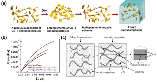
axial direction [5]. On the other hand, SWCNT is relatively of elasticity in the radial direction of the nanotubes. Using these unique mechanical properties, many studies have been reported to increase elasticity or strength in combination with epoxy polymers or other nanomaterials as shown in Figure 1.2 (a) and (b) [6]. Applications such as flexible pressure sensors that combine the unique mechanical properties of CNT with the electrical properties of SWCNT to be described later are also reported, as shown in Figure1.2 (c) [7].
Figure 1.2 (a) Epoxy nanocomposite fabrication process with enhanced tensile properties through CNT addition and (b) its stress–
strain curve [6]. (c) Pressure sensor utilizing mechanical and electrical properties of CNTs [7].
Chemical sensing properties SWCNT changes the electrical characteristics depending on the type of attachment of various chemicals on the surface of the nanotubes. In this regard, research
(a)
(b) (c)
4
on chemical modification of nanotubes has also been conducted [8].
For example, research into CNT grafting in various chemical sensing devices has been actively studied, including bio-chemicals such as glucose [9], DNA [10] and environmental chemicals including humidity [11], hydrogen sulfide [12], carbon monoxide [13], and acidity [14] (see Figure 1.3). Thanks to the sensitive nature of SWCNT's conductance which changes even at very low concentrations of tens of ppm, it can be used in next-generation wearable skin-attached glucose detection sensors and human body mimicking chemical sensor.
Figure 1.3 (a) DNA detecting device based on SWCNT [10]. (b) Chemical Reaction Mechanism between hydrogen sulfide (H2S) and CNT [12].
Analytes binding to DNA
Single stranded DNA
Carbon Nanotube
Gold Contact
(b) (a)
5
Optical properties In terms of optical characteristics, SWCNT has a unique optical feature that is suitable for transparent electronic devices. In visible light areas at 400 to 700 nm wavelengths, the light absorption rate of the SWCNT is very low, and the photoresponse is slightly shown in some infrared (IR) regions as shown in Figure 1.4 (a) [15]. Using these characteristics, some studies and applications have been conducted and reported about IR sensors based on SWCNT [15], [104], [105]. Also, the diameter of nanotubes is very thin with several nanometers, and the thickness of the film is also stacked on a nanometer scale, resulting in a transmittance of more than 80 percent in the general visible light area (see Figure 1.4 (b)) [16]. Therefore, studies on transparent electrodes using metallic SWCNTs or transparent transistors using semiconducting SWCNTs having little reactivity to light have been reported [17].
Figure 1.4 (a) photoresponsivity of SWCNT. It shows weak reactivity in some infra-red regions (630 nm & 980 nm) [15]. (b) CNT-based transparent conductive film [16].
(a) (b)
6
Electrical features Above all, a single SWCNT exhibits excellent electrical properties such that the theoretical carrier mobility can reach about 100,000 cm2/V⋅s [18]. Generally, solution-process based SWCNT consists of a random network structure that is woven into several strands rather than a single nanotube. In this case, the mobility is reduced to 1 to 100 cm2/V⋅s because the contact resistance at the junctions between the nanotubes works greatly [4]. Nevertheless, with comparing mobility in various semiconductor materials shown in Figure 1.5, this mobility is comparable to that of oxide materials such as indium-gallium-zinc oxide, which exhibit higher electrical characteristics than conventional amorphous silicon or organic semiconductor materials.
Moreover, recently reported SWCNT-based transistors show high on-off current ratio of over 100,000 as well as high mobility [19].
Thus, solution processed SWCNT has the advantage of being able to take both high electrical performance and process benefits because it is easily deposited in the solution process at room temperature.
7
Figure 1.5 A diagram comparing the mobility and on/off current ratio of Silicon, organic, oxide, and SWCNT [4].
Consequently, SWCNT has attractive features as a next- generation flexible electronic material in mechanical, chemical, optical, and electrical properties. There are some issues to be explained later, but thanks to its excellent electrical properties and easy processability at room temperature, SWCNT has been noted as much as polymer-based organic semiconducting materials or oxide semiconducting materials that have been widely used as materials for next-generation flexible transistors. This dissertation covers the entire production of high-resolution and highly integrated solution- processed SWCNT-based circuits including logic circuit and active pixel circuit incorporating electrohydrodynamic jet-printing (E-jet
8
printing), one of the printing technologies capable of ultrafine patterns, from the manufacture and analysis of solution processed SWCNT thin film transistors (SWCNT-TFTs). The technologies necessary for the fabrication of SWCNT-TFT based on the low- temperature solution process are covered in Chapter 2 and SWCNT- TFT incorporating E-jet printing and the technologies for high- intensity circuits are described in Chapters 3 and Chapter 4.
Specifically, to find out the issues arising from the solution process- based SWCNT-TFT, it is necessary to understand the specific electrical properties of SWCNT, and the contents are described in the next sections.
1.2 Band structure of SWCNTs
1.2.1 Energy bandgap of SWCNTs
As mentioned above, carbon nanotube is a form in which a sheet of graphene is rolled in the direction of a specific vector called a chiral vector, as shown in Figure 1.6. A so-called (𝑛, 𝑚) carbon nanotube has the below chiral vector 𝐶⃗.
𝐶⃗ = 𝑛𝑎⃗⃗⃗⃗⃗ + 𝑚𝑎1 ⃗⃗⃗⃗⃗2 (1.1) 𝑎1
⃗⃗⃗⃗⃗ and 𝑎⃗⃗⃗⃗⃗ are graphite primitive lattice vectors with 2 |a⃗⃗⃗⃗| = |a1 ⃗⃗⃗⃗⃗| = a. 2 When 𝑛 and 𝑚 are equal, SWCNT has an armchair-type symmetric structure, and when 𝑚 is zero, it is called as zigzag nanotube.
9
For energy band diagram analysis of SWCNTs, E-k diagrams can be obtained by applying the tight-binding Schrödinger equation to SWCNT [20], and in case of armchair type SWCNT, the dispersion relation is shown in Equation 1.2.
Figure 1.6 (a) The unrolled two-dimensional graphene sheet lattice of a (5,2) tube. Carbon atoms in the shaded region are rolled in the direction of the chiral vector, forming the nanotube structure in (b).
𝐸 = ±𝛾1(1 + 4𝑡 𝑐𝑜𝑠𝜇𝜋 𝑛 𝑐𝑜𝑠𝑘𝑎
2 + 4𝑡2𝑐𝑜𝑠2𝑘𝑎
2)1/2 (1.2) μ is quantum number, and 𝛾𝑖 (𝑖 = 1,2,3) is a hopping parameter between three carbon atoms adjacent to one carbon atom. For the above armchair nanotube, 𝛾1 represents the hopping integral among the two carbon atoms in the direction of the chiral vector, and 𝑡 is the ratio between the hopping integral 𝛾1 and 𝛾2 (or 𝛾3) which means hopping integral in other direction (𝑡 = 𝛾2/𝛾1). Due to the
(a) (b)
10
curvature effect, 𝛾1 is less than 𝛾2 or 𝛾3, so 𝑡 is greater than 1.
From Equation 1.2, continuous energy levels are shown in the Brillouin zone edge, so a zero-energy bandgap can be directly obtained, which means that armchair-type SWCNTs are metallic nanotubes.
On the other hand, in the case of a (n, 0) or zigzag nanotube, energy is expressed as Equation 1.3.
𝐸 = ±𝛾2(1 + 4𝑡 𝑐𝑜𝑠𝜇𝜋
𝑛 𝑐𝑜𝑠√3𝑘𝑎
2 + 4𝑡2𝑐𝑜𝑠2𝜇𝜋
𝑛)1/2 (1.3) In Equation 1.3, 𝑡 is 𝛾1/𝛾2, 𝛾2 is a hopping parameter in a direction perpendicular to the chiral vector direction, and 𝛾1, 𝛾3 are hopping parameters in other directions. Like the armchair nanotube, due to the curvature effect, 𝛾2 is greater than 𝛾1 or 𝛾3, so 𝑡 is less than 1.
From Equation 1.3, the energy gap is accurately derived given by 𝐸𝑔= 2𝛾2|1 − 2𝑡𝑐𝑜𝑠(𝜋
3−𝑞𝑎
3𝑑)|, (1.4)
where 𝑑 is the diameter of the tube and 𝑞 = 0, ±1 is the remainder of n divided by 3. When 𝑞 is 0, the energy band gap has a value of 0 or very small depending on the value of 𝑡.
In the case of SWCNTs with general random chiral vectors, not the above two special nanotubes, the ratio of hopping integral (t) can be approximated to 1. Through an appropriate approximation of Equation 1.4, the energy bandgap when q is not 0 can be obtained as in Equation 1.5.
𝐸𝑔=2𝛾𝑎𝑐𝑐 𝑑
(1.5) 𝑎𝑐𝑐 is the distance between two adjacent carbon bonds, and 𝑑 is the
11
diameter of the nanotube. Generally, the 𝑎𝑐𝑐 and 𝛾 within SWCNTs are measured at about 0.14 nm and 3 eV. The energy bandgap of the semiconducting SWCNT shows an inversely proportional property to the diameter of the nanotube, for example, SWCNT having a diameter of about 1.4 nm shows an energy bandgap of about 0.6 eV.
Consequently, in natural SWCNTs, the ratio between the metallic species and semiconducting species is 1:2.
1.2.2 Density of states for SWCNTs
SWCNT is a cylindrical tube structure, but since the length of the tube is overwhelmingly different from the diameter, it can be generally classified as a semiconductor of one-dimensional nanostructure [21]. The density of states (DOS) in a one- dimensional type of semiconductor material shows a characteristic of gradually decreasing with energy after showing a discontinuous value of density of states at a specific energy point like an edge of conduction band or valence band. As shown in Figure 1.7, in density of states, these kinks are called van Hove singularities (vHs), and the energy bandgap of SWCNTs derived in Section 1.2.1 can be seen as the difference (E11) between the first vHs of valence band (V1)and the first vHs of conduction band (C1). As shown in the graph, it can be observed that even after the first vHs, as energy increases, there are other vHs with higher DOS. This is because SWCNT is not just a one-dimensional material but a three-dimensional nanotube structure, and therefore quantized vHs exist inside the conduction
12
and balance band. In the case of metallic species of SWCNTs, there are slightly constant density of states even in the first energy bandgap, E11, and in the case of semiconducting species of SWCNTs, there is almost no DOS inside E11.
Figure 1.7 Density of states for (a) metallic and (b) semiconducting SWCNTs.
As derived from Equation 1.5, the energy bandgap of SWCNT is inversely proportional to the diameter of the nanotube. It can also be applied to the several energy bandgaps shown in the DOS diagram above. A graph relating the energy bandgaps in SWCNTs and their diameter is Kataura plot as shown in Figure 1.8 [22]. In the following graph, the energy bandgaps in metallic SWCNT are represented as M11, M22, M33 marked in black, whereas the energy bandgaps in semiconducting SWCNT are expressed as S11, S22, S33
marked in red. The energy bandgaps represent a quantumized distribution in nanotubes with similar diameters. Also, depending on the energy, semiconducting and metallic species in SWCNTs can be
Valence Conduction
V1 V2
C1 C2
𝐸11 𝐸22
Energy DOS
< Semiconducting >
Valence Conduction
V1 V2
C1 C2
𝐸11 𝐸22
Energy DOS
< Metallic >
(a) (b)
13
clearly separated. Based on the understanding of SWCNT's unique energy bandgap distribution shown in the Kataura plot, it is possible to estimate how much semiconducting and metallic species are distributed in the deposited SWCNT networks.
Figure 1.8 Kataura plot showing the relationship between the diameter and energy bandgaps of SWCNTs [22].
1.2.3 Detection for classifying species of SWCNTs
In general, both semiconducting nanotubes and metallic nanotubes exist in any deposited SWCNT network. Resonance Raman spectroscopy measurement is mainly used to confirm the quantitative ratio between semiconducting CNT and metallic CNT inside the SWCNT film. When a photon with a specific energy that causes electronic transition is injected into SWCNTs, resonance and scattering are generated within the nanotubes, and then the photon is
S 11
S 22
M 11
14
released again. and the energy difference is simultaneously observed.
At this time, the frequency difference of the photon before and after the incident is measured, and this is called a Raman shift (see Figure 1.9 (a)).
Figure 1.9 (a) resonance Raman spectroscopy to detect the energy difference of a photon between before and after incident. (b) SWCNT resonating in the radial direction of the nanotube. (radial breathing mode; RBM) (c) The relationship between the Raman shift in RBM of SWCNTs and the diameter and energy bandgaps of nanotubes [23].
(d) The peaks of the Raman shift can be detected in the SWCNT film deposited through resonance Raman spectroscopy measurement, and the ratio of the semiconducting species and metallic species can be estimated by referring to (c) [24].
Metallic Semiconducting
Distribution of Raman shift
(𝑅𝑎𝑚𝑎𝑛 𝑠 𝑖 𝑡)
Semiconducting peak
Metallic peak
(a) (b)
(d) (c)
15
In the resonance Raman spectroscopy measurement of SWCNT, Raman scattering resonating in the radial direction of the nanotube called radial breathing mode (RBM) is mainly observed as shown in Figure 1.9 (b), and the Raman shift at this time shows a property inversely proportional to the diameter of the nanotube [23].
In Section 1.2.2, the relationship between the diameter of nanotubes and the energy bandgaps can be identified through the Kataura plot, combining which can lead to the relationship between energy bandgaps of the nanotubes and the difference in frequency of Raman shift detected in resonance Raman spectroscopy measurements as shown in Figure 1.9 (c). The energy bandgaps of SWCNTs are proportional to the reciprocal of the diameter of the nanotube and the frequency of the RBM, and the energy distribution is clearly classified according to the type of the nanotube species. As a result, using the resonance Raman spectroscopy measurement, it is possible to detect the peaks of the Raman shift in the RBM region in any deposited SWCNT film, and by classifying the frequency region where each peak is located, semiconducting and metallic species inside the network of the SWCNTs can be detected and compared more quantitatively (see Figure 1.9 (d)) [24].
16
1.3 Sorting out semiconducting SWCNTs
SWCNTs produced by arc-discharge, laser-ablation, or catalytic chemical vapor deposition are generally unsorted, with 33% of metallic species and about 67% of semiconducting species. In order to utilize SWCNTs as electronic applications, it is necessary to separately classify metallic or semiconducting species, not unsorted nanotubes. There are two main ways to sort out semiconducting nanotubes from unsorted SWCNTs. The first method is to form an unsorted SWCNT network first, and then leave only semiconducting species, and the second method is to separate only semiconducting nanotubes before deposition and then form the networks of the semiconducting SWCNTs. This section describes how to separate only semiconducting nanotubes from unsorted SWCNTs.
1.3.1 Pre-deposition of the nanotubes and sorting later
Using the electrical characteristics of SWCNTs that the electrical conductivity of metallic nanotubes is much higher than that of semiconducting nanotubes, it is possible to burn out only metallic nanotubes by passing a high current through an as-grown SWCNT network [25]. The advantage of this method is that it can be applied to an array composed of long nanotubes larger than 100 ㎛. In addition, a pre-aligned SWCNT network can be secured when CNT initially grows by CVD, etc., and then a classification process can be
17
followed to secure a well-aligned SWCNT array that shows high electrical performance. If such an aligned semiconducting SWCNT array is used, it is easy to implement a SWCNT-based transistor array with high mobility and high on/off current ratio. This well- aligned semiconducting SWCNT array helps to realize a SWCNT based transistor array with high mobility, high on/off current ratio, and high reliability.
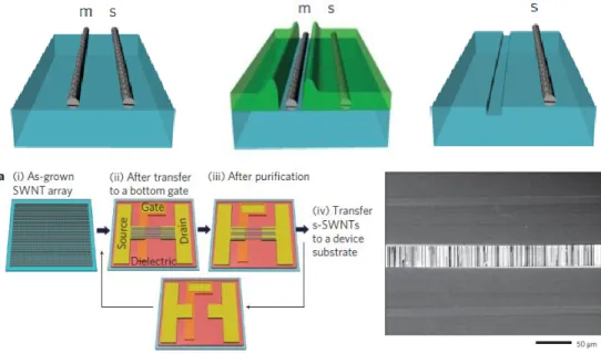
A thermo-capillary flow method is also used to obtain a higher quality sorted semiconducting SWCNT array [26]. After coating a photoresist on an unsorted SWCNT array, applying a current in the SWCNT networks generates Joule heat in the SWCNTs.
A fine thermo-capillary flow flows along the metallic nanotubes, and the photoresist around the nanotubes melts to expose the metallic nanotubes as shown in Figure 1.10. Subsequently, a high-purity semiconducting SWCNT array is obtained through an etching process of a metallic species and a development of the photoresist.
However, in the post-separation method, uniformity due to residual metallic nanotubes or debris during the purification process becomes an issue. In addition, since it is a method applied to as- grown SWCNT array, the complexity of the overall process is increased since a separate classification process is performed. For example, a transfer process may be required to apply on various substrates such as glass, plastic, metal foil, elastomer, and paper.
18
Figure 1.10 Acquisition process and result image of aligned semiconducting SWCNT array using thermo-capillary flow method.
'm' and 's' indicate metallic and semiconducting nanotubes, respectively [26].
1.3.2 First sorting out SWCNTs and deposition later
To obtain a SWCNT film composed of only metallic or semiconducting species, the method of obtaining pre-separated SWCNTs and then depositing them, rather than the post-separation method introduced in Section 1.3.1, is widely used. After dispersing the bulky SWCNT obtained through SWCNT production technology such as a CVD process into a solution, an un-sorted SWCNT dispersion can be obtained with the aid of polymers or surfactants. Subsequently, when a centrifugal separator using a strong centrifugal force of 200,000 g or more is applied, a buoyancy difference occurs according to the
19
diameter of each CNT in the dispersion, so the layers according to the thickness of the CNTs are generated. As shown in Figure 1.11 (a), this separation method is called a density gradient ultracentrifugation (DGU) method [27].
In addition, there is a method of separating SWCNTs by wrapping DNA or polymer on the outside of SWCNTs as shown in Figure 1.11 (b). Through the π-π interaction between the polymer and SWCNT, the polymer wraps around the nanotubes, and the binding strength varies depending on the chirality of the SWCNT [28].
Then, after column chromatography and checking the absorption spectra, the spectrum is clearly separated according to the chirality of the nanotubes, and a separated SWCNT solution can be obtained.
A high purity isolated SWCNT dispersion through polymer assisted sorting method can be obtained [29]. However, it is more expensive than the DGU method and has difficulty in mass production.
The solution process-based technologies for separating SWCNTs introduced above provide process flexibility by lowering the overall complexity of the SWCNT-based device fabrication process compared to the post-separation method in Section 1.3.1.
Since it is possible to supply the separated SWCNTs in solution, it is also advantageous for mass production and commercialization.
Currently, high-purity separated SWCNT dispersions are sold by NanoIntegris corporation. Using the separated semiconducting SWCNT dispersion, SWCNT-based transistors can be fabricated on various substrates at low temperatures, and many related studies have been reported to date.
20
Figure 1.11 (a) Separation of SWCNTs by density gradient ultracentrifugation method. Layers are divided according to the diameter of nanotubes [27]. (b) Separation of SWCNTs through Polymer assisted sorting method [29].
(a)
(b)
21
However, when the SWCNT network is formed through the separated SWCNT dispersion, nanotubes are usually distributed in a random direction without specific orientation. This randomly arranged nanotube network is a factor that significantly degrades the electrical performance of SWCNTs-based devices. In addition, external elements, such as surfactant, present in the dispersion may remain on the film, causing a hysteresis of the transistor or impeding electrical stability, which could interfere with normal operation. To compensate for these issues, methods of aligning SWCNTs in the solution process may be necessary, and the rinsing process to reliably remove residual nanotubes and surfactants in the deposited SWCNT film is also important.
1.4 Operation of SWCNT-TFTs
In this section, the electronic transport properties of single-walled carbon nanotubes-thin film transistors (SWCNT-TFTs) will be discussed. Unlike conventional TFTs, such as amorphous silicon or poly silicon based TFTs, the source and drain electrodes located at both ends of the channel through which a charge travels are in direct contact with the nanotube when fabricating SWCNT-based transistors. In case of fabricating the transistor using the semiconducting SWCNT dispersion mentioned in Section 1.3.2, there are numerous nanotubes in the channel, and thus plenty of junctions
22
between the nanotubes are present in the channel region. Therefore, due to these features, the operation of SWCNT-TFT is different from that of conventional TFTs.
1.4.1 SWCNT-TFTs as Schottky-barrier FETs
The process of fabricating a field effect transistor (FET) having a simple structure using semiconducting SWCNTs is as follows. After depositing the semiconducting SWCNT on an oxidized heavily doped silicon substrate using a transfer process or a solution process, depositing a source and drain metal electrode results in constituting of the transistor of the bottom gate-top contact structure as shown in Figure 1.12 (a). At the metal-nanotube contact a Schottky- contact can be expected with a Schottky-barrier of height Φ 𝐵 which means the difference between the Fermi energy level of the metal electrode and the valence band boundary of the semiconducting SWCNT as illustrated in Figure 1.12 (b) [30]. Intrinsically, SWCNT- TFTs exhibit ambipolar characteristics in vacuum or at low temperatures. In addition, this ambipolar characteristic is further emphasized when the work function of the source / drain electrodes is located near the center of the bandgap of the SWCNT. Figure 1.12 (c) is a diagram showing the situation when the current of the ambipolar transistor becomes minimum, and the transfer characteristics according to the drain voltage are illustrated in Figure 1.12 (d). When the height and width of the Schottky-barrier at the contact region between the source/drain electrodes and the SWCNT
23
is maximized, the transistor enters off-state and a minimum current flow in the channel. As shown in the graph, the off-state leakage current increases rapidly with the drain voltage, which is attributed to the size of the energy bandgap of the nanotube. The above tendency is alleviated in SWCNT-TFTs with a larger energy bandgap.
Figure 1.12 (a) A Schottky-barrier field-effect transistor with bottom gate-top contact structure including a channel composed of semiconducting SWCNT and (b) its energy band diagram in the channel. (c) Energy band diagram and (d) transfer characteristics of SWCNT-based transistors with ambipolar characteristics [30].
(a) (b)
(d) (c)
24
However, SWCNT-TFTs driven at room temperature and normal pressure exhibit hole transport characteristics rather than ambipolar transport characteristics, so operate like p-type transistors [31]. Oxygen and water molecules around the nanotube greatly inhibit the movement of electrons in the nanotube, and the concentration and movement of the hole are relatively enhanced [32].
Due to these effects, a phenomenon occurs in which the work function of the source / drain electrodes and the valence band of the nanotubes are aligned (see Figure 1.13 (a)). Differences in the work function in the source metal-nanotube contact region result in developing on a local polarization layer on the electrode-nanotube interface. The formed local polarization layer acts as the screening layer, so that the modulation effect according to the gate voltage is hardly observed.
The barrier in the contact region is suppressed and the hole is injected into the channel according to the application of the gate bias as shown in Figure 1.13 (b).
Figure 1.13 (a) Energy band diagram of SWCNT-based FET with a local polarization layer formed on the interface of the contact. (b) A gate bias suppresses of the barrier [31].
Local polarization layer Energy level pinning
(a) (b)
25
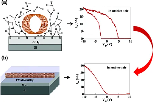
Due to the oxygen and moisture around the nanotubes and chemical functional groups such as hydroxy and silanol at the interface between the nanotubes and the gate dielectric, SWCNT- TFTs act as p-type FETs with the turn-on voltage is shifted in the positive bias. Therefore, large hysteresis occurs in the SWCNT- based transistor due to the trapping of electrons around the nanotubes (see Figure 1.14 (a)). This hysteresis can be prevented by passivation of the CNT channel with a polymer such as poly(methyl methacrylate) or polytetrafluoroethylene as illustrated in Figure 1.14 (b) [33]. The passivation layer blocks oxygen and moisture to alleviate the hysteresis phenomenon in transfer characteristics of the SWCNT-TFTs.
Figure 1.14 (a) Oxygen, water molecules and chemical functional groups around the nanotubes and interface. (b) Passivation layer surrounding SWCNTs in the channel [33].
(a)
(b)
26
1.4.2 Random network of SWCNTs
In the case of transistors composed of multiple strands of SWCNTs, not FETs composed of one strand of SWCNTs, numerous nanotubes are deposited in each direction in the channel region. The nanotubes covered in the channel region act as a kind of thin film semiconductor layer. Charge carriers pass through junctions between nanotubes in the channel region, and these junctions are elements that interfere with the movement of charges, which is like grain boundaries inside polycrystalline semiconducting materials such as single-molecule organic semiconductors or polysilicon. According to the method of generating SWCNT, the distribution pattern of SWCNT in the channel varies, and Figure 1.15 (a) illustrates the SWCNT network according to the process method. Images obtained by scanning electron microscopy (SEM) of the SWCNT network by the electrostatic precipitation (ESP), thermal precipitation (TP), press transfer from the filter (PTF), and dissolving the filter (DF) processes in [34] are shown in Figure 1.15 (a), respectively. The degree of alignment of the nanotubes in the SWCNT network varies according to each process method, and the TP-deposited SWCNTs have the highest alignment, followed by DF, PTF, and ESP. Accordingly, the number of the junctions between nanotubes in the channel is the lowest in TP-deposited SWCNTs and the mobility of TP-deposited SWCNTs-TFTs is the highest, followed by DF, PTF, and ESP (see Figure 1.15 (c)).
27
Figure 1.15 (a) SEM image of SWCNT network according to the process method. (b) Junctions between CNTs inside the channel highlighted in red. (c) Correlation between the number of junctions and mobility [34].
Figure 1.16 summarizes the electrical performance of the SWCNT-TFTs according to the generating process of SWCNTs [35].
The CVD-grown or aligned SWCNT network exhibits higher mobility than the random network. Even in a random network structure, it shows a mobility of 1 cm2/V·s or more, and a high mobility of about 100 cm2/V·s in a CVD-grown SWCNT network. However, for the samples with very high mobility, the on-off current ratio tends to decrease, which is attributed to the leakage current flowing to the metallic CNT due to the high density of CNTs and alignment in the channel.
(a) (b)
(c)
28
Figure 1.16 Mobility and on/off current ratio of the SWCNT-TFTs according to SWCNT formation method [35].
1.5 Reported SWCNT-TFTs and applications
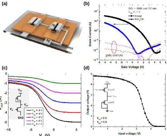
Semiconducting SWCNTs are suitable for use as active materials for transistors fabricated on flexible or stretchable substrates with high electrical performance and excellent mechanical advantages [36], [37] (see Figure 1.17). In addition, since the absorption rate of SWCNTs in the visible light region is almost non-existent, the SWCNTs can be utilized as an active channel material for a transparent transistor. As a semiconducting SWCNTs ink capable of
29
solution processing, many electronic devices based on solution processing in low temperature and normal pressure environments have been reported. Micrometer-scale SWCNT-TFTs are manufactured using semiconducting SWCNT ink by spin-coding, dipping, and inkjet printing [38]. Meanwhile, utilizing the ambipolar transport characteristics of the semiconducting SWCNT, solution- processed electrical devices such as ambipolar SWCNT-TFTs and inverters with improved hysteresis and improved electrical stability have been reported by applying a fluorine-based polymer passivation layer to SWCNT-TFTs exposed to normal temperature and pressure [39], [40]. The manufactured SWCNT-TFTs have an advantage in that the electrical properties are not significantly changed even in external physical deformation, and even on soft substrates, logic circuits based on high mobility can be implemented using SWCNTs [37].
Figure 1.17 (a) Fully printed logic gates on polyimide with SWCNTs [36]. (b) SWCNT-TFTs that operate on physical deformation of the substrate [37].
(a) (b)
30
Electrical devices manufactured by utilizing the high electrical characteristics of semiconducting SWCNTs have been reported from small units of logic gates to large-scale digital integrated circuits such as CNT-based microprocessor [41]. Especially for energy- efficient complementary metal–oxide–semiconductor (CMOS) digital logic, n-type transistors are required in addition to p-type transistors shown by the solution-processed SWCNTs. There are several methods to obtain n-type SWCNT-based transistors.
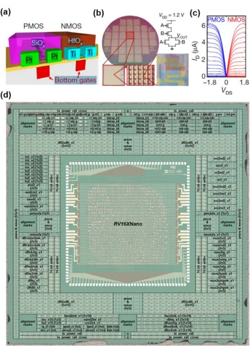
Typically, there is a method of processing a doping material in the channel or coating a separate insulating layer [42], [43]. In the CNT-based microprocessor [41], SWCNT-TFTs of complementary polarities were implemented by depositing different insulator materials on the CNT channel as illustrated in Figure 1.18 (a). About 14,000 SWCNT-TFTs in the microprocessor were implemented by using photolithography process, which is mainly used for existing silicon-based high-integration circuits and using semiconducting SWCNT ink only for active channel materials (see Figure 1.18 (d)).
If all processes other than the active formation process such as fine electrode pattern and insulating film deposition are capable of low temperature and normal pressure processes, it is expected to implement a CNT-based microprocessor on a flexible substrate rather than on a rigid silicon wafer. However, the fine pattern technology of the solution process is still insufficient compared to the photolithography process.
31
Figure 1.18 (a) CMOS-type SWCNT-TFTs, and (b) CMOS NOR gate. (c) Transfer characteristics for p- and n- type SWCNT-TFTs.
(d) Microprocessor made of over 14,000 SWCNT-based transistors on silicon wafers [41].
32
1.6 Technical points for microelectronics based on SWCNT-TFTs
There are two main points of research in major directions for practical use of microelectronics based on SWCNT-TFT. The first technical point is to control environmental effects in SWCNT-TFTs.
In ambient condition, SWCNT-TFTs have p-type unipolar transport characteristics and large positively shifted turn-on and threshold voltage. In other words, the on-off state of the transistor is not converted at the gate bias near zero voltage, and the SWCNT-TFTs operate in the depletion mode in which the transition occurs at a positive gate bias. This phenomenon tends to become more prominent in SWCNT-TFTs based on solution process. Therefore, a technique for reduction and control of the threshold voltages of SWCNT TFTs is required. It is also important to study n-type SWCNT-TFTs for complementary polarities, as used in the CNT- based microprocessors introduced in Section 1.5. In addition, securing reliability against electrical stress or research on long-term stability is also important in the future fabrication of SWCNTs-based electronic devices.
The second technical point for implementation of next- generation electronic applications based on CNT is a research on the fabrication process for highly integrated and miniaturized CNT- based electronics. The high resolution and high integration of transistors are indispensable factors for high performance, efficient
33
energy use and space efficiency of future electrical applications including display, image sensor array, logic circuits, biosensor, portable and wearable electronics. When scaling down the size of a TFT, the gate oxide thickness and channel layer thickness as well as the channel length must be scaled down. In this respect, one of the major advantages of CNTs is the nano-scaled small diameter of the tubes, which is making CNTs ideally suited for ultra-thin-film transistors. The need for low temperature and non-vacuum processes to realize electrical devices on flexible and stretchable substrates is increasing. The solution process satisfies this point and has the effect of reducing process cost thanks to the relatively simple process rather than photolithography. Currently, tens to hundreds of micrometer-scale transistors and circuits can be manufactured using solution processes such as inkjet printing, but for more high- performance devices, in-depth study is required on solution process methods that enable several micrometers or sub-micrometer scales such as electrohydrodynamic jet-printing and nanoimprint.
Additionally, research on a methodology for selectively patterning and aligning CNTs in the fine channel region of the SWNCT-TFTs to reduce leakage current and improve carrier mobility is also important.
34
1.7 Organization
The thesis is organized as follows. Chapter 2 introduces the simple technique for threshold voltage control in SWCNT-TFTs manufactured by solution process. Through this technique, the turn- on voltage and the threshold voltage shifted significantly in the positive bias direction can be compensated to some extent in the opposite direction, and conversely, the degree of the shift can be deepened, which assists in the robust design of CNT-based circuits.
Chapter 3 establishes the all E-jet printing system for SWCNT- TFTs. It includes optimization for e-jet printing of materials such as metals, insulators and semiconductors that make up transistors.
Through this printing system, it is possible to bring down the scaling effect of the overall device. Chapter 4 covers the applications such as inverters and active matrix pixel circuits in which two or more TFTs are integrated. In addition, it is possible to pursue a more highly integrated circuit design by introducing a vertically stacked structure implemented by E-jet printing. In Chapter 5, we conclude this thesis with a summary of the fabricated SWCNT-based electronic devices and discuss directions for future SWCNT-based electronics.
35
Chapter 2
Tunable Threshold Voltage in Single-walled Carbon Nanotube Thin-film Transistors
2.1 Introduction
Single-walled carbon nanotubes (SWCNTs) have great potential for various nanoelectronics from simple logic circuits to CNT-based computer thanks to excellent mechanical and electrical properties.
Significantly, random networks of SWCNTs by solution-process at low deposition temperature can enable us to realize large-area flexible electronics. Since the coexistence of metallic and semiconducting SWCNTs leads to low on/off current ratio and poor reliability in thin-film transistors (TFTs), various methods for separation of metallic and semiconducting SWCNTs have been investigated (see Section 1.3). By using density gradient ultracentrifugation method well-known for sorting mixtures of SWCNTs, as introduced in Section 1.3.2, solution-processed SWCNT-TFTs possess a large on/off current ratio (~105) with a high field-effect mobility (~30 cm2/V·s) in the linear region [44], [45]. However, large positive threshold voltage (VT) resulting in a depletion mode of operation, normally observed in solution-
36
processed SWCNT-TFTs, can be still a big challenge to realize high performance CNT-based nanoelectronics [46], [47]. Furthermore, it is a critical factor to develop molecular-scaled devices requiring low power consumption. In section 1.4, more detailed description of the operation of SWCNT-TFTs can be consulted. In order to control the VT of SWCNT-TFTs with p-type transport characteristics, several methods have been reported for depositing a passivation layer [43], using a dual gate structure [48], or applying an n-type doping material [42].
In this Chapter, we demonstrate a simple and reproducible technology to favorably tune VT in solution-processed SWCNT- TFTs employing chemical encapsulation with ammonium hydroxide (NH4OH) and nitric acid (HNO3). In addition, inverter circuits using SWCNT-TFTs with tuned VT was constructed to secure more stable inverter characteristics. We believe that this work presents an important approach toward further control of electrical characteristics in SWCNT TFTs which are adaptable to all-solution process.
37
2.2 Experimental details
2.2.1 Fabrication process for solution-processed SWCNT- TFTs
The overall device configuration of a solution-processed SWCNT- TFT is shown in Figure 2.1. Bottom gate and top contact structure were adopted. A heavily doped p-type Si wafer and a 200 nm thick thermally grown SiO2 layer were used as a gate electrode and gate dielectric, respectively. The substrates were cleaned with acetone and isopropyl alcohol in ultrasonic bath, dried with nitrogen gas, and baked in an oven at 100 ℃ for 1 hour in order to remove organic contaminants from the surface. After cleaning processes, the substrates were exposed by an ultraviolet lamp in the ozone chamber for 3 mins by drop-casting of poly-L-lysine (Sigma-Aldrich; 0.1%
(w/v) in H2O) solution ont
![Figure 1.3 (a) DNA detecting device based on SWCNT [10]. (b) Chemical Reaction Mechanism between hydrogen sulfide (H 2 S) and CNT [12]](https://thumb-ap.123doks.com/thumbv2/123dokinfo/11425768.0/27.808.154.648.491.887/figure-detecting-device-chemical-reaction-mechanism-hydrogen-sulfide.webp)
![Figure 1.5 A diagram comparing the mobility and on/off current ratio of Silicon, organic, oxide, and SWCNT [4]](https://thumb-ap.123doks.com/thumbv2/123dokinfo/11425768.0/30.808.151.668.86.482/figure-diagram-comparing-mobility-current-silicon-organic-swcnt.webp)
![Figure 1.16 Mobility and on/off current ratio of the SWCNT-TFTs according to SWCNT formation method [35]](https://thumb-ap.123doks.com/thumbv2/123dokinfo/11425768.0/51.808.210.596.87.482/figure-mobility-current-swcnt-according-swcnt-formation-method.webp)
![Figure 1.17 (a) Fully printed logic gates on polyimide with SWCNTs [36]. (b) SWCNT-TFTs that operate on physical deformation of the substrate [37]](https://thumb-ap.123doks.com/thumbv2/123dokinfo/11425768.0/52.808.157.659.676.896/figure-printed-polyimide-swcnts-operate-physical-deformation-substrate.webp)