Learning the robots for the assembly task requires a long setup time and it is difficult to take into account the geometric constraints encountered during the assembly task. The demonstration of the assembly task is recorded using the depth camera and the trajectory of the assembly part is tracked by markers. Task recognition for the assembly task is performed taking into account the geometric configuration of the assembly parts.
This paper researched the assembly task recognition method to generate the robot path by incorporating motion reference model and raw depth data. By recognizing and imitating the worker's assembly motion, generated robot path incorporates the knowledge of the worker and consideration of the geometric constraints for the assembly task.
INTRODUCTION
- B ACKGROUND
- M OTIVATION
- O BJECTIVE
- O VERVIEW
Therefore, in this thesis, we will analyze the assembly movement of the worker for teaching the robot. First, teaching the robot for the assembly task requires recognition of the assembly motion for the assembly task. First, a demonstration of the assembly task is observed through a depth camera in the process of acquiring raw depth data.
LITERATURE SURVEY
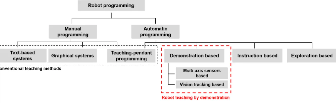
R OBOT TEACHING BY DEMONSTRATION
- Raw data acquisition
- Task recognition
- Task imitation
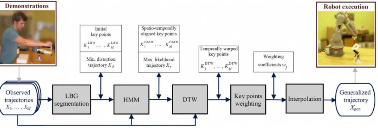
2 The robot and the F/T sensor learn how to perform the task from the demonstrator (Zhang et al., 2018). Conventional task simulation used Gaussian mixture model (GMM), Gaussian mixture regression (GMR), and hidden Markov model (HMM) for feature mapping (Tso et al., 1997). For example, they identify different types of actions during a task and learn the sequence of actions by observing a demonstration (Kyrarini et al., 2018).
C LASSIFICATION OF THE PREVIOUS RESEARCHES
Most of the task imitations using plans are related to analyzing the sequence of actions during the task and selecting the appropriate actions after task recognition. Trajectory learning for robot programming by demonstration using hidden markov model and dynamic time warping. Our thesis used external observation, complex behavior and mapping function for raw data collection, task recognition and task imitation.
Therefore, we proposed the system for analyzing the complex behavior during the assembly task, and the additional reference model called the assembly motion reference model is called to calibrate the sounds occurring during the external observation.
ASSEMBLY MOTION REFERENCE MODELS AND RAW DEPTH
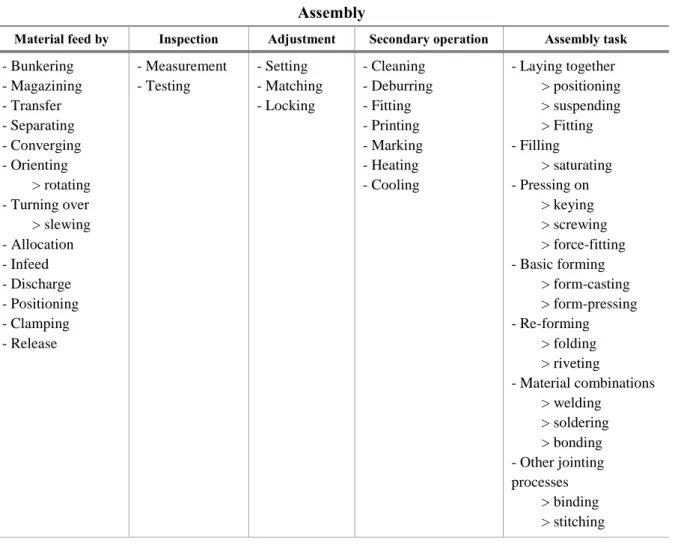
A SSEMBLY TASKS
- Assembly types
- Insert type assembly process
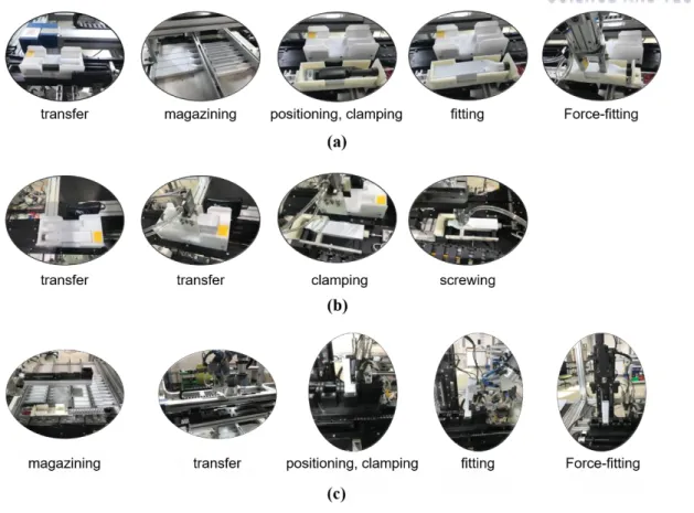
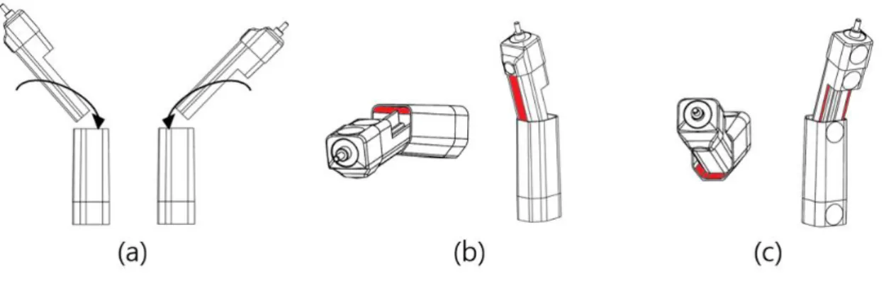
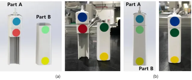
For example, the assembly process of the assembly type shown in Fig 3.1-(a) has transfer, storage, positioning, clamping, assembly and force assembly. Finally, the insert type assembly process shown in Fig 3.1-(c) has warehouse, transfer, positioning, clamping, assembly and force assembly in terms of robot assembly process. 1 (a) Activities during mounting type assembly (b) Activities during screw type assembly (c) Activities during insert type assembly.
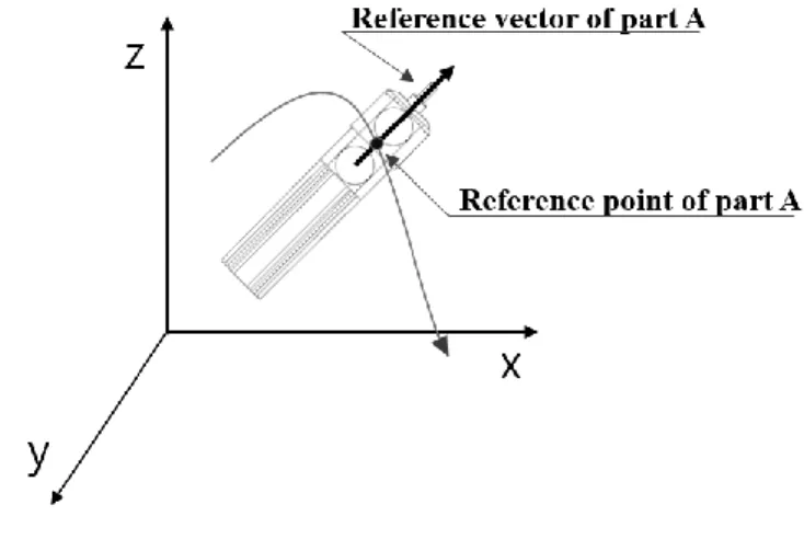
In this paper, however, the assembly tasks according to grouping and pressing on and in are discussed for the insert type assembly process. For example, work grip points between pick activities are used as a basis for generating a robot pass for other activities. The reference factors for the electric toothbrush housing used for the case study in this paper are shown in Figure 3.3, and a representation of the position and direction of the part is shown in Figure 3.4.
Reference points represent the position of the part, and reference vectors represent the orientation of the part. There can be several reference factors and they must be able to represent the state of the work during the assembly process. The center point of the two marker center points attached to the part was defined as the reference point, and the vector with the centers of the two markers was used as the reference vector.
Therefore, the state of the electrical housings of the toothbrush can be present using reference points and vectors in a three-dimensional space.
A SSEMBLY MOTION REFERENCE MODELS
- Assembly part registration
- Assembly sequence and constraints
- Reference models for assembly motions
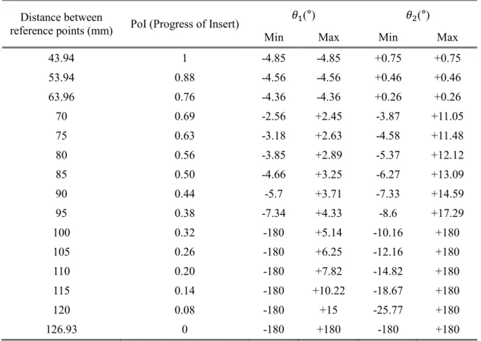
The geometric assembly status of the assembly parts can be represented by the relationship between the reference points and vectors, as shown in Figure 3.5. The reference value representing the progress of the insert is called PoI (Progress of Insert), and the distance between reference points can be used to indicate the progress of the assembly. 𝐷𝑠: distance between reference points at the start of the insertion task 𝐷𝑐: distance between current reference points.
The distance between the points at the beginning of the insert and the distance between the points at the end of the insert for the electric toothbrush are shown in Figure 3.7. The start of the inset is defined so that overlapping parts are created, and the end of the inset is defined so that the distance between the reference points is minimal. The presentation of the geometric assembly state of the assembly task can be simplified by considering the geometric constraints.
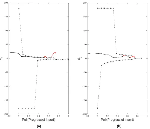
Geometric assembly constraints in assembly tasks can be varied and complex depending on the assembly method and the shape of the parts. Therefore, during the insertion, trajectory of the reference vector is only taken into account in the single plane. Geometric constraints limit the degree of freedom of the reference vector during the assembly task.
As shown in Table 3.3, the ranges of 𝜃1 and 𝜃2 are given according to the distance between the reference points and the PoI.
D EPTH DATA ACQUISITION OF ASSEMBLY MOTIONS
- Trajectory data processing and decomposition
- Trajectory registration for assembly motions
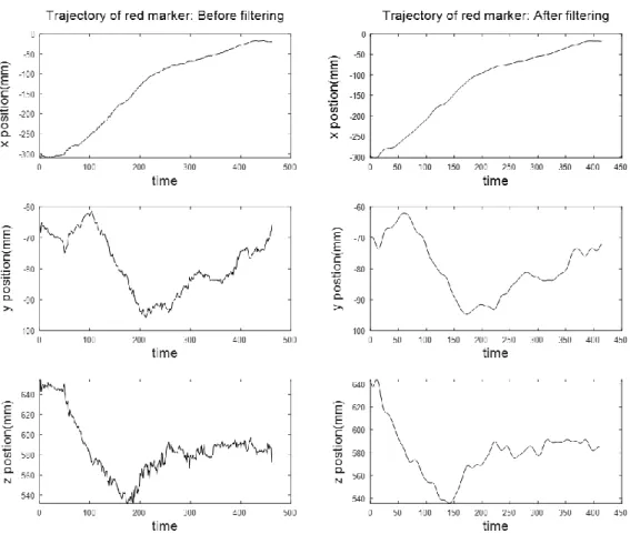
The raw depth data for the yellow marker during the fitting task is shown in Fig. 3.15. The raw depth data for the red, blue, and green producer is provided in Appendix B. There is one more step to generate subject trajectories using raw depth data.
The raw depth data from the depth camera is from the camera coordinate. Part trajectories are calculated using the newly created marker depth data. The trajectories and orientation of the part during the assembly process represented by reference points and vectors are shown in Fig. 3.17.
Since the assembly task of the electric toothbrush is performed with two parts, the trajectory of the two parts is shown in Fig 3.17, and the unit vectors of the newly generated coordinate system are also described in the Figure. To define the assembly state, decomposition of the trajectory along the distance is necessary to find out the assembly task division under the assembly process. However, trajectory includes all the movement performed by demonstrator during the assembly task, such as hand tremors and incorrect attempts.
The trajectory of the assembly task is shown in Fig 3.20, and distance between the reference points, 𝜃1 and 𝜃2 is presented in Fig 3.21 in specific assembly condition.
INTUITIVE ROBOT TEACHING FOR INSERT ASSEMBLY
R OBOT TASK PLANNING
- Calibration of the registered trajectories based on motion reference models
- Extraction of waypoints using a Gaussian Mixture Model
- Robot path reproduction for assembly task
- Robot path verification via simulation
Trajectory calibration using the reference motion model is shown in Figure 4.5 in 2D and Figure 4.6 in 3D. The red trajectory in Figure 4.5 and Figure 4.6 is the irregular data collected from the depth camera. Five sets of registered trajectory are used for calibration as shown in Figure 4.7.
Assembly motion reference models show the possible ranges for 𝜃1 and 𝜃2 according to the POI. 9 (a) Calibrated five recorded trajectories (b) Gaussian mixture model applied recorded trajectories (c) Gaussian mixture regression model of the recorded trajectories. The 'x'-marked points in Fig. 4.9-(b) are the selected key points and the PoI value of the key points is selected.
The x-y coordinate system of the generated robot path is generated on the plane shown in Fig. 3.8. The x-y coordinate system is based on the reference point of the base part as the origin, and the x-axis is defined to be parallel to the plane when the base part is placed on the plane as shown in fig. 4.10. For verification of the generated robot path, interference detection of the parts is performed for the 14 points as shown in Fig. 4.13.
The 14th point has the interference of 0.01𝑚𝑚3 due to the marker and for the other points as shown in Fig 4.14, there was no interference observed between the parts.
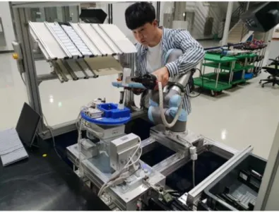
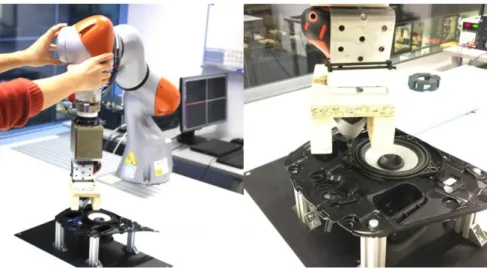
E XPERIMENTS
- Experiment setup
- Experiment result
- Discussion
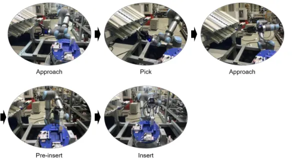
The robot path was created by direct teaching methods and it is illustrated in Fig 4.16. Second case illustrated in Fig 4.17 was performed with created robot path similar to the robot path shown in Fig 4.12. The robot path is created to include the trend of the robot path shown in Fig 4.12 using direct teaching methods.
Therefore, the robot path shown in Fig 4.12 could not be executed correctly in this experiment. In case 2, the pre-insertion of the robot proceeds in an oblique direction as shown in Fig 4.17, and the pre-insertion of case 1 proceeds in a linear direction. The assembly test result was recorded with success, crash success and failure, and the test result is shown in Table 4.1.
The part on the magazine does not always hold the same position, so the grip point of the part is always different. Linear directional assembly has the potential to cause collision during pre-insertion because the assembly tolerance is small compared to oblique directional assembly. Oblique directional assembly maximizes joint tolerance during pre-insertion as shown in Fig. 4.18.
Oblique directional assembly shown in Fig 4.18-(b) has greater assembly tolerance than linear directional assembly shown in Fig 4.18-(a).
CONCLUSION AND FUTURE RESEARCH
By recognizing and mimicking the worker's assembly motion for robot learning, the generated robot trajectory incorporates the worker's knowledge and considerations of the geometric constraints of the assembly task. Therefore, the interface for the raw depth data acquisition requires improvement to minimize the error factor that occurred during the observation. By applying position estimation algorithms such as ICP to generate the trajectory of the part, the reliability of the acquired trajectory can be improved.
The data acquisition systems that use multi-depth cameras can also improve the reliability of the data. Trajectory keypoint extraction can be performed by using different models, such as hidden markov model and Bayesian networks. The five sets of the trajectory, which are used to extract key points in this thesis, also show the different trend according to a particular section.
By weighting the data according to their importance, the reliability of the key points will be improved. The classification of activities during the assembly process is performed using the distance between the reference points. Therefore, more general and more precise classification of activities is possible by improving and applying such methods as described in the literature review in this thesis.
In Proceedings of the seventh annual ACM/IEEE international conference on Human-Robot Interaction (pp. 391-398).