With the rapid growth of demand for portable electronics, electric vehicles (EVs) with high energy density and mechanical flexibility, the importance of rechargeable power sources is increasing. Among a variety of rechargeable systems, lithium-ion batteries (LIBs) are the most suitable energy storage system. It is well known that the higher energy density of LIBs comes from the higher storage capacity value of electrode active materials and electrode architecture.
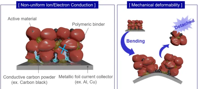
First, the random stacking of electrode components such as active materials, conductive additives, and polymeric binders causes irregular electron/ion transport path through the thickness direction. Third, the non-faradaic materials such as metallic current collector, conductive additives and polymeric binders account for a large part of the total electrode mass, resulting in lower areal capacities and energy densities of the LIBs. To realize the aforementioned goal, our primary interest is focused on the design/synthesis of multifunctional polymer fibrils and also HM electrode architecture along with proper selection of target electrode active materials.
In addition, a lot of attention should also be paid to the production processes and the optimization of the manufacturing conditions of HM electrodes. In order to explore the potential applicability of HM electrodes for LIBs, comprehensive structural/electrochemical characterizations are carried out, with special emphasis on 3D-lattice, bicontinuous ion/electronic conduction pathways.
Introduction
Overview of rechargeable power sources
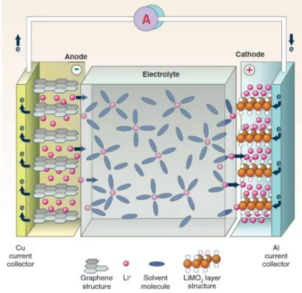
The ever-increasing popularization of high-performance portable electronics, flexible/wearable devices, electric vehicles (EVs), and grid-scale energy storage systems (ESSs) has led to a relentless pursuit of advanced power sources with high energy density, electrochemical sustainability, and mechanical flexibility. Rechargeable (or secondary) batteries are among the most successful power sources that can repeatedly generate electricity from stored material and convert reverse electrical energy into chemical energy.[1,2] A typical rechargeable battery consists of main components such as cathode, anode, separator , electrolytes. The basic principle of the rechargeable battery is based on the redox reaction (i.e. reduction and oxidation) of the electrode.
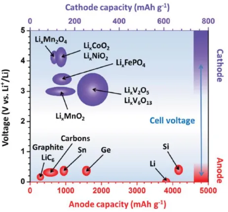
Generally, the positive electrode is called the cathode and the negative electrode is called the anode based on the discharge process. The redox reaction of the cathode and anode takes place relative to the reduction potential of the active materials of the electrode. The potential difference between the two electrode redox reactions determines the working voltage of the battery, while the capacity (given in Ah kg-1) depends on the number of electrons and the molecular weight of the electrode's active materials.
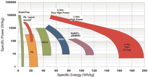
For example, the lead-acid battery is used for electric scooters, where weight is less important. This is why lithium-ion batteries are particularly suitable for a variety of applications, such as portable devices and electric vehicles.[4]
Principle of lithium-ion batteries
Moreover, the unique heteronanoma structure of the HM OLO cathode was not damaged after the bending cycle test (Figure 2.10c). MWCNT is an indirect evidence to prove the easy accessibility of HM OLO cathode electrolyte. The architectural excellence (in terms of ion/electron transport phenomena) of the HM OLO cathode allowed significant improvement in cycling performance with fast charge/discharge current density = 5.0 C/5.0 C (Figure 2.14a and 2.14b).
The cycling performance of the multi-stack HM OLO cathodes was examined at the charge/discharge current density of 0.5 C/0.5 C under the voltage range 2.0 - 4.7 V (Figure 2.17b). To produce the active Si layer (middle), Si nanoparticles (Alfa Aesar, with an average diameter of 100 nm) were mixed with SWCNTs (Tuball) and PEDOT:PSS (Clevios, PH1000) in water/isopropyl alcohol (IPA w/w )) solvent. The electrochemical performance of the nanomat electrodes was characterized using 2032-type coin cells (= nanomat electrode/polyethylene (PE) spacer (20 μm thickness, Toray-ton)/Li metal).
A schematic representation showing the step-by-step fabrication of the nanomatte Si anode is shown in Figure 2.26. This improvement in electrode capacity is a result of the architectural uniqueness of the nanomatte Si anode. The superior rate performance of the nanomat Si anode was attributed to the heteronanomat-enabled, 3D bicontinuous ion/electron transport channels.
The through-thickness overvoltage distribution of Si anodes was quantitatively investigated as a function of SOC (Figure 2.35a). The cycle capacity (expressed as mAh gAnode-1) of the nanomat Si anode was studied at charge/discharge current densities of 0.2 C/0.2 C (Figure 2.36). The electrochemical performance of the nanomat OLO cathode was investigated using a coin (OLO cathode/PE separator/Li metal anode).
A cross-sectional SEM image of the all-nanomat LIB cell (Si anode/Al2O3 separator/OLO cathode) is shown in Figure 2.50a. The cycling performance (expressed as mAh gcell-1) of the all-nanomat full cell was examined at a charge/discharge current density of 0.5 C/0.5 C (Figure 2.51d).
Lithium-ion battery materials (LIBs)
- Cathodes active materials
- Anode active materials
- Separators
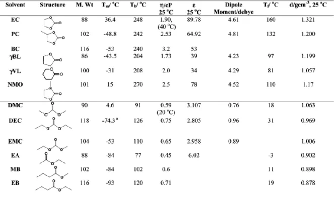
- Electrolytes
- Electrode components
Research objective
- Limitations of the conventional electrode architecture
- Research progress in electrode architecture for LIBs
- Strategies
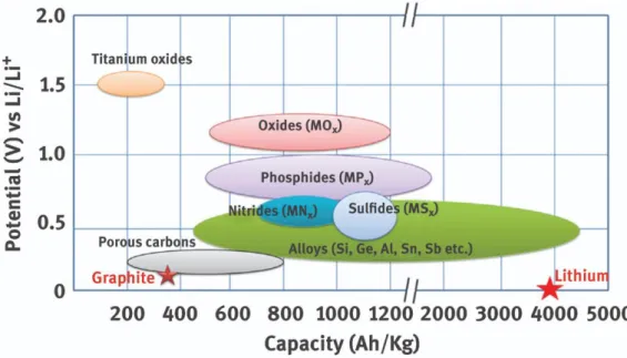
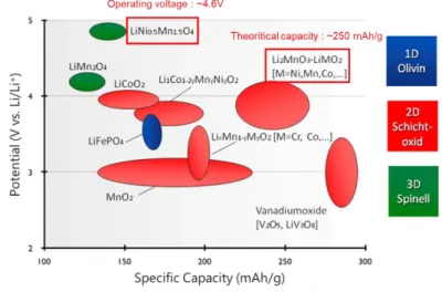
In other words, the greater the capacity of the active material and the greater the difference between cathode and anode operating potentials, the better (Figure 1.5).[17] Therefore, numerous studies focus on electrode active materials gradually. However, the active electrode material is mixed with the binder and conductive material to form a typical electrode, so the structure and efficiency of the ion/electron path in the electrode is absolutely a key factor controlling the energy density. Due to the flat and smooth surface of the metallic pantograph, a very weak adhesion and limited contact between the electrode materials and the pantograph also results in a weak mechanical deformation.
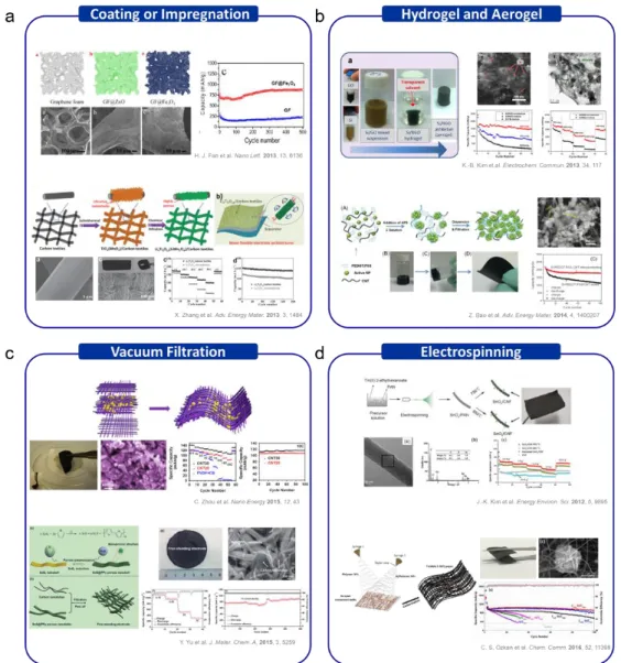
These 3D substrates act as a flexible, strong current collector that easily allows fast ion/electron migrations (Figure 1.7a). One of the popular approaches to form a uniform conductive network in the electrode is vacuum filtration. They generally use mixed suspension solutions of electrically conductive materials with active materials to improve the speed and cycling properties (Figure 1.7c).
To improve the electrochemical properties, free-standing 3D mat electrode consisting of active material/carbon fiber produced by electrospinning (Figure 1.7d). 27,28] But the active material load is limited by covering the surface of the carbon mat.
One-dimensional building elements-intermingled heteronanomats as a platform
- Introduction
- Experimental section
- Alchitectural design and fabrication of HM cathode
- Structural/physicochemical characterization of HM cathodes
- Electrochemical performance of HM cathodes
- Result and discussion
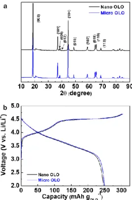
- Structural and physicochemical proeprties of HM OLO cathode
- Electrochemical properties of HM OLO cathodes
- Ultrathick HM OLO cathodes for high capacity
- Physicochemical and electrochemical properties of HM LNMO cathodes
- Conclusion
- References
Each layer of the nanomat Si anode was fabricated by simultaneous electrospinning and electrospraying through two different nozzles. The thickness change (Δt = thickness (after 100 cycles) – thickness (before cycles)) of the Si anodes was recorded. Figure 2.44 shows a conceptual representation showing the structural uniqueness of the nanomat OLO cathode, alongside a photograph showing its mechanical flexibility.
All-nanomat lithium-ion batteries: A new cell architecture platform for ultrahigh energy
- Introduction
- Experimental section
- Design and fabrication of nanomat Si anodes
- Fabrication of nanomat OLO cathodes incorporating rambutan-shaped
- Fabrication of nanomat A 2 O 3 separator
- Structural/physicochemical characterization of the nanomat electrodes
- Electrochemical characterization of nanomat electrodes and all-nanomat full
- Result and discussion
- Structural uniqueness and electrochemical superiority of nanomat Si anodes 41
- All-nanomat (Si anode/Al 2 O 3 separator/OLO cathode) full cells for ultrahigh
- Conclusion
- Reference
Carbon nanotube-cored cobalt porphyrin as a one-dimensional nanohybrid strategy for
- Introduction
- Experimental section
- Synthesis of CoTCPP
- Dispersion of the MWCNTs in aqueous solutions with various dispersing
- Preparation of the CC-nanohybrids
- Fabrication of the slurry-cast and nanomat CC-nanohybrid anode sheets
- Physicochemical and structural characterization
- Electrochemical characterization
- Theoretical model systems
- Result and discussion
- Preparation and structural characterization of the CC-nanohybrids
- Electrochemical superiority of the CC-nanohybrids over pristine CoTCPP - 76
- Conclusion
- Reference
Moreover, they are intrigued by the 1D structure of the CC nanohybrid, and its fully fibrous nanomat anode sheets. Then, 150 mL of 1 M aqueous HCl solution was added to the mixture solution, which resulted in the precipitation of the powders. The electrolyte wettability of the slurry cast and nanomat anode plates was evaluated by measuring the height of electrolyte immersion.
Cell CV profiles were obtained using a potentiostat/galvanostat (Bio-Logic VSP classic). The step-by-step preparation of CC-nanohybrids is schematically illustrated in Figure 2.57, along with photographs of the products obtained at each step. The structural specificity of the CC nanohybrids was further elucidated using Raman and XPS methods.
The Raman spectrum (Figure 2.62c, blue line) of the CC nanohybrids showed the overlapping characteristic peaks assigned to CoTCPP (red line) and MWCNTs (black line). The resulting anode showed the structural disorder due to the poor dispersion state of the MWCNTs. The analysis of the associated correct equivalent circuit model[43] showed that the charge transfer resistance (RCT) of the CC nanohybrid anode (~51 Ω) was remarkably lower than that of the pristine CoTCPP anode (~156 Ω), demonstrating structural advantage of the CC nanohybrid.
Intrigued by the 1D structure of the CC nanohybrids, fully fibrous nanomatanode sheets were fabricated by simultaneous electrospraying (for CC nanohybrids and SWCNTs) and electrospinning (for PAN) processes. The amount of CC nanohybrid in the nanomat anode sheet was estimated to be 47.6 wt% based on the ICP-MS analysis (Table 2.2). The differential capacitance (dQ/dV) analysis of the nanomat anode plate showed clear reduction peaks at about 0.6 V (Figure 2.69a), which were not clearly observed in the slurry cast anode plate (Figure 2.69b).
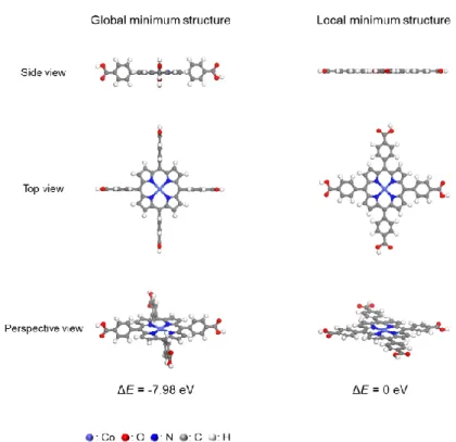
To better elucidate the intriguing electrochemical behavior of the nanomat anode plate, the lithium storage behavior of CoTCPP was theoretically investigated. Compared to the slurry-cast anode plate (black line), a significantly higher gravimetric capacity was observed at the nanomat anode plate (red line), emphasizing the beneficial effect of the metallic foil current collector-free architecture. The above electrochemical performance of the nanomat anode plate was compared with the previously reported high capacity LIB anode plates (Table 2.5).
The chemical/structural uniqueness of the CC nanohybrids facilitated electron transfer and electrolyte accessibility, thereby significantly improving the redox kinetics compared to the pristine CoTCPP. Fascinated by the 1D structure of the CC nanohybrid, the fully fibrous nanomat anode sheets without the metallic current collectors were fabricated using simultaneous electrospray/electrospinning processes.