However, there are major obstacles to the practical application of IT-SOFCs, including poor oxide-ion conductivity and poor catalytic activity of the conventional cathodes traced from the reduced temperature.
Introduction
Scope of the Thesis
In chapter 3, the effect of increasing n in Lan+1NinO3n+1(n = 1, 2 and 3)-YSZ compounds prepared by the infiltration method was investigated in terms of structures, electrical characteristics and electrochemical properties. In Chapter 4, the effects of Fe on the microstructure, electrical properties, and electrochemical performance for cation-ordered perovskite oxide prepared by the infiltration method are discussed.
General Introduction
- The Basis of Fuel Cell
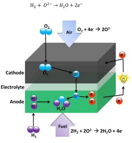
- Basic Operating Principle of SOFCs
- The Advantages and Disadvantages of SOFCs
Additionally, the SOFC can be powered by reforming heavier hydrocarbons such as gasoline, diesel, jet fuel (JP-8) or biofuels. As a result, fuel cells can be easily installed near places of use, such as urban residential areas.
Theoretical Background
- The thermodynamic potential of SOFCs
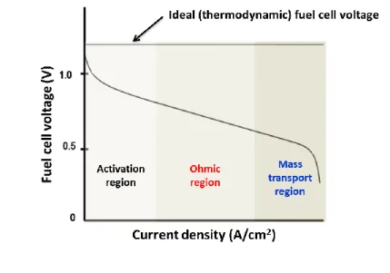
- Fuel cell performance
- Fuel cell Efficiency
- Fundamental Principle of Electrochemical Reaction Mechanisms
- Charge and Mass Transport Process
The overall response of SOFCs is given as. the difference in the Gibbs free energy of formation of ∆𝐺 during the reaction can be given as. At the same time, products must be constantly removed in order to avoid "suffocation" of the cell.
Materials in solid oxide fuel cells
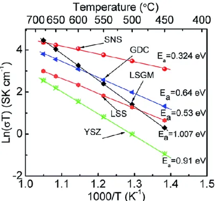
- Status of Electrolyte
- Status of Cathode
- Status of Anode
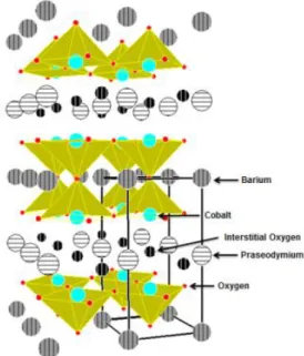
Thermodynamic properties of complex oxides in La–Ni–. Electrochemical and thermodynamic characterization of PrBaCo2-xFexO5+. x = 0, 0.5 and 1) infiltrated into the yttria-stabilized zirconium scaffold as cathode for SOFCs. According to the TGA and iodometric titration data in Figure 6.4(b), the oxygen content of LBSCO and LBCO are 5.73 and 5.5817, respectively, at 650 oC, indicating that LBSCO has a higher concentration of mobile interstitial oxygen than that of LBCO . 3 Sihyuk Choi, Seonhye Park, Jeeyoung Shin and Guntae Kim* “Effect of Calcium Doping on Performance and Stability Improvement in Layered Perovskite Cathode for Medium Temperature Solid Oxide Fuel Cells” (2014) J.
18 Sihyuk Choi, Jeeyoung Shin, Guntae Kim* “Electrochemical and thermodynamic characterization of PrBaCo2-xFexO5+ (x infiltrated into yttria stabilized zirconia scaffold as solid oxide fuel cell cathodes” J.
Experimental
Cell Fabrication
Basic Characterizations
- Structural Analysis
- Iodometric Titration and Thermal Analysis
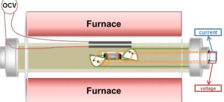
- Electrical and Electrochemical Analysis
- Redox property and Oxygen non-stoichiometric Analysis
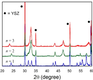
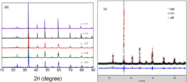
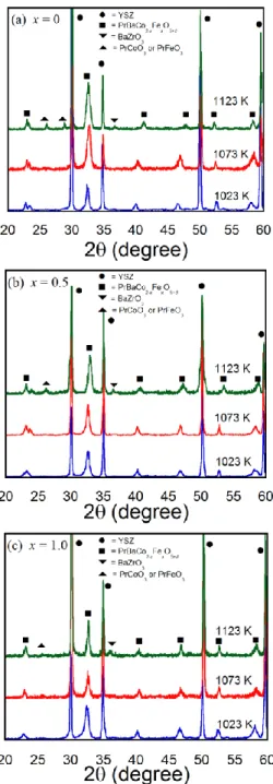
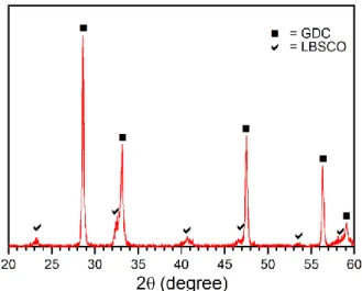
The phase identification of the materials at room temperature was performed by X-ray powder diffraction (XRD) (Rigaku diffractometer, Cu Kα radiation) with a scan rate of 0.5 o min-1 in the 2θ range from 20 o to 60 o . The thermal expansion coefficient (TEC) values of the samples were measured from 100 to 800 oC with a heating/cooling rate of 5 oC min-1.
Introduction
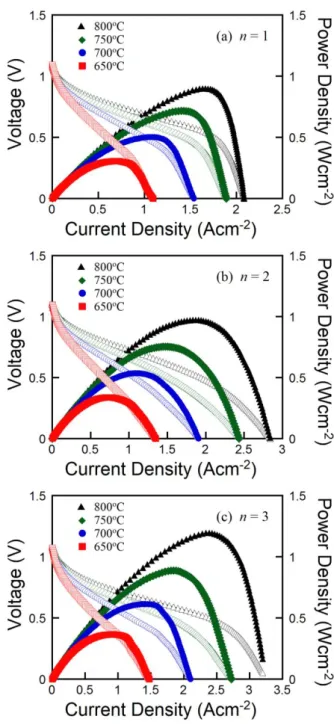
To our knowledge, there have been no reported studies on the single cell electrochemical performance and electrical characteristics of Lan+1NinO3n+1 oxides in composite form. The electrochemical performances of a Ni-YSZ anode-supported cell using Lan+1NinO3n+1-YSZ composites (n = 1, 2 and 3) as cathode, prepared by infiltration into porous YSZ, are evaluated.
Experimental
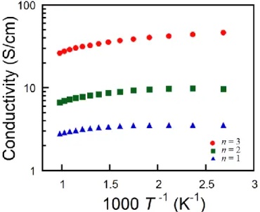
After synthesizing the Ni-YSZ anode-supported cells, Lan+1NinO3n+1 solutions (n = 1, 2 and 3) were added to the porous backbone of the YSZ cathode by the infiltration method, which was repeated until the loading reached 45 %wt. . The electrical conductivity of the Lan+1NinO3n+1-YSZ composite plates (n = 1, 2 and 3) were measured by a four-terminal DC arrangement in air.
Results and discussions
The electrical conductivity of the composition La2NiO4-YSZ (n = 1) and La3Ni2O7-YSZ (n = 2) did not show significant changes in the low temperature region (T<300oC) and then decreased with increasing temperature (300 oC< T<750 oC). The electrochemical impedance spectra of NiO-YSZ/YSZ/Lan+1NinO3n+1-YSZ composites (n = 1, 2 and 3) corresponding to the I-V polarization curve under 800 mV at 750 oC are shown in Figure 3.9.
Conclusion
However, there are major obstacles to the practical use of IT-SOFCs, including poor oxide ion conductivity and poor catalytic activity of the conventional cathodes that trace from the reduced temperature.5-7 The development of a highly stable cathode material with both high oxide - ionic conduction and electrocatalytic activity can therefore be an important step towards the commercialization of IT-SOFCs. When the electronic conductivity in the electrolyte is negligible, the cathodic polarization resistance can be adequately approximated by the diameter of the impedance loop or the difference between the high-frequency and low-frequency sections at the real axis.38 As shown in Figure 8.5(a), the ASR value of PBSCaCO-GDC (0.079 cm2) is lower than that of PBSCO-GDC (0.093 cm2) at 600 oC, based on a GDC electrolyte; this can be explained by the higher electrical conductivity associated.
Experimental
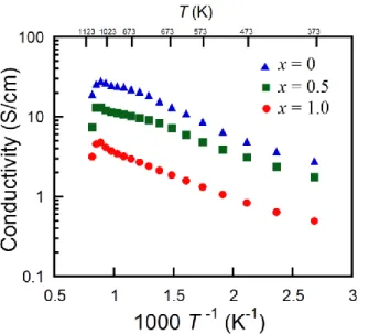
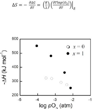
The redox properties of the 42 wt% PrBaCo2-xFexO5+-YSZ composites were measured using coulometric titration as a function of oxygen partial pressure, pO2. The samples for these experiments were prepared by infiltration of the aqueous nitrate salts of PrBaCo2-xFexO5+ into a porous YSZ plate.
Results and discussions
However, the electrical conductivities of the bulk material28 are reported to show an inflection point at a lower temperature compared to PrBaCo2-xFexO5+-YSZ composites. The electrical conductivities of the PBCO-YSZ composite range from 18 to 23 S cm-1 at different pO2, but the electrical conductivities of.
Conclusion
Synthesis, characterization and evaluation of PrBaCo2−xFexO5+δ as cathodes for medium temperature solid oxide fuel cells. Solid oxide fuel cell cathodes prepared by infiltration of LaNi0.6Fe0.4O3 and La0.91Sr0.09Ni0.6Fe0.4O3 into porous yttria-stabilized zirconia.
Chemical compatibility, redox behavior, and electrochemical performance of
Experimental
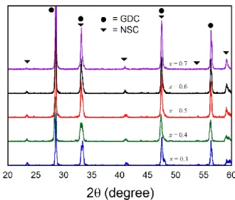
The cathode slurries were painted symmetrically on both surfaces of the dense GDC electrolyte and then sintered at 900 oC for 4 hours under an air atmosphere. Electrical conductivity of the NSC cathodes was measured by a four-terminal DC arrangement in air.
Results and discussions
The electrical conductivity of NSC cathodes is shown in Figure 5.5 for a temperature range of 100-900 oC in air. The combined effect of electronic and ionic compensation appears to determine electrical conductivity.10.
Conclusion
Comparison of Ln0.6Sr0.4CoO3−δ (Ln = La, Pr, Nd, Sm and Gd) as cathode materials for medium-temperature solid oxide fuel cells. A comprehensive microscale model for transport and reaction in intermediate-temperature solid oxide fuel cells.
Experimental
For the measurement of electrical conductivity, the precalcined powder is pressed into pellets at 5 MPa and sintered in air at 1000 oC for 12 hours. The GDC powder was pressed into pellets and then sintered at 1350 oC for 4 h in air to obtain a dense electrolyte substrate whose thickness was ~1 mm.
Results and discussions
The typical impedance spectra and Arrhenius plot of the LBSCO-GDC cathode on the GDC electrolyte are shown in Figure 6.5. The Arrhenius plot of the ASR value for the LBSCO-GDC cathode on the GDC electrolyte is shown in Figure 6.5(b).
Conclusion
Characterization of cation-ordered perovskite oxide LaBaCo2O5+δ as cathode of medium-temperature solid oxide fuel cells. Optimization of Sr content in layered SmBa1–xSrxCo2O5+δ perovskite cathodes for medium-temperature solid oxide fuel cells.
Introduction
Thus, the properties can be adjusted according to the type and amount of the corresponding ionic substitution. Here we report the synergistic effect of co-doping (Sr at the A-site and Fe at the B-site) in a cation-ordered double perovskite, LnBaCo2O5+, to create crystal channels for fast oxygen ion diffusion and rapid surface oxygen exchange while maintaining electrolyte compatibility for IT-SOFC and durability under operating conditions.
Experimental
Current and voltage were controlled/measured using a potentiostat (BioLogic) in the temperature range of 100 to 750 oC with an interval of 50 oC. Impedance spectra were recorded under OCV in a frequency range of 1 mHz to 500 kHz with AC excitation of 10 mA in the temperature range of 500~650 oC.
Results and discussions
DFT calculations indicate that the most likely elementary pathway for the ORR on the PBSCFO cathode can be described as follows (Figure 7.4b and Table 7.4): (1) adsorption and dissociation of molecular O2 on an oxygen vacancy near a Co -ion, (2) ) incorporation of the dissociated oxygen ions into the pore channels; (3) diffusion of the oxygen ions through the pore channels (mass diffusion), and (4) combination of the oxygen ions with oxygen vacancies in the GDC electrolyte. DFT calculations indicate that the most probable elementary pathway for the ORR on the PBSCFO cathode can be described as follows (Figure 7.4b):. 1) adsorption and dissociation of molecular O2 on an oxygen vacancy near a Co ion, (2) incorporation of the dissociated oxygen ions into the pore channels; (3) diffusion of the oxygen ions through the pore channels (mass diffusion), and (4) combination of the oxygen ions with oxygen vacancies in the GDC electrolyte.
Conclusion
Electrochemical investigation of composite cathodes with SmBa0.5Sr0.5Co2O5+δ cathodes for solid oxide fuel cells operating at medium temperatures. Rational design of new cathode materials in solid oxide fuel cells using first-principles simulations.
The effect of calcium doping on improvement of performance and durability in
Experimental
The calcined powders were then dry pressed into pellets at 5 MPa and sintered in air at 1100 oC for 12 hours. The cathode slurry was painted symmetrically on both surfaces of the dense GDC electrolyte and then sintered at 1000 oC for 4 hours.
Results and discussions
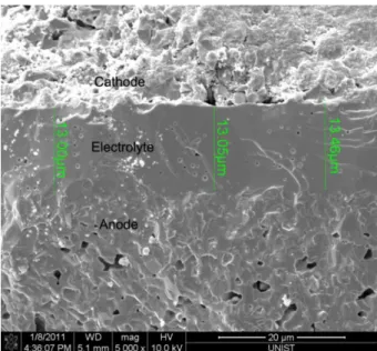
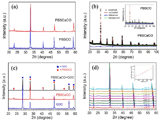
As shown in Figures 8.2(b) and (c), the cross-sectional morphology of PBSCO–GDC and PBSCaCO-GDC indicates homogeneously dispersed particles and relatively small grain size with good connectivity between the electrode and electrolyte, which helps effective gas diffusion. The pO2 dependence of the electrical conductivity of PBSCO and PBSCaCO at 700 oC is measured simultaneously and the results are shown in Figure 8.4(b).
Conclusion
Stability, chemical compatibility and electrochemical performance of GdBaCo2O5+x layered perovskite as a cathode for medium temperature solid oxide fuel cells. Novel layered perovskite oxide PrBaCuCoO5+δ as a potential cathode for medium-temperature solid oxide fuel cells.
Highly Efficient and Redox Stable Layered Perovskite Ceramic Anode for SOFC
Experimental
The potential across the membrane is given by the ratio between p(O2) outside and inside the cell according to the Nernst equation. To prepare the anode slurry, disordered Pr0.5Ba0.5MnO3 was mixed with an organic binder V-006 (1:2 weight ratio).
Results and discussions
Figures 9.4d and e show that ordered PBMO particles have a rough surface morphology with many facets and defects, as represented by red arrows in Figure 9.4e. The PBMO with PBMO catalyst shows stable power output without visible degradation for 50 hours in Figure 9.10.
Conclusion
13 Seonyoung Yoo, Sihyuk Choi, Junyoung Kim, Jeeyoung Shin, Guntae Kim* “Research on Layered Perovskite Type NdBa1-xSrxCo2O5+ (x and 1.0) Cathodes for Medium Temperature Solid Oxide Fuel Cells” Electrochim. 17 Seonhye Park, Sihyuk Choi, Jeeyoung Shin, Guntae Kim* “Electrochemical investigation of doping effect of strontium on high-performance Pr1-xSrxCoO3-(x and 0.7) cathode for medium-temperature solid oxide fuel cells” J.