However, most of the previous works failed to build a reliable drug testing platform, as the largely exploited material - polydimethylsiloxane (PDMS) - absorbs even small hydrophobic molecules, such as anti-cancer drugs. 5% GLYMO treated PETE membrane is sandwiched between two layers of air plasma treated PMMA substrates. A)-(I) SEM images of the porous PETE membrane in bare state, air plasma treated and GLYMO treated.
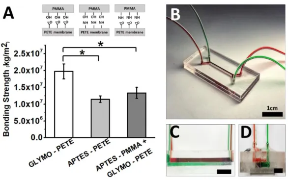
-IR analysis of (A) GLYMO-treated PETE membrane and (B) APTES-treated PETE membrane compared to air plasma-treated PETE membrane, respectively. The bond strength between PMMA and PETE membrane was measured in terms of shear stress. Plan view schematic representations of the microfluidic channels and PETE membranes assembled with PMMA and PDMS.
The two inset panels at the top and right sides of the images depict the longitudinal and lateral cross-sectional views of the cells grown on the membrane in the PMMA and PDMS devices, respectively. The fluorescence intensity of the PETE membrane (bottom panel of A) was measured after the channel was washed out with a buffer solution to remove residual rhodamine B dyes in the channel. B) The quantitative comparison of rhodamine B absorbed in the PDMS channel, the PMMA channel and the PETE membrane, respectively.
List of table
Introduction
Over the past decades, the development and testing phase of the drug pipeline has been severely limited due to the strict regulation and expensive production costs, resulting in very few drugs entering the market each year1. Despite many efforts to outsource analytical tests and clinical trials, keeping up with such a huge demand is still extremely challenging to this day. Many have attempted to construct drug testing models using microfluidic approaches and achieved some success.
Acetaminophen (AP) was introduced into the device and the corresponding viability of human liver cancer cells (HepG2) on the lower channel was then collected and analyzed4. Although instrumental in analyzing the toxic effect of drugs, most of these test models are unreliable due to the device materials. Among many others, poly(dimethylsiloxane) (PDMS) is the most widely used polymer for the fabrication of microfluidic chips due to the advantages it offers such as easy sealing and optical transparency6.
To this end, many researchers have used thermoplastic materials such as polymethyl methacrylate (PMMA), polycarbonate (PC), and cyclic olefin copolymer (COC) as an alternative to conventional silicon or glass material. These resins exhibit rigid mechanical properties, high compatibility with electrophoresis, and strong resistance to chemicals and solvents, making them better suited for drug cytotoxicity testing compared to the PDMS-based microfluidic setting. To construct a fully compartmentalized microfluidic device from thermoplastic resin, several bonding methods have been previously explored.
On the other hand, solvent-assisted thermal bonding allows preserving the channel structure since the bonding occurs at a much lower temperature. This is because the chemical linker acts as a plasticizer to lower the glass transition temperature on the surface of the thermoplastic. We further validated the efficacy of our model by determining the viability of human lung cancer cells when exposed to the anticancer drug vincristine.
Our proposed method is promising to lower the entry barrier for prototyping microfluidic chips for drug cytotoxicity assays.
Materials and method
- Microfluidic channel design and fabrication
- Cell culture
- Bonding strength measurement
To address these unmet challenges, we developed a simple binding method of PMMA to porous PETE membrane using coupling reagent GLYMO for a compartmental drug testing model. Hydrophobic track-etched PETE membrane (1 μm pore size, SterliTech, Kent, WA, USA) was cut to fit the PMMA substrates (width x length; 3.5 cm x 3.5 cm) and then rinsed with IPA, DI water before gently blowing. dried with nitrogen gas under pressure. PETE membrane was oxidized with air plasma treatment (80 W, 50 kHz Cute-1MPR, Femto Science, Gyeonggido, South Korea) for 1 min, so that the surface was made hydrophilic.
Meanwhile, the pretreated PMMA substrates (top and bottom layers) were cooled to room temperature for 5 min and oxidized by air plasma (80 W, 50 kHz) for 1 min. To assemble the whole device, we inserted a GLYMO-impregnated PETE membrane between the top and bottom PMMA layers and fixed it with paper clips on the sides after confirming that the channel boundaries were well aligned under an LCD digital microscope (1-600X, Junefor, China). Under the thermal catalyst, the hydroxyl groups generated on the surfaces of the PMMA substrates would bond with the epoxy groups from the GLYMO-coated PETE membrane to form an irreversible bond.
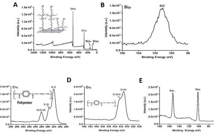
The topological integrity of the PETE membrane surface was assessed after treatment using Scanning Electron Microscopy (SEM) images (S4800, Hitachi High Technologies, USA). We investigate the binding of (i) Hydroxylated PMMA (OH-PMMA) to GLYMO-PETE membrane, and for comparison we also evaluate the binding of (ii) Hydroxylated PMMA (OH-PMMA) to APTES-PETE membrane, (iii ) APTES -PMMA for GLYMO-PETE membrane, and (iv) Hydroxylated PDMS (OH-PDMS) for GLYMO-PETE membrane. The microfluidic device was inverted and kept inside an incubator for 2 h to allow cell attachment on the upper PETE membrane layer.
Optical sectioning along the z-axis was performed to recreate the cell monolayer grown on the PETE membrane and obtain their spatial distribution in 3D. The integrity and stability of the bond between the PMMA and PETE membrane were evaluated by a uniform transmembrane pressure (UTP) shear test (4000 Plus Bondtester, Nordson Dage, OH, USA) (shear height: 20 μm, test speed: 500 μm s−1 , maximum cartridge weight: 200 kg). The bonded microfluidic chip was tightly placed in the sample holder, and the weight of the cartridge was increased over time until the top PMMA layer slipped off the PETE membrane, while the bottom PMMA layer remained attached to the porous membrane (Figure 3).
For comparison, we also evaluated other bonding strategies as shown in Table 1, where (i) hydroxylated PMMA (OH-PMMA) was bonded to APTES-PETE membrane and (iii) APTES-PMMA was bonded to GLYMO-PETE membrane. The maximum internal pressure was recorded before the fluid burst outside the channel using a pressure sensor (Harvard Apparatus, USA). Prepared drug solution then flowed through the lower channel of the microfluidic device at a flow rate of 25 μL/hour for 48 hours.

Result and discussion
- Bonding strategy and experimental validation
- Bonding strength evaluation
It is noticeable that there is a drastic increase in the proportion of C-H, C=O, C-O bonds in i) GLYMO-treated membranes compared to ii) APTES-treated PETE membranes (Figure 6). This higher reactivity is probably due to the higher bioreactivity of the hydroxyl group (-OH) of the PMMA substrates to the epoxy group in GLYMO than to the reaction with the amine group (–NH2) from APTES coated on the PETE membrane. However, contrary to our prediction, the bond strength between GLYMO-PETE and APTES-PMMA was not as high as that between GLYMO-PETE and OH-PMMA because the density of the amine groups formed on the PMMA substrate was much lower than the hydroxyl groups on the substrates Air and plasma treated PMMA.
We tested different concentrations of GLYMO and APTES to functionalize the surface in a range of 1 ~ 5%, and treating the PETE surface with 5% GLYMO resulted in the strongest bond with the PMMA substrates (data not shown). No leakage was found in the device even when we continuously supplied the solution for four weeks, and the success rate of the device fabrication was higher than 99%. While the PMMA device showed a clear and flat PETE membrane surface, the membranes integrated into the PDMS device were found to be wrinkled and warped, which is most likely due to the difference in the thermal expansion coefficient between the PETE membrane and the PDMS substrates (Fig. 7 A,B) .
7 C (left), cancer cells (A549) were well seeded inside the PMMA chip and easily recognized under a microscope, whereas the whole cell images in the PDMS chip cannot be captured in a specific focal plane due to the irregularly deformed membrane structures. Therefore, we predicted that there would be a similar result in the cytotoxicity test with drugs. We observed the cytotoxicity response of human lung adenocarcinoma cells to an anticancer drug (vincristine) after 48 h of treatment in the PMMA and PDMS devices.
The cytotoxicity of the cells cultured in the PMMA and PDMS devices showed a significant difference (P<0.05) when treated with 300 nM vincristine as shown in Fig. This can be explained as a significant amount of vincristine has been absorbed into PDMS due to the inherent hydrophobic molecular properties (LogP = 2.82), which in turn resulted in a reduction of the drug concentration below 300 nM in the culture medium and thus increased the cell viability of the cells processed in the PDMS device. Interestingly, when the cells were treated with a relatively higher concentration (1 µM), the difference in cytotoxicity between the PMMA and PDMS devices became negligible (Fig. 9).
The critical concentration for cells cultured on the PDMS device to be affected by the drug was not calculated as it depends on the chip design and surface area. In addition, we also tested the cytotoxicity of vincristine on PDMS devices, which were made from PDMS prepared with different ratios of PDMS precursors and a curing reagent, however, these were not evident at a rate of reduction of drug concentrations ( data not shown ). Given the results we obtained above, the material property of Microfluidic cytotoxicity devices, including thermal expansion coefficient and drug absorption, would be a significant concern when we need to detect subtle changes in drug toxicity at relatively low concentrations in the device.

Conclusion
Acknowledgment
I know I can be quite the handful at times, but deep down I am forever grateful and proud to call you my family. Thank you for stopping self-sabotage and instead opening yourself up to opportunities for growth every day. With so much uncertainty coming in the future, I owe it to my future self to work harder, dig deeper, constantly edit my own identity, and make my past self proud of what we have become.