저작자표시-비영리-변경금지 2.0 대한민국 이용자는 아래의 조건을 따르는 경우에 한하여 자유롭게
l 이 저작물을 복제, 배포, 전송, 전시, 공연 및 방송할 수 있습니다. 다음과 같은 조건을 따라야 합니다:
l 귀하는, 이 저작물의 재이용이나 배포의 경우, 이 저작물에 적용된 이용허락조건 을 명확하게 나타내어야 합니다.
l 저작권자로부터 별도의 허가를 받으면 이러한 조건들은 적용되지 않습니다.
저작권법에 따른 이용자의 권리는 위의 내용에 의하여 영향을 받지 않습니다. 이것은 이용허락규약(Legal Code)을 이해하기 쉽게 요약한 것입니다.
Disclaimer
저작자표시. 귀하는 원저작자를 표시하여야 합니다.
비영리. 귀하는 이 저작물을 영리 목적으로 이용할 수 없습니다.
변경금지. 귀하는 이 저작물을 개작, 변형 또는 가공할 수 없습니다.
Master’s Thesis
Reflected Object Removal in 360 Panormaic Images
Philjoon Jung
Department of Electrical Engineering
Graduate School of UNIST
[UCI]I804:31001-200000284949 [UCI]I804:31001-200000284949
Reflected Object Removal in 360 Panormaic Images
Philjoon Jung
Department of Electrical Engineering
Graduate School of UNIST
Abstract
When the reflected scene is captured in the 360◦ panoramic image, the actual scene of the reflection also taken together in the image. Based on this observation, we propose an algorithm that distinguishes the reflection and transmission layer in the glass image using the actual scene of reflection and removes the reflected objects from the panoramic image. We first separate the glass and background image by the user-assist manner and then extract feature points to warp the background image. However, it is challenging to match glass and background keypoints since the two images have different characteristics such as color and transparency. Therefore, we extract initial pairs of matched points using on the edge pixels and use the Dense-SIFT descriptor to match the correspondence points. We then transform the background image through APAP to generate a reference image, which we use to discriminate the reflection and transmission edge in the glass image. Then we determine the reflection and transmission edges based on the gradient angle and magnitude. Finally, based on the two separated edges, we solve the layer separation problem by minimizing the gradients of transmission image based on the gradient sparsity prior.
Contents
1 Introduction 1
2 Related Work 3
I Single Image Reflection Removal Algorithm . . . 3
II Reflection Removal Methods for Glass Images captured by Moving Camera . . . 5
3 Proposed Algorithm 6 I Overview . . . 6
II Image division with glass coordinates . . . 6
III Image Alignment . . . 7
3.1 Correspondence Matching . . . 7
3.2 Image Transformation . . . 10
IV Edge Separation . . . 11
V Layer Reconstruction . . . 13
4 Experimental Results 15
5 Conclusions 30
List of Figures
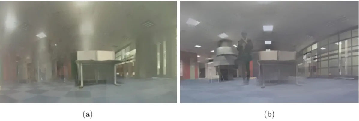
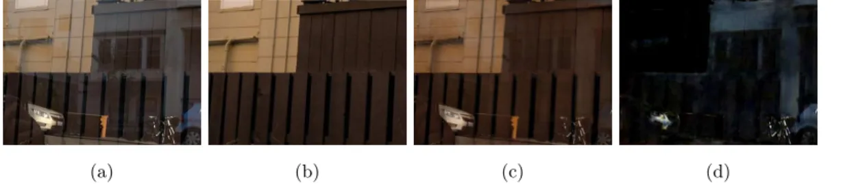
1 A failure case with strong reflection intensity (a) Glass imageG, (b) Groundtruth,
(c) Transmission image T and (d) Reflection imageR. . . 4
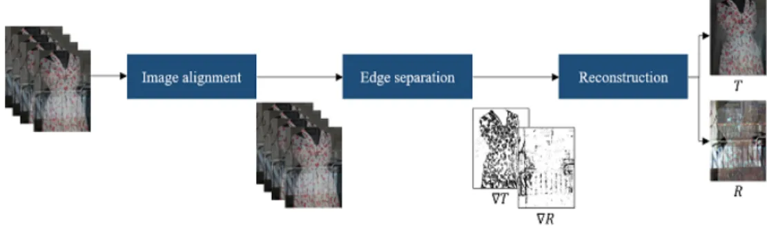
2 Overall algorithm of reflection removal using multiple images. . . 5
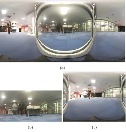
3 Glass and Background images (a) Input image I, (b) Glass image G, and (c) Background imageB. . . 7
4 Correspondence matching pairs of (a) SIFT, (b) SURF, (c) MSER and (d) FAST. 8 5 Co-saliency maps [1] of (a) Glass, and (b) Background. . . 8
6 Binary edge maps of Glass and Background (a) Glass Edge EG, and (b) Back- ground EdgeEB. . . 9
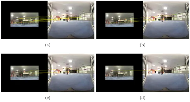
7 Matching Pairs (a) Initial correspondence Minit, and (b) Inlier correspondence MR. . . 10
8 Results of Transformation (a) Glass image G, and (b) Reference image B˜ . . . . 11
9 The gradient angle of reflection and transmission object. Blue circles represent reflected object which appear on the both images and red circles represent trans- mission object which only appear inG. . . 12
10 Results of edge separation (a) R, and (b)T . . . 13
11 Results of Transformation (a) TransmissionT, and (b) Reflection R . . . 13
12 Reconstructed360◦ panoramic image . . . 14
13 Experimental images and resluts (a) Original, (b) Glass, (c) Reference image, (d) the proposed algorithm, (e) Transmission layer, and (f) Reflection layer. . . 16 14 Experimental images and resluts (a) Original, (b) Glass, (c) Reference image, (d)
the proposed algorithm, (e) Transmission layer, and (f) Reflection layer. . . 17 15 Experimental images and resluts (a) Original, (b) Glass, (c) Reference image, (d)
the proposed algorithm, (e) Transmission layer, and (f) Reflection layer. . . 18 16 Experimental images and resluts (a) Original, (b) Glass, (c) Reference image, (d)
the proposed algorithm, (e) Transmission layer, and (f) Reflection layer. . . 19 17 Experimental images and resluts (a) Original, (b) Glass, (c) Reference image, (d)
the proposed algorithm, (e) Transmission layer, and (f) Reflection layer. . . 20 18 Experimental images and resluts (a) Original, (b) Glass, (c) Reference image, (d)
the proposed algorithm, (e) Transmission layer, and (f) Reflection layer. . . 21 19 Experimental images and resluts (a) Original, (b) Glass, (c) Reference image, (d)
the proposed algorithm, (e) Transmission layer, and (f) Reflection layer. . . 22 20 Experiment results of comparison. (a) Glass image, (b) Reference image, (c - d)
T and R of [2], (e - f)T and R of [3], (g - h) T and R of [4] and (i - j) T and R of Proposed method. . . 23 21 Experiment results of comparison. (a) Glass image, (b) Reference image, (c - d)
T and R of [2], (e - f)T and R of [3], (g - h) T and R of [4] and (i - j) T and R of Proposed method. . . 24 22 Experiment results of comparison. (a) Glass image, (b) Reference image, (c - d)
T and R of [2], (e - f)T and R of [3], (g - h) T and R of [4] and (i - j) T and R of Proposed method. . . 25 23 Experiment results of comparison. (a) Glass image, (b) Reference image, (c - d)
24 Experiment results of comparison. (a) Glass image, (b) Reference image, (c - d) T and R of [2], (e - f)T and R of [3], (g - h) T and R of [4] and (i - j) T and R of Proposed method. . . 27 25 Experiment results of comparison. (a) Glass image, (b) Reference image, (c - d)
T and R of [2], (e - f)T and R of [3], (g - h) T and R of [4] and (i - j) T and R of Proposed method. . . 28 26 Experiment results of comparison. (a) Glass image, (b) Reference image, (c - d)
T and R of [2], (e - f)T and R of [3], (g - h) T and R of [4] and (i - j) T and R of Proposed method. . . 29
List of Tables
Chapter 1
Introduction
With the development of electronic devices, communication system and digital image processing, we live in a world where anyone can easily take pictures or videos and watch them regardless of time and place. This trend is not only applied for traditional 2D images, but also for 360◦ panoramic images represented for AR and VR. However compared to the increased demand, there is still a lack of research to assist users in taking desired360◦ panoramic image. Although the reflections on the glass surface interfere with taking the target scene, reflection removal studies on the panoramic image have not yet been conducted.
Reflection removal is a method to seperate a glass image into a reflection and a transmission layer automatically. Attempts have been conducted to remove reflection layers for 2D images, and are classified into single image reflection removal and multi-image reflection removal.
Single image reflection removal is a study that removes a reflection image by using different characteristics of the transmission and the reflection image. In most cases, since there is a lack of information to distinguish the reflection and the transmission layer, they solved the problem by employing a smooth prior that the reflected image is smoother than the transmission image.
In many cases, however, there are a lot of occations that do not fit the above prior, so there is a limit to using single image reflection removal technique to separate transmission and reflection scene in 360◦ panoramic images.
Another methods, multi-image reflection removal techniques, is to separate the transmission and reflection layers with two or more(typically four or five) images. they have removed reflection artifacts much more accurately than single layer separation as they can extract information about reflections and transmissions. However, due to the dataset is composed of two or more similar glass images, these methods have difficulties to directly apply for the single panoramic image.
In this thesis, we first propose an algorithm that removes reflections from 360◦ panoramic
images. In the case of a panoramic image, there is a characteristic that an image reflected on glass and an actual image exist in one image. With this porperty, we get an input panoramic image and glass region coordinates from a user and automatically remove the reflection image in the area. First, we divide the input image into a glass image and a background image, and take edge pixel coordinates as keypoint candidates. Then match the corredpondence between glass and background image and use RANSAC to extract inlier correspondence matching points.
we generate referecne image by transforming the background image with moving DLT method.
We divide the transmission and reflection edges based on the gradinet magnitude and angular similarity. Finally, we reconstruct the transmission and reflection image by minimizing Levin’s loss fucntion and Poisson solver function is used for removing color distortion. The experimental results show that our method can be effectively remove the reflection artifacts in the panoramic image.
Chapter 2
Related Work
I Single Image Reflection Removal Algorithm
Reflection removal is a process to separate transmission and reflection layer from a glass image, where the input image I is a linear combination of transmission image T and reflection image R as illustrated in equation 2.1:
I =T +R (2.1)
Since reflection removal using a single glass image is an ill-posed problem, early studies [5], [6] as- signed the coordinates of the reflected object directly to remove them. Levinet al.[5] separated transmission layer and reflection layer with eqn. 2.1 by minimizing the number of edges and corners. However, it only worked well for a simple glass scene. To alleviate this problem, Levin and Weiss [6] decomposed the input into the transmission and reflection image by optimization manner with the gradient sparsity prior. Based on the gradient sparsity prior, Levin proved that the edges of two natural images rarely overlap when a new image is created by adding two natural images. Levin reconstructed the transmission image and reflection image with the di- vided gradient maps based on the optimization manner. However, this method has a limitation in that the user needs to assign the region where the reflected artifacts appear. Subsequent studies used various assumptions to remove reflected objects without user assistance. Yu Li et al.[2] proposed SRS, which is a method of reflection removal in a single image without any help from the user. With the smoothness prior that the gradient histogram of the reflection layer is smoother than the transmission layer, Yu Li separated the reflection layer and transmission layer based on the optimization manner. However, there are many cases where the gradient histogram of the reflected image is not smoother than the transmission image, which shows a limitation in practice.
Since the advent of Alexnet [7], a convolutional neural network(CNN) has emerged as an im- portant method of computer vision research. The single image reflection removal networks [3,4,8]
have also been proposed based on this research trend. In this field, researchers have used se- mantic segmentation networks such as FCN [9] and U-Net [10] as baselines. The first research to apply CNN to reflection removal is CEILNet [8] based on FCN. Fanet al.[8] proposed CEIL- Net, which detects the transmission edge map and reconstructs the transmission image. They first trained the edge prediction network(E-Net) that detects the transmission edge map when the inputs are the glass image and the edge of the glass and trained the image reconstruction network(I-Net) that receives the detected edge and glass image for transmission scene reconstruc- tion. However, since the training data consisted of the glass images with the smoothness prior, it is difficult to remove the reflection effectively when the input is not fit in the prior. Zhanget al.[3] proposed RSPL, which used feature loss from a visual perception network, adversarial loss to refine the output transmission layer and exclusion loss to separate transmission and reflection edges. They consisted of glass-transmission pair dataset with 5,000 synthetic images and 110 real images. However, they could not remove the sharp reflection since the amount of data is insufficient to train the network deals with various reflection intensities illustrated in Fig. 1. Jie et al. [4] proposed a deep neural network with a cascaded structure, which is referred to as the BDN. Unlike the existing methods [3, 8], which used only glass and transmission images, they constructed a dataset including input, transmission, and reflection images. The transmission image is extracted through the U-Net, and they put the result into the bidirectional unit to correct the reflection and transmission layers. We compare the results of proposed algorithm with the results of SRS [2], RSPL [3] and BDN [4] in Chapter 4.
(a) (b) (c) (d)
Figure 1: A failure case with strong reflection intensity (a) Glass imageG, (b) Groundtruth, (c) Transmission imageT and (d) Reflection imageR.
II Reflection Removal Methods for Glass Images captured by Moving Camera
Levin and Weiss separated transmission and reflection layers effectively. However, the user assistant manner of allocating the transmission edge and the reflection edge was a drawback of the algorithm. Several attempts have been made to compensate for this drawback using glass images with different camera angles and positions. Li and Brown [11] proposed automatic method for removing reflection artifacts using SIFT-flow [12]. The dataset consists of three to five images taken from slightly different viewpoints. Such characteristics of the dataset lead to the assumption that the edges of the transmission image are evenly present in all images, while the edges of the reflection image are sparse and varying. As a result, Yu Li matched keypoint features through SIFT-flow, one of the optical flow methods, and warped the remaining images to match the reference image. After image aligning, the transmission and reflection edges were classified with respect to the appearance frequency, which is measured by the gradient magnitudes at a given pixel location. After edge separation, Yu Li minimize the cost function [6] by iterative reweighted least square [13] method.
Figure 2: Overall algorithm of reflection removal using multiple images.
Han and Sim [14] proposed a multi-view reflection removal algorithm using co-saliency de- tection and low-rank matrix completion. They observed that existing methods hadn’t provided robust removal performance for various reflective environments. Therefore they used co-saliency detection [15] to perform correspondence matching by assigning edge pixels that have high co- saliency values as the keypoint candidates. Then, they used the magnitude of the gradient to separate the reflection and transmission gradient maps and fulfilled the transmission map with low-rank matrix completion. To obtain an optimal solution, they apply the expectation- maximization(EM) algorithm in an iterative manner.
Chapter 3
Proposed Algorithm
I Overview
Actual objects reflected on the glass always exist in360◦ panoramic image. With this property, we propose the reflected objects removal algorithm using the single360◦ panoramic image and glass region coordinates in the user-assisted manner. We first divide the input image into a glass image and a background image based on the glass coordinates and detect edge pixels in both images. Set the edge pixels as the keypoints of the image and match the correspondence between glass and background image with Dense-SIFT [16] descriptor. Use RANSAC [17] to extract inlier correspondence matching points and transform the background image with moving DLT method to generate a reference image. We divide the transmission and reflection edges based on the gradient magnitude and angular similarity. Edges with similar angles to the reference image are identified by reflection edges and vice versa by transmission edges. Finally, we reconstruct the transmission and reflection image by minimizing Levin’s loss function, and the Poisson solver function is used for removing color distortion. The experimental results show that our method can effectively remove the reflection artifacts in the panoramic image.
II Image division with glass coordinates
The360◦panoramic image with glass can be divided into a glass area and other areas. Therefore, with the glass coordinates R assigned by the user, we divide the image into a glass region G and the remaining area where the actual objects reflected on the glass are located. We call that
always y-axis symmetry. Therefore we flip B on the y-axis.
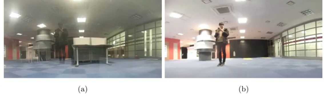
(a)
(b) (c)
Figure 3: Glass and Background images (a) Input image I, (b) Glass imageG, and (c) Back- ground imageB.
III Image Alignment
3.1 Correspondence Matching
[11], [14] tried to remove reflection in the set of multiple glass images with camera positions.
Since the image frames were captured along the camera movement, feature extraction could be defined as an optical flow problem [18]. They especially used SIFT-flow [12], which extracts the features most robustly, for the correspondence matching. However, in the 360◦ panoramic image, it does not fit the above problem as there is no camera movement, and the two images have different image characteristics. Therefore, we need a method of feature matching between the glass and natural images to find the pixel pairs with the most similar description.
There are lots of keypoints-based algorithms, and one of the most famous methods is SIFT [19]. Due to its invariance in scale and orientation, SIFT is still used today. However since reflected scene on the glass has small gradient magnitude, most keypoints extraction methods, including SIFT, SURF [20], BRISK [21], KAZE [22], FAST [23], and MinEigen [24] method, do
not extract a sufficient amount of exact keypoints matching pairs.
(a) (b)
(c) (d)
Figure 4: Correspondence matching pairs of (a) SIFT, (b) SURF, (c) MSER and (d) FAST.
Therefore, we need to find enough and exact keypoints matching pairs. Han [14] suggested using the co-saliency map to detect common objects and extract keypoints candidates around the edges of these objects. However, co-saliency detection [1], [25], which depends on RGB or Lab color space, cannot provide proper candidates because the object features in Gand B are different.
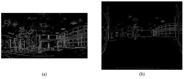
Figure 5: Co-saliency maps [1] of (a) Glass, and (b) Background.
To find the proper keypoints, we analyze the common features of both glass and background
Also, since keypoints are usually detected near edges and corners, we define edge pixels of G and B as keypoint candidate sets FG, FB respectively.
FG={p|EG(p) = 1}, FB={q|EB(q) = 1} (3.1) where p denotes the pixel location of glass edge map EG, and q denotes the pixel location of background edge map EB.
Figure 6: Binary edge maps of Glass and Background (a) Glass EdgeEG, and (b) Background Edge EB.
The SIFT descriptor is a 128-dimensional vector representing very strong features that are invariant to illumination, translation, and scale for each keypoint. We can see in Fig. 4 (a) that though the number of matched pairs is insufficient, the matching pairs between G and B are highly accurate. Therefore we use Dense-SIFT [16], which extracts the SIFT descriptors for specified pixels, and then tries to find correspondence matching between the two images. So we extract the descriptor DG from the FG and descriptor DB from the FB and calculate the Euclidean distance of these two descriptorsL2(DG, DB).
Initial correspondence matching Minit takes only pairs with satisfy:
Minit={pi↔qj |L2(DG(pi), DB(qj))∗β≤L1(DG(pi))} (3.2) where DG(pi) is the descriptor of i-th pixel pi and DB(qj) is the descriptor of j-th pixel qj. L2(DG(pi), DB(qj)) is the Euclidean distance of the two descriptors, β is the threshold and L1(DG(pi))is the Manhattan distance of descriptor DG(pi).
Then, we adopt RANSAC [17] for eliminating false matching pairs. We set inlier matching pairs as MR
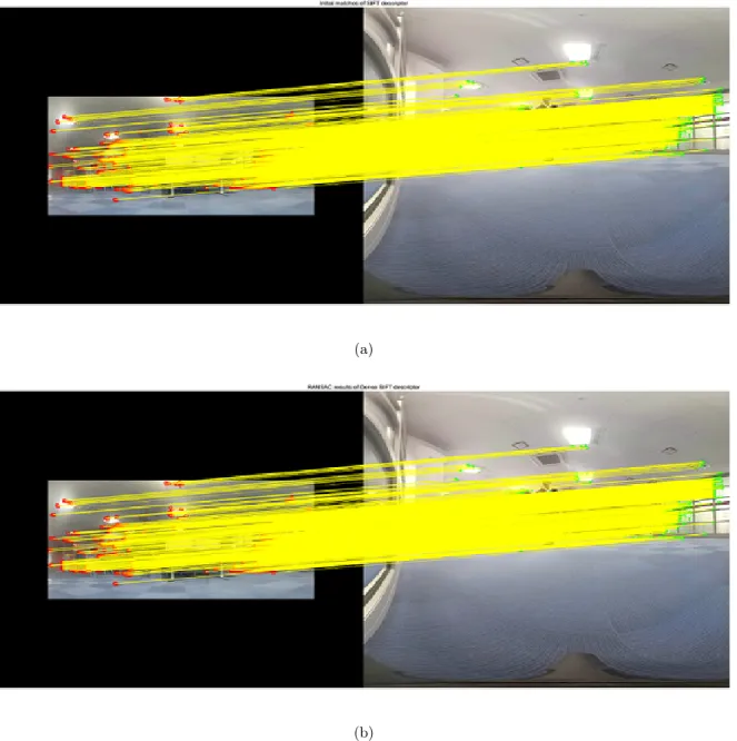
(a)
(b)
Figure 7: Matching Pairs (a) Initial correspondenceMinit, and (b) Inlier correspondenceMR.
3.2 Image Transformation
Traditionally, the most commonly used image alignment method is the homography transform, which transforms the image intoR2 plane. It works well in situations where the scene is planar or taken only with the camera rotates. However, since the 360◦ panoramic image is a spherical image, the conditions mentioned above are not satisfied in reality, and artifacts such as ghosting effects occur frequently.
significantly and increased the image stitching accuracy compared to conventional homography warping. Therefore, we apply APAP to transform the background image B to generate the reference imageB, where the edge pixels are almost similar to˜ G.
(a) (b)
Figure 8: Results of Transformation (a) Glass image G, and (b) Reference image B˜
IV Edge Separation
Based on the gradient sparsity prior to natural image [6], it is negligible that the edges in the glass image belong to both the transmission and the reflection scene. Therefore we will divide the glass edges EG into the transmissionET, and the reflection edges ER.
Previous reflection removal algorithms with single glass image [2], [8], [27] have removed reflected artifacts with the smoothness prior that the reflection images are smoother or blurrier than the transmission image. It works well in situations where the reflection scene has no apparent features such as edge or corner points. However, in most cases, the reflection image is not smooth and has distinct features. Therefore, the prior is inconsistent, and the conventional single-layer separation methods do not work well.
Since we use two images(the glass image and the reference image), it can be considered as the multiple images. But unlike the existing methods [2], [28], [14], this problem has different set of data. Existed multiple glass datasets consisted of images with slightly different camera positions, and it was related to the fact that reflection edges are distributed without consistency.
Since the features of transmission objects are similar, existed methods estimated consistency of transmission edges using gradient magnitudes. However, the images used in this problem have different characteristics. Therefore, it is unnatural to separate edges with the above manner because the gradient difference is large.
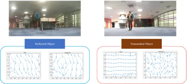
We separate the edges differently from the conventional method. Though the gradient mag- nitudes of the two images are different, the gradient angle of the reflection scene in the glass
image and the reference image are similar. Therefore we distinguish reflection and transmission edges by the magnitude and angle of the gradient.
Figure 9: The gradient angle of reflection and transmission object. Blue circles represent reflected object which appear on the both images and red circles represent transmission object which only appear in G.
We first select pixels with the gradient magnitude exceeding the threshold from G and B,˜ respectively. Then do hadamard products to take pixels on both the glass and reference images as the reflection edge candidatesE.
EG=
1, ||∇G||2> T hg 0, otherwise
, EB˜ =
1, ||∇B˜||2> T hb 0, otherwise
(3.3)
E =EG◦EB˜ (3.4)
where◦ is hadamard product.
The angular similarity α(x) is the angle between reflection and transmission gradients. We calculated the reflection and transmission probabilities for the pixels on E as eqn.3.6, 3.7
α(x) = arccos h∇G(x),∇B˜(x)i
||∇G(x)||2||∇B(x)||˜ 2
!
(3.5) whereh,iis the inner product operation.
PrR(x) = 1
1 +e−α(x)/σ (3.6)
Finally, we designate the reflection edges R and transmission edges T. Empiricaly, we set the reflection edges that PrR >0.9 and the transmission edges are the glass edges except the reflection edges. Separated edges are illustrated in Fig. 10.
(a) (b)
Figure 10: Results of edge separation (a)R, and (b) T
V Layer Reconstruction
After the separation of gradient edges, we follow the [6] to reconstruct the transmission and reflection image from the gradients. Levin and Weiss proved that the gradient distribution of natural images could be modeled by the linear sum of two Laplacian distribution and be a key to reconstruct the images by minimizing the cost function defined as eqn. ??. Here, we use two orientations and two degrees of Sobel filters. The first term enforces the sparsity while the last two terms require the recovered image gradients to follow our separation.
(a) (b)
Figure 11: Results of Transformation (a) Transmission T, and (b) Reflection R
Since Levin’s method occurs color distortion, we use Poisson solver function [29] with theG as a boundary map on the gradientT to alleviate the distortion.
Figure 12: Reconstructed 360◦ panoramic image
Chapter 4
Experimental Results
Since there is no existing research to remove reflections from360◦panoramic images, there are no 360◦panorama datasets with reflected objects, so we have taken the images with GoPro Fusion, a 360◦ panoramic camera. The camera consists of two fisheye lenses and generates a spherical image by stitching the two images taken from each lens. We experimented by transforming it into a 2D image. Since the resolution of the panoramic image is5760×2880, which means the computation is too complex, we use0.3rescaled images, 1728×864.
We compare with a single reflection removal algorithm, SRS [2], and two deep learning methods, RSPL [3] and BDN [4]. The methods based on multiple images did not work since correspondence matching points could not be extracted properly, resulting in severe homography transform error.
BDN showed strong points for removing the smooth objects well, yet weak performance for the strongly reflected objects. The rest of the methods rarely erase the reflected objects from the image. This suggests that the proposed algorithm is better than the existing algorithm and deep learning network for the reflection removal of the panoramic image, especially for the strong reflection.
(a)
(b) (c)
(d)
(e) (f)
(a)
(b) (c)
(d)
(e) (f)
Figure 14: Experimental images and resluts (a) Original, (b) Glass, (c) Reference image, (d) the proposed algorithm, (e) Transmission layer, and (f) Reflection layer.
(a)
(b) (c)
(d)
(e) (f)
(a)
(b) (c)
(d)
(e) (f)
Figure 16: Experimental images and resluts (a) Original, (b) Glass, (c) Reference image, (d) the proposed algorithm, (e) Transmission layer, and (f) Reflection layer.
(a)
(b) (c)
(d)
(e) (f)
(a)
(b) (c)
(d)
(e) (f)
Figure 18: Experimental images and resluts (a) Original, (b) Glass, (c) Reference image, (d) the proposed algorithm, (e) Transmission layer, and (f) Reflection layer.
(a)
(b) (c)
(d)
(e) (f)
(a) (b)
(c) (d)
(e) (f)
(g) (h)
(i) (j)
Figure 20: Experiment results of comparison. (a) Glass image, (b) Reference image, (c - d) T and R of [2], (e - f) T and R of [3], (g - h) T and R of [4] and (i - j) T and R of Proposed method.
(a) (b)
(c) (d)
(e) (f)
(g) (h)
(i) (j)
Figure 21: Experiment results of comparison. (a) Glass image, (b) Reference image, (c - d) T and R of [2], (e - f) T and R of [3], (g - h) T and R of [4] and (i - j) T and R of Proposed
(a) (b)
(c) (d)
(e) (f)
(g) (h)
(i) (j)
Figure 22: Experiment results of comparison. (a) Glass image, (b) Reference image, (c - d) T and R of [2], (e - f) T and R of [3], (g - h) T and R of [4] and (i - j) T and R of Proposed method.
(a) (b)
(c) (d)
(e) (f)
(g) (h)
(i) (j)
Figure 23: Experiment results of comparison. (a) Glass image, (b) Reference image, (c - d) T and R of [2], (e - f) T and R of [3], (g - h) T and R of [4] and (i - j) T and R of Proposed
(a) (b)
(c) (d)
(e) (f)
(g) (h)
(i) (j)
Figure 24: Experiment results of comparison. (a) Glass image, (b) Reference image, (c - d) T and R of [2], (e - f) T and R of [3], (g - h) T and R of [4] and (i - j) T and R of Proposed method.
(a) (b)
(c) (d)
(e) (f)
(g) (h)
(i) (j)
Figure 25: Experiment results of comparison. (a) Glass image, (b) Reference image, (c - d) T and R of [2], (e - f) T and R of [3], (g - h) T and R of [4] and (i - j) T and R of Proposed
(a) (b)
(c) (d)
(e) (f)
(g) (h)
(i) (j)
Figure 26: Experiment results of comparison. (a) Glass image, (b) Reference image, (c - d) T and R of [2], (e - f) T and R of [3], (g - h) T and R of [4] and (i - j) T and R of Proposed method.
Chapter 5
Conclusions
We proposed a reflected object removal algorithm for 360irc panoramic images. The reflection and the transmission image were distinguished using the characteristics of the panoramic image that the actual image reflected on the glass exists in the image. We reconstruct the transmission scene using the layer separation method proposed with Levin. While the existing deep learning techniques are weak for strong reflections, our algorithms do a good performance of removing reflected artifacts. However, it is still weak in removing homogeneous objects like the sky. Future work will be carried out to remove the homogenious areas.
References
[1] H. Fu, X. Cao, and Z. Tu, “Cluster-based co-saliency detection,” IEEE Trans. Image Pro- cess., vol. 22, no. 10, pp. 3766–3778, 2013.
[2] Y. Li and M. S. Brown, “Single image layer separation using relative smoothness,” inProc.
IEEE CVPR, 2014, pp. 2752–2759.
[3] X. Zhang, R. Ng, and Q. Chen, “Single image reflection separation with perceptual losses,”
inProc. IEEE CVPR, 2018, pp. 4786–4794.
[4] J. Yang, D. Gong, L. Liu, and Q. Shi, “Seeing deeply and bidirectionally: a deep learning approach for single image reflection removal,” in Proc. ECCV, 2018, pp. 654–669.
[5] A. Levin, A. Zomet, and Y. Weiss, “Separating reflections from a single image using local features,” in Proc. IEEE CVPR, vol. 1, 2004, pp. I–306–I–313.
[6] A. Levin and Y. Weiss, “User assisted separation of reflections from a single image using a sparsity prior,” IEEE Trans. Pattern Anal. Mach. Intell., vol. 29, no. 9, pp. 1647–1654, 2007.
[7] A. Krizhevsky, I. Sutskever, and G. E. Hinton, “Imagenet classification with deep convolu- tional neural networks,” in Proc. NeurIPS, 2012, pp. 1097–1105.
[8] Q. Fan, J. Yang, G. Hua, B. Chen, and D. Wipf, “A generic deep architecture for single image reflection removal and image smoothing,” inProc. IEEE ICCV, 2017, pp. 3238–3247.
[9] J. Long, E. Shelhamer, and T. Darrell, “Fully convolutional networks for semantic segmen- tation,” in Proc. IEEE CVPR, 2015, pp. 3431–3440.
[10] O. Ronneberger, P. Fischer, and T. Brox, “U-net: Convolutional networks for biomedical image segmentation,” in Proc. MICCAI, 2015, pp. 234–241.
[11] Y. Li and M. S. Brown, “Exploiting reflection change for automatic reflection removal,” in Proc. IEEE ICCV, 2013, pp. 2432–2439.
[12] C. Liu, J. Yuen, and A. Torralba, “Sift flow: Dense correspondence across scenes and its applications,” IEEE Trans. Pattern Anal. Mach. Intell., vol. 33, no. 5, pp. 978–994, 2010.
[13] P. Meer, “Robust techniques for computer vision,” Emerging topics in computer vision, pp.
107–190, 2004.
[14] B. Han and J. Sim, “Glass reflection removal using co-saliency-based image alignment and low-rank matrix completion in gradient domain,” IEEE Trans. Image Process., vol. 27, no. 10, pp. 4873–4888, Oct 2018.
[15] C. Lee, W.-D. Jang, J.-Y. Sim, and C.-S. Kim, “Multiple random walkers and their appli- cation to image cosegmentation,” in Proc. IEEE CVPR, 2015, pp. 3837–3845.
[16] A. Bosch, A. Zisserman, and X. Munoz, “Image classification using random forests and ferns,” in Proc. IEEE ICCV, 2007, pp. 1–8.
[17] M. A. Fischler and R. C. Bolles, “Random sample consensus: a paradigm for model fitting with applications to image analysis and automated cartography,” Comm. ACM, vol. 24, no. 6, pp. 381–395, 1981.
[18] A. Bruhn, J. Weickert, and C. Schnörr, “Lucas/kanade meets horn/schunck: Combining local and global optic flow methods,” Int’l J. Comput. Vis., vol. 61, no. 3, pp. 211–231, 2005.
[19] D. G. Lowe, “Distinctive image features from scale-invariant keypoints,” Int’l J. Comput.
Vis., vol. 60, no. 2, pp. 91–110, 2004.
[20] H. Bay, T. Tuytelaars, and L. Van Gool, “Surf: Speeded up robust features,” inProc. ECCV, 2006, pp. 404–417.
[21] S. Leutenegger, M. Chli, and R. Siegwart, “Brisk: Binary robust invariant scalable key- points,” in Proc. IEEE ICCV, 2011, pp. 2548–2555.
[22] P. F. Alcantarilla, A. Bartoli, and A. J. Davison, “Kaze features,” in Proc. ECCV, 2012, pp. 214–227.
[23] E. Rosten and T. Drummond, “Fusing points and lines for high performance tracking.” in
[25] X. Cao, Z. Tao, B. Zhang, H. Fu, and W. Feng, “Self-adaptively weighted co-saliency de- tection via rank constraint,” IEEE Trans. Image Process., vol. 23, no. 9, pp. 4175–4186, 2014.
[26] J. Zaragoza, T.-J. Chin, M. S. Brown, and D. Suter, “As-projective-as-possible image stitch- ing with moving dlt,” in Proc. IEEE CVPR, 2013, pp. 2339–2346.
[27] R. Wan, B. Shi, T. A. Hwee, and A. C. Kot, “Depth of field guided reflection removal,” in Proc. IEEE ICIP, 2016, pp. 21–25.
[28] X. Guo, X. Cao, and Y. Ma, “Robust separation of reflection from multiple images,” in Proc. IEEE CVPR, 2014, pp. 2187–2194.
[29] T. Simchony, R. Chellappa, and M. Shao, “Direct analytical methods for solving poisson equations in computer vision problems,” IEEE Trans. Pattern Anal. Mach. Intell., vol. 12, no. 5, pp. 435–446, 1990.
![Figure 5: Co-saliency maps [1] of (a) Glass, and (b) Background.](https://thumb-ap.123doks.com/thumbv2/123dokinfo/10486829.0/20.892.227.728.718.968/figure-5-saliency-maps-1-glass-b-background.webp)