3 SEM images of (a) macroporous silica and (b) Si particles prepared by magnesiothermal reaction of the porous silica… 110 Figure 6. 7 Raman spectrum of carbon coated Si-Al-7-3 composite indicates characteristics of amorphous carbon layer (with D/G ratio of Figure 6. 8 Electrochemical performance of macroporous Si/Al2O3 composite electrodes with four different Al2O3 contents………116 Figure 6. 9 The dQ/dV plots of three composite electrodes during the first cycle ……… 116 Figure 6. 10 Electrochemical performance of carbon-coated non-porous Si electrodes obtained by magnesiothermal reaction.... 117 Figure 6. b) Enlarged image of Si-Al-7-3 (yellow box too see in Figure 6. 12a) with mesoporous structure.
Nano-Engineering and Nanotechnology
- Introduction: Progress of Nano-engineering (Nanotechnology) in Industry
- Various Approaches of Nano-engineering
- Bottom-Up Approach
- Top-Down Approach
- General Approaches for Industry
- Recent Progress of Nano-engineering in Applications
- Advanced Semiconductor Device
- Development of Li-Ion Batteries
- Various Applications
- References
When masks are used, the lithographic process produces a 2D replica of the pattern on the mask. The combination of shadow mask and scanning probe methods such as atomic force microscope (AFM) and scanning tunneling microscope (STM) provide improved manipulation of the pattern structures.

Main Components of Lithium-Ion Batteries
Introduction: Li-Ion Rechargeable Batteries for electric Energy Storage System (ESS)
- History of Li-Ion Batteries
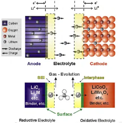
- Theory of Li-Ion Batteries
At first glance, the electrochemical process that powers the lithium-ion battery seems quite simple, apparently consisting of the reversible exchange of lithium ions between the two electrodes. Li and that the graphite anode works well beyond the stability of the electrolyte and the cathode is just at its limit.

Composition Materials in Li-Ion Batteries
- Cathode
- Anode
- Carbon-based Materials
- Alloy/de-alloy Materials
- Conversion Materials
- Separator
- Electrolyte
- Current Collector
We will discuss the latest technology of anode materials for LIBs, with special emphasis on recent nanotechnology results and outstanding results. The conclusion was that the carbon coating can reduce the decomposition of the electrolyte and can lead to the formation of a thin SEI on the electrode surface.

Next Generation Li-Ion Batteries
- New designed Li-Ion Batteries
- Flexible Li-Ion Batteries
The mechanical and electrochemical properties of flexible LIBs depend on how the battery components, i.e., electrodes, electrolytes, and separators, are combined into a single device. In particular, with repeated deformation of a flexible LIB, stable interfacial contact between electrode and electrolyte is of critical importance.

Liu, Q.; Mao, D.; Chang, C.; Huang, F., Phase transformation and morphology evolution during hydrothermal preparation of orthorhombic LiMnO 2 nanorods for lithium ion battery application. Ji, L.; Lin, Z.; Alcoutlabi, M.; Zhang, X., Recent developments in nanostructured anode materials for rechargeable lithium-ion batteries.
Patterning of Electrodes for Mechanically Robust and Bendable Lithium-ion
- Introduction
- Experimental
- Fabrication of micro patterned copper substrates
- Result and discussion
- A synthesis of CuO nano-flake electrodes
- Mechanical properties of Cu electrodes for bendable electrode
- Electrochemical properties of CuO electrodes
- Conclusion
- References
The CuO nanoflake structures grown on the Cu foils were further confirmed by transmission electron microscopy (TEM) (Figure 3.2e). The CuO nano-flakes were aggregated and SEI layers on the surface of the CuO were formed. Three-dimensional nanostructured CuO nanoflakes material was grown on the patterned Cu foils via a solution immersion process.

High-Power Li-Ion Batteries Using Multi-scale Lithographic Patterning of
Introduction
However, the above examples did not meet high electrical storage capacity (high energy density) and high capacity (high power density) due to limited loading amount of active materials. Herein, we demonstrate lithographically patterned electrodes consisting of micro- and nano-scale patterns, where the multi-scale patterns provide surface enhancement and strong adhesion between active materials and the current collector surface. When LiFePO4 cathode, Li4Ti5O12 and Si anode materials are applied to these electrodes using the lithographically formed current collectors, the excellent electrochemical performance of various active materials is achieved, including high power (LiFePO4: 96 mAhg-1 at 100° C, Li4Ti5O12: 140 mAhg-1 at 10C, Si: 825 mAhg-1 at 5C) and very stable cycling performance.
Experimental
- Fabrication of patterned current collectors
- LiFePO 4 synthesis
- Anode materials
- Characterization
- Electrochemical test
The LTO anode electrodes for the half-cell test were composed of Li4Ti5O12 powder, super-P carbon black, and polyvinylidene fluoride (PVdF) binder in a weight ratio of 8:1:1. The cathode electrodes for the half-cell test were composed of LiFePO4 powder, super-P carbon black, and polyvinylidene fluoride (PVdF) binder in a weight ratio of 8:1:1. The half-cells were tested with galvanostatic charge-discharge measurements between 4.3 and 2.0 V (versus Li/Li+) at various C rates (0.1C–500C).

Result and discussion
- Characterization of the patterned electrodes
- Study on effects of the patterned electrodes
- Positive effects of the patterning compared to other conditions
- Applying patterned electrode to anode materials
The same amount of co-LFP material (≈ 1.5 mg) was loaded into the patterned and non-patterned current collectors. The pattern current collectors (12 µm deep) containing in-pattern mass with low-load above-pattern mass (10 µm thick) were compared with the same current collectors containing in-pattern mass with high-load above-pattern mass (80 µm) thick) ( Figure 4.8). Similar to the results of the co-LFP cathode, initial capacity and coulombic efficiency do not differ much in the patterned and the non-patterned electrodes.

Conclusion
Guo, J.; Wang, C., A polymer scaffold bonding structure for high-capacity lithium-ion battery silicon anode. Yao, M.; Okuno, K.; Iwaki, T.; Kato, M.; Tanase, S.; Emura, K.; Sakai, T., LiFePO 4-based electrode using micro-porous current collector for high-power lithium-ion batteries. C.; Zhang, J.-G., An approach to make macroporous metal foils as current collectors for lithium-ion batteries.
Micro-assembled Si / Titanium Silicide Nanotube Anodes for High-Performance
- Introduction
- Experimental
- Synthesis of CNT@Si and Si, Si@Ti x Si y nanotube structure
- Characterization of materials
- Electrochemical test
- Result and discussion
- Morphologies of Si-based nanotube materials
- Characterization of Si-based nanotube with titanium
- Conclusion
- References
The electrochemical properties of the carbon-coated CNT@TiC/TixSiy@Si electrodes were comparable to those of carbon-coated CNT@SiC@Si electrodes. The XRD patterns of TixSiy@Si-NT after dissolution of MgO by-products show that crystalline Si (major component) and TixSiy (minor components) are detected (Figure 5. 7c). The first cycle voltage profile and (b) cycle performance of the carbon-coated CNT@TiC/TixSiy@Si electrodes were obtained in the range of 0.01–1.2 V.

Metallothermic reduction for macroporous Si: compromise between capacity and
Introduction
Metallothermic reduction for macroporous Si: Compromise between capacity and volume expansion for Li-Ion batteries. This is why there must be a compromise between a reversible capacitance and a volumetric expansion of the Si electrodes. This process enables us to control the specific capacitance and volume expansion of shape-retaining macroporous Si-based anodes.
Experimental
- Synthesis of micro-/nanoporous Si particles
- Characterization of porous Si particles
- Electrochemical properties of shape-preserving porous Si anodes
Result and discussion
- One-step reduction process of macroporous SiO 2 particles
- Two-step reduction process of macroporous SiO 2 particles
- Electrochemical properties of Si anodes synthesized via two-step reduction process.115
EDS mapping results of samples (seen in Figure 6. 1d) indicate that (e) oxygen (green), (f) Al (yellow), and (g) Si (magenta) are uniformly distributed in the Si/Al2O3 composite. SEM image of the FIB-sectioned sample shows that Si-Al-7-3 retains tubular cylinder structure of original diatomite (Figure 6. 5e). Moreover, the Si/Al2O3 composite electrode shows a significant reduction of open circuit voltage (OCV) in a fully lithiated state after 100 cycles (Figure 6. 8d).

Conclusion
He, Y.; Yu, X.; Wang, Y.; Li, H.; Huang, X., Alumina-coated patterned amorphous silicon as the anode for a lithium-ion battery with high Coulombic efficiency. Wang, M.-S.; Fan, L.-Z.; Huang, M.; Li, J.; Qu, X., Conversion of diatomite to porous Si/C composites as promising anode materials for lithium ion batteries. Jia, H.; Gao, P.; Yang, J.; Wang, J.; Nuli, Y.; Yang, Z., Novel three-dimensional mesoporous silicon for high-power lithium-ion battery anode materials.
Cost-effective Scalable Synthesis of Mesoporous Germanium Particles via
Introduction
Metallic Zn, which has a low melting temperature (420 C), is used as a reducing agent for the simple conversion of cheap GeO2 into mesoporous Ge particles via a redox transmetalation reaction28 (ie, a zincothermic reduction reaction (ZRR)). Furthermore, the large change in volume exhibited by the Ge particles during the lithiation/delithiation process is accommodated by the mesoporous structure of the particles. Finally, the ZRR process provides an opportunity to produce large-scale mesoporous Ge materials through a one-step synthetic reaction using an environmentally friendly and cost-effective approach.
Experimental
- Synthesis of hollow germanium oxide material
- Physical Characterization
- X-ray absorption spectroscopy
- Electrochemical test
The electrochemical properties of the Ge-based electrodes were evaluated using coin-type half-cells (2016R) at 25 C. The Ge-based electrodes are composed of the Ge active material, super-P carbon black, and poly(acrylic acid)/sodium carboxymethyl cellulose (1:1, w/w) as binder in a weight ratio of 7:1.5:1.5 . The coin type full cells consisted of an anode of the synthesized material (z600-Ge) and a LiCoO2.
Result and discussion
- In-situ study of redox-transmetalation reaction between GeO 2 and Zn
- Synthesis of mesoporous Ge particles from bulk GeO 2 particles
- Electrochemical properties of mesoporous Ge anode
- Discussion of electrochemical properties of Ge electrode
With an increase in the ZRR temperature, the size of the Ge crystals increased significantly (Figure 7.3d). With an increase in the reduction temperature, the size of the Ge particles increased significantly (Figure 7. 6d). Electrochemical performances of c-Ge electrodes: (c) First cycle voltage profile was obtained at a rate of 0.05C in the range 0.005-1.5 V. The discharge capacity of the c-Ge electrode was 1306 mAh g-1 with initial coulombic efficiency of 93.3%.

Conclusion
Further increasing the reaction time (30 s and 60 s) led to the successful synthesis of c-Ge NWs (Fig. 8. 2B). A high-resolution TEM (HR-TEM) image shows that the diameter of the GeNWs is ~30 nm, while the thickness of the carbon layer is ~20 nm (Figure 8. 3D). We investigated the effect of C2H2 gas flow rate, reaction time and reaction temperature on the dimension of the carbon mantle and GeNW (Figure 8. 3G-3I).
Redox-Resposinve Assembly of Carbon-Sheathed Germanium Coaxial Nanowire
Fabrication of germanium oxide film
Thin films of germanium oxide (GeO2) were deposited in a stainless steel vacuum chamber evacuated to a pressure of 1.5 x 10⁻⁶ Torr or less. The O2 flow rate was varied between 0.0 and 20.0 sccm in 5.0 sccm increments, and the argon flow rate was adjusted to keep the net flow rate constant at 20.0 sccm. The GeO2 films were deposited on top quality p-type (100) oxidized Si wafers (LG Siltron Inc, Korea).
Synthesis of Carbon sheathed GeNWs heterostructures
After reaching the required pressure, research grade O and Ar (99.999%) were introduced into the chamber using mass flow controllers. A shutter was used to shield the substrate from any spurious droplets caused by arcing at the onset of plasma ignition.
Physical Characterization
Electrochemical test
XPS spectra of (B) Ge4+ and O 2s of as-synthesized GeO2 film on Si wafer and (C) GeOx film formed after hydrogen/carbon-assisted chemical reduction by thermal decomposition of acetylene gas at 800 oC for 1 min.

Redox responsive reaction and nanowire growth process
Also, the line scan and EDS map results show that quasi-graphitic carbon layers are uniformly coated on the GeNW surface without any oxygen content (Figure 8. 3D and 3F). Meanwhile, the diameter of GeNWs is not affected by increasing the reaction time because the dimension of Ge nuclei is determined in a very short time (as shown in Figure 8. 2B) (Figure 8. 3H and Figure 8. 7). The Ge crystallite size synthesized at each reaction temperature was calculated by Scherrer's equation (Figure 8. 5B).

Redox responsive reaction mechanism using another metal oxide and hydrocarbon gas
박*님, "고성능 리튬이온 배터리를 위한 실리콘/티타늄 실리사이드 나노튜브 미세조립 양극의 합성", 제이명수, 승민형, 정인누나 여러분이 모르실 수도 있지만 열심히 지원해 주시고 이제 나는 당신을 위해 연구를 하고 싶습니다. 먼저 박사님 덕분에 실험의 기본을 제대로 배울 수 있었습니다. 나에게 친절하게 대해준 이정필.

Effect of carbon sheathed Ge nanowires in application