By using the MOS structure, the optical properties of the ITO strip are electrically controlled and the LSPR is tuned accordingly. The optical characteristics of the modulator are analyzed with respect to its geometrical parameters using the finite difference time domain (FDTD) method. For the analysis, the optical properties of the ITO strip are obtained by analyzing the electrical MOS structure and using the Drude model.
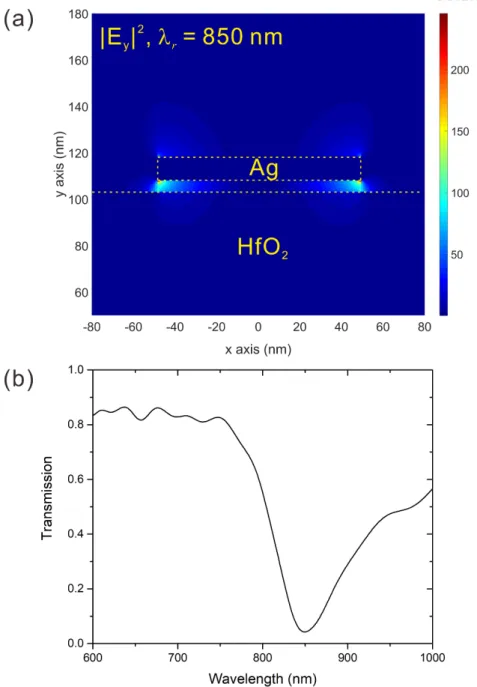
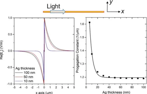
Calculated with the finite difference time domain (FDTD) method (FDTD Solutions, Lumerical Inc.). a) The Ey field distribution and (b) the propagation constant of the short-range surface plasmon polariton of a wavelength of 850 nm propagating along the ultrathin metal film. Example of the localized surface plasmon resonance around a thin metal strip (a) and the transmission spectrum with the rejection band (b) [4]. The yellow dotted line is the edge of the HfO2, and the Ag strip and the Ag layer are not indicated in the figure.
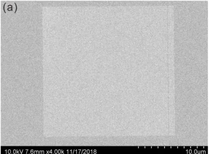
Carrier concentration distribution of the ITO tape when there is a bias between the Ag tape and the Ag layer. The black solid line is when the bias voltage is V = 0 V, and the red solid line is when the bias voltage is V = 46 V. Transmission spectrum when the bias voltage is between the Ag strip and the Ag layer. SEM image of the fabricated color filters. a) Picture of the UV-Vis microspectrometer and (b) schematic of the experimental setup. a).
The transmission image and (b) the reflection image of the UV-Vis microspectrometer patterns.
Introduction
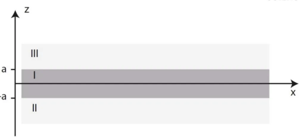
- Surface plasmon polariton at a metal film
- Short-range surface plasmon polariton in an ultrathin metal film
- Localized surface plasmon resonance in a thin metal strip
- Properties of infrared wireless communication
Using the vector identities with the assumption that a negligible change of the dielectric profile ε ε 𝐫 at distances on the order of an optical wavelength, the equation can be simplified to the central equation of the electromagnetic theory,. Assuming in general a harmonic time dependence 𝐄 𝐫, t 𝐄 𝐫 𝑒 of the electric field, equation (1.14) becomes,. Solving this equation gives two sets of stable solutions with different polarization properties of the propagating waves.
When the separation between adjacent interfaces is comparable to or smaller than the decay length of the surface mode, interactions between SPPs give rise to coupled modes. LRSPPs have the interesting property that as the thickness of the metal film decreases, the confinement of the SPP along with the metal film decreases as the mode evolves into a plane wave supported by the homogeneous dielectric medium and the propagation length of the LRSPP increases drastically . To achieve extreme isolation, SRSPP in an ultra-thin metal film and metal strips has been investigated.
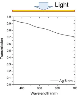
Ultra-thin metal film has been widely studied due to its characteristics; transparency in the visible and extreme mode limit with large spreading constants. The ultra-thin metal film with a thickness thinner than the penetration depth has high transparency in the visible regime. When a wave hits a metal, the size of the wave decreases exponentially from the surface of the metal.
Ey field distribution and (b) propagation constant of a short-range surface plasmon polariton with a wavelength of 850 nm propagating along an ultrathin metal film. When an ultrathin metal film exists, the electric field of the SRSPP mode can be confined to an extremely narrow region and its propagation constant increases, as shown in Figure 1-3. There are many devices based on ultrathin metal film, such as plasmonic color filters [3-5], visible light modulators [6] and metasurfaces [7].
In this thesis, a modulator composed of an ultra-thin metal film and a set of metal strips for a wavelength of 850 nm has been studied. 𝑁 𝑤 𝜑 𝑚𝜋 (2) where λr is a resonance wavelength, Ns is the effective index of the SRSPP, and 𝜑 is the phase shift caused by the reflection of the SRSPP at the strip edge. Thus, the direct pass rate of IR sources controls the modulation bandwidth of IR wireless communications.
The characteristics of the geometric parameters of the proposed modulator and the intensity modulation are investigated. Simple models of array of thin metal strips, subtractive color filters, have been experimented as a preliminary experiment of a future realization of the proposed modulator.
Optical and electrical characteristics of the proposed modulator
- Proposed modulator for IR wireless communications
- Properties of indium-tin-oxide (ITO)
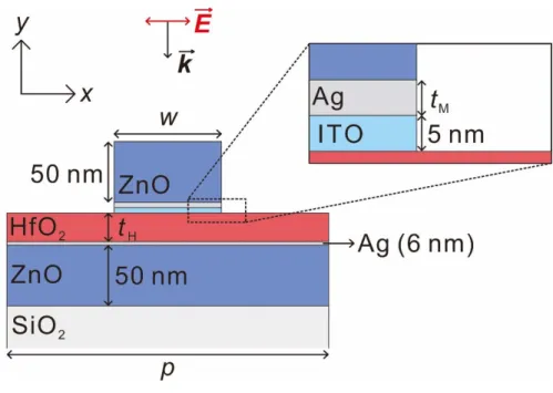
- Characteristics of the proposed structure
- Influence of geometrical parameters
- Electrically tunable ITO refractive index
- Intensity modulation at 850 nm
Then, the SRSPP wavelength is shifted around the Ag strip due to the change of the effective index of the SRSPP. When the refractive index of the ITO strip is adjusted, the LSPR wavelength is also adjusted as the effective index of the LSPR mode changes. The ITO strip is set to 5-nm-thick to achieve greater modulation considering the LSPR field distribution.
The transmission is higher than 80% out of the rejection band since the Ag layer is 6 nm thick, an ultra-thin metal film. Similarly, the influence of the strip width as shown in Figure 2-7 can also be explained by the FP relation. The voltage from 0 V to 46 V is applied to the Ag layer, and the voltage of the Ag strip is set to 0 V.
It results in a strong electric field at the edge of the ITO strip, as shown in Figure 2-11. To bring the carrier concentration to N cm-3 at the center of the ITO surface, a much larger voltage is required. The change of the refractive index of the ITO strip according to the change of the carrier concentration in the ITO strip.
These carrier concentration changes in the ITO tape cause the refractive index of the ITO tape to change. The refractive index at the center of the ITO surface decreases by 0.5 in Re[NITO] and increases by 0.1 in Im[NITO]. Since the index of refraction has changed, the effective index of the LSPR mode also changes.
The electric field of the LSPR, the resonance of the SRSPP, is strongly confined around the Ag strip. Thus, the effective index of SRSPP mode changes when the refractive index of the ITO changes. Even though the SRSPP electric field around the Ag strip decays rapidly, the change of the ITO refractive index affects the effective index of SRSPP since the ITO strip is only 5 nm thick.
To compare the modulation efficiency, the bias voltage is increased to 16 V where the carrier concentration of the ITO strip N cm-3. However, due to the strong interaction between the Ag strip and the Ag layer, the off-state transmission of the rejection band is enhanced.
![Figure 2-2. Example of electric field distribution as function of applied voltage. [20]](https://thumb-ap.123doks.com/thumbv2/123dokinfo/10514665.0/25.892.252.645.185.522/figure-example-electric-field-distribution-function-applied-voltage.webp)
Preliminary experiment
Fabrication of metal strip array
The metal strip consists of 2-nm-thick Cr on the bottom and 18-nm-thick Au on the top. For now, a strip width of 50 nm with a period of 150 nm strip series manufacturing is possible. This can be somewhat overcome with reducing the loading problem by using silver paste instead of carbon tape when attaching the sample to the SEM drill holder, and with depositing thicker Cr on the sample.
In the subtractive color filters, the rejection band is in the visible range, so that the color that has passed through the filter is visible. Since the LSPR around the thin metal strip causes the repulsion band in the transmission spectrum, the transmissive subtractive color filters can be made with a thin metal strip array. Therefore, for this experiment, the subtractive color filters are fabricated which have the repulsion band at λr = 600 nm.
To verify that the rejection band shifts with the different strip widths, metal strip arrays of w = 90 nm and w = 80 nm with the same period are also fabricated.
Subtractive color filter experiment
In the transmission image, the samples appear blue-green in color as they have a rejection band at λr = 600 nm, which corresponds to the red color. On the other hand, in the reflected image, the samples appear bright red in color as they have a resonant wavelength at λr = 600 nm. In addition, the region without patterns appears bright and dark in the transmission and reflection images, respectively.
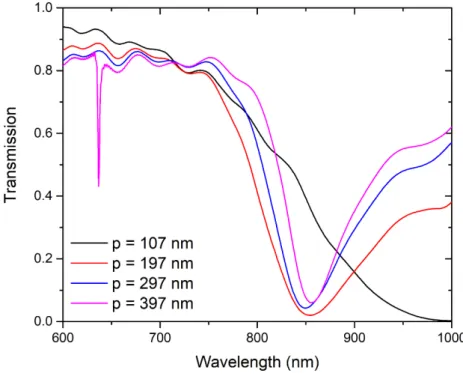
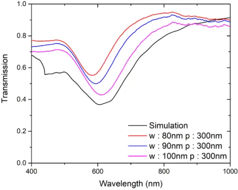
In the transmission spectrum, since the pattern-free region has no rejection band, almost all light can pass the filter. The black solid line shows the simulation result, and the red, blue and pink solid lines show the measurement results of the models when w = 100 nm and. In addition, the rejection band blue-shifts as the band width w decreases as explained by the FP relation.
Outside the rejection band, lower transmission on the left side than on the right side is due to the interband transition of Au. These results indicate that this preliminary experiment verifies the optical simulation results of the modulator. Reflectance spectrum cannot be obtained at the moment due to the polarizer setup of the microspectrometer.
Discussion
Conclusion
Polarization-independent plasmonic subtractive color filtering in ultrathin Ag nanodisks with high transmission. Applied Optics, vol. Active modulation of visible light with graphene-loaded ultrathin metal plasmonic antennas.” Scientific Reports, vol. Anomalous reflection in the ultra-thin nanostrip antenna caused by incident field and displacement current phase matching.” Journal of the Optical Society of America B, vol.
Resonantly suppressed transmission and anomalously enhanced light absorption in periodically modulated ultrathin metallic films,” Physical Review B, vol. Short-range surface plasmon polariton for ultra-low transmission through ultra-thin nanopatterned metal films. Experimental demonstration of a new indoor optical wireless localization system for high-speed personal networks.” Optics Letters, vol.
Dynamic Handover Load Balancing in Hybrid Li-Fi and Wi-Fi Networks.” Journal of Lightwave Technology, vol.
![Figure 1-4. Examples of the devices based on an ultrathin metal film. (a) Plasmonic color filter [3], (b) visible light modulator [6], and (c) metasurfaces [7]](https://thumb-ap.123doks.com/thumbv2/123dokinfo/10514665.0/20.892.155.741.850.1062/figure-examples-devices-ultrathin-plasmonic-visible-modulator-metasurfaces.webp)
![Figure 1-5. Example of the localized surface plasmon resonance around a thin metal strip (a) and the transmission spectrum with the rejection band (b) [4]](https://thumb-ap.123doks.com/thumbv2/123dokinfo/10514665.0/21.892.147.748.609.912/figure-example-localized-surface-resonance-transmission-spectrum-rejection.webp)
![Figure 1-6. Example of infrared (IR) wireless communication systems [18].](https://thumb-ap.123doks.com/thumbv2/123dokinfo/10514665.0/22.892.106.792.187.367/figure-example-infrared-ir-wireless-communication-systems-18.webp)