저작자표시-비영리-동일조건변경허락 2.0 대한민국 이용자는 아래의 조건을 따르는 경우에 한하여 자유롭게
l 이 저작물을 복제, 배포, 전송, 전시, 공연 및 방송할 수 있습니다. l 이차적 저작물을 작성할 수 있습니다.
다음과 같은 조건을 따라야 합니다:
l 귀하는, 이 저작물의 재이용이나 배포의 경우, 이 저작물에 적용된 이용허락조건 을 명확하게 나타내어야 합니다.
l 저작권자로부터 별도의 허가를 받으면 이러한 조건들은 적용되지 않습니다.
저작권법에 따른 이용자의 권리는 위의 내용에 의하여 영향을 받지 않습니다. 이것은 이용허락규약(Legal Code)을 이해하기 쉽게 요약한 것입니다.
Disclaimer
저작자표시. 귀하는 원저작자를 표시하여야 합니다.
비영리. 귀하는 이 저작물을 영리 목적으로 이용할 수 없습니다.
동일조건변경허락. 귀하가 이 저작물을 개작, 변형 또는 가공했을 경우 에는, 이 저작물과 동일한 이용허락조건하에서만 배포할 수 있습니다.
Doctoral Thesis
Yongchul Kim
Department of Chemistry
Ulsan National Institute of Science and Technology
2023
A Study on the Surface State of Catalytic Chemistry
Using First-Principles calculation
Yongchul Kim
Department of Chemistry
Ulsan National Institute of Science and Technology
A Study on the Surface State of Catalytic Chemistry
Using First-Principles calculation
i
Abstract
A catalyst refers to that accelerates a chemical reaction without being consumed during the chemical reactions. This property is usually referred to as the catalytic activity. For a multi- step chemical reaction with multiple possible products, a catalyst can promote the production of a specific chemical compound, which is related to the rate-determining step of the reaction.
Heterogeneous catalytic reactions mainly occur on the surface of solid catalysts with accompanying elementary surface chemical processes such as adsorption of reactants from a reaction mixture, surface diffusion and reaction of adsorbed species, and desorption of reaction products. The promotion of a chemical reaction is originated from the high reactivity of surface atoms that facilitates bond breaking and bond rearrangement of adsorbed molecules. In order to increase the yield of a desired reaction, the demand for catalysts showing high activity is growing throughout modern industries. Beyond simple chemical reactions, the complex and multi-step reactions have been important in various fields that require effective catalyst.
However, research is needed in many cases to understand the detailed bond rearrangement of the reaction on the catalyst surface or the diffusion or dissolution process of the interface. As the demand for catalyst design or material synthesis increases, the first-principles calculations are required to understand a detailed catalysis.
One area where catalyst is highly required is hydrogen production. As the use of fossil fuels increases, the world faces a climate crisis due to carbon dioxide emissions, and as a promising substitute for fossil fuels, hydrogen has emerged as a clean and renewable energy. In particular, green hydrogen production without CO2 emission can be achieved through electrocatalytic water splitting. In water splitting reactions, the commercial electrocatalysts composed of rare metals such as Ir, Pt and Ru has a problem with their price. Besides, sluggish multi-step oxygen evolution reaction (OER) is another hindrance for efficient water splitting. To overcome these problems, development of cheap electrocatalysts with high performance is necessary. First-principles calculations using density functional theory (DFT) has been used to describe and predict the intrinsic activity of catalysts. The adsorption energies of intermediates determine the activity of the catalyst. The surface electronic structure is highly correlated with intermediate species adsorption energies which determine the catalytic activity.
In Chapter 2, we investigated the influence of cation mixing on the oxygen evolution reaction (OER) activity of LaxSr1-xCoyFe1-yO3 (LSCF) double perovskite in the perspective of surface electronic structure. Based on projected density of states and wavefunction analysis, the minority spin dxy electrons of surface layer metal atoms are significant due to their stability, where the antibonding states between dxy and the lattice oxygen p become occupied when Co atoms with one d electron more than Fe are
ii
present. Thus, by additionally considering the dxy band center, surface electronic descriptor (E2p − 0.4 Edxy) excellently describes the binding energy of the OER intermediates and the stability against oxygen vacancy formation, which also explains the enhanced OER stability and efficient Fe–Co mixing. Based on the computational analysis, several efficient perovskite electrocatalysts were presented, and it was confirmed that the electronic structure analysis could provide guidance for electrocatalysts design.
Another area in which catalysts play an important role, is the synthesis and etching of low- dimensional carbon materials through the 3d transition metal surface. Graphene is produced from amorphous sp3 carbon through Ni junction, and the surface of diamond is etched under high-temperature conditions. In order to control these interfacial reactions, accurate understanding and mechanism analysis are required, and detailed bond dissociation and forming processes can be identified through first-principles DFT simulations.
In Chapter 3, we analyze the kinetics of dissolution of single crystal diamond (100) and (110),
“D(100)” and “D(110)”, into thin films of nickel (Ni) and cobalt (Co). This dissolution occurs at the metal-D(100) or metal-D(110) interface and was studied in the presence and also absence of water vapor at temperatures near 1000 ℃. Based on the first-principles calculation, the mechanism of why the diamond surface carbon can diffuse through Ni or Co despite the low activation energy of the reverse reaction were unveiled.
iii
iv
Contents
Abstract ... i
Contents ... iv
List of Figures ... vi
List of Tables ... xiv
I. Introduction ... 1
1.1 General Information ... 1
1.1.1 Water Splitting for Hydrogen Production ... 1
1.1.2 Carbon Control for Material Synthesis ... 3
1.2 DFT simulations for OER Electrocatalysts ... 4
1.2.1 Computational Standard Hydrogen Electrode ... 4
1.2.2 Electrochemical Half-Reaction of Water Splitting, OER ... 4
1.2.3 OER Electrolysis on Perovskite Oxide ... 6
1.3 Carbon Control via Metal Surface ... 8
1.3.1 Carbon Diffusion ... 8
1.3.2 Growth of Carbon ... 9
1.4 Outline of Dissertation ... 11
1.5 References ... 12
II. Theoretical Investigation for Rational Design of the OER Elecatalysts ... 14
2.1 Introduction ... 14
2.2 Methods ... 15
2.2.1 Calculation Information ... 15
2.2.2 Explicit Solvent and Minima Hopping Methods ... 16
2.3 Results and Discussion ... 18
2.3.1 OER Mechanism and Intermediates Binding Strength ... 18
2.3.2 Correlation of Surface Electronic Structure and Surface Stability ... 22
2.3.3 Descriptor (E2p – 0.4 Edxy) ... 26
2.3.4 OER activity and Electrocatalyst Design ... 30
2.4 Conclusion ... 37
2.5 References ... 38
III. DFT Simulation for the Interface Carbon Diffusion ... 42
3.1 Introduction ... 42
3.2 Methods ... 43
v
3.3 Results and Discussion ... 44
3.3.1 Experimental Findings ... 44
3.3.2 Theoretical Modeling of Reaction Pathways and Potential Energy Barriers ... 48
3.3.3 Surface Exchange Mechanism ... 55
3.4 Conclusion ... 57
3.5 References ... 58
IV. Summary ... 61
Appendix Acknowledgements ... 62
List of Publications ... 63
vi
List of Figures
Figure 1.1 Yearly evolution and percentage distribution of publications from 2000 to date containing terms ‘‘hydrogen’’ AND ‘‘storage’’ AND ‘‘material’’, ‘‘hydrogen’’ AND ‘‘energy storage system’’ NOT ‘‘tank’’, ‘‘hydrogen’’ AND ‘‘power-to-gas’’, ‘‘hydrogen’’ AND
‘‘transportation’’, ‘‘hydrogen’’ AND (‘‘co-generation’’ OR ‘‘tri-generation’’). The search was made on the 2th June 2020.Copyright © 2021 M. Yue et al. Published by Elsevier Ltd.4 Figure 1.2 Yearly evolution and percentage distribution of publications from 2000 to date
containing terms ‘‘hydrogen’’ AND (‘‘cost’’ OR ‘‘economy’’), ‘‘hydrogen’’ AND
‘‘efficiency’’, ‘‘hydrogen’’ AND (‘‘durability’’ OR ‘‘lifetime’’ OR ‘‘degradation’’). The search was made on the 2th June 2020. Copyright © 2021 M. Yue et al. Published by Elsevier Ltd.4
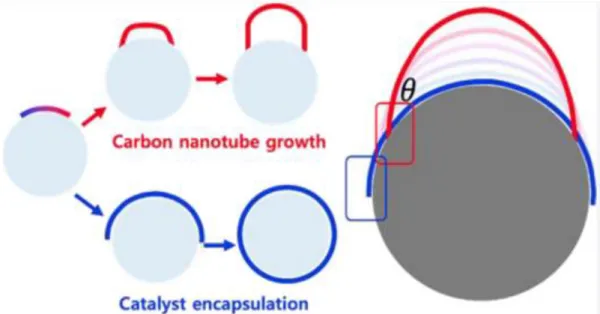
Figure 1.3 L. P. Ding et al. reveal the fundamental aspect of the CNT-catalyst interface, viz., that the interfacial energy of the CNT−catalyst edge is contact angle-dependent. This angle dependence can give a rationale why the CNTs grow.5 Copyright © 2022 American Chemical Society.
Figure 1.4 (a) Hydrogen evolution reaction (HER) and oxygen evolution reaction (OER) of electrocatalytic water splitting and (b) Schematic representation of HER and OER overpotentials.11 Copyright © 2021 Published by Elsevier B.V.
Figure 1.5 Conceptual illustration of concerted four step adsorbate evolution reaction (AEM) mechanism.
Figure 1.6 In Ni-based perovskite, schematic illustration of the competition between the Adsorbate Evolution Mechanism (AEM) and Lattice-Oxygen Participation Mechanism (LOM).14 Copyright © 2018 American Chemical Society.
Figure 1.7 Illustration of C dissolution at the interstitial (a) O-site and (b) T-site in bulk Ni.
Large balls denote Ni atoms and small balls denote C atoms.15 Copyright © 2006 Elsevier Ltd.
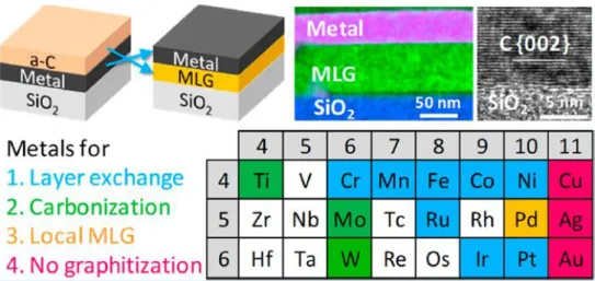
Figure 1.8 Some 3d transition metals can induce layer exchange to turn amorphous carbon into graphene.20 Copyright © 2018 American Chemical Society
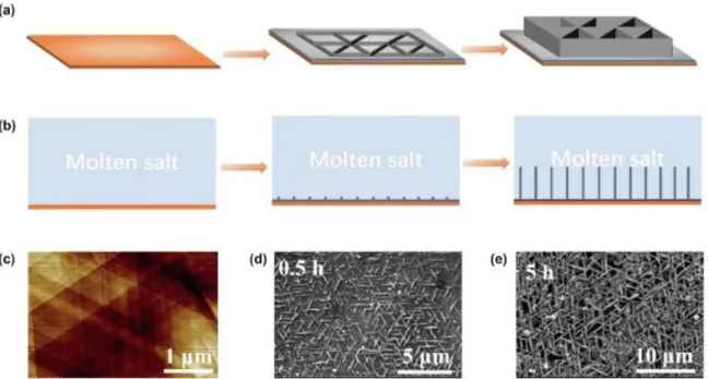
Figure 1.9 (a,b) Schematic representations of growth of CNWs. (c) AFM image of bare Cu (111) surface. (d, e) SEM images of CNWs deposited at -1.25 V for (d) 0.5 h and (e) 5h.7 Copyright
© 2022 Elsevier Ltd.
Figure 1.10 (a) The optimized structure of the Cu(111) with a two-atom step running along the
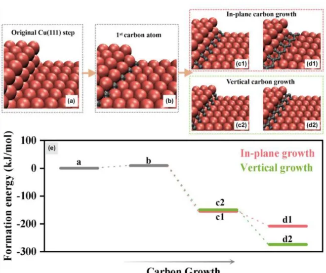
<110> slip direction; (b) The optimized structure of the first carbon atom adsorbed at an edge of the step and the lower terrace; The optimized structures following (c1 and d1) in-plane carbon growth or (c2 and d2) vertical carbon growth; (e) Calculated formation energy per carbon atom according to equations (1) and (2). (Each step shown corresponds to these structures: a, b, c1, d1, c2, d2).7 Copyright © 2022 Elsevier Ltd.
vii
Figure 2.1 Rock-salt ordered slab model of La0.5Sr0.5Co0.5Fe0.5O3. A- and B-site are described as highly isotropic chemical environment. Copyright © 2022 American Chemical Society.
Figure 2.2 Optimized LaCoO3 structure with the explicit solvent. The explicit water molecule initial positions were given by atomic simulation environment (ASE) package global optimization. *OH and *OOH intermediate form hydrogen bond with water molecule. The different colors indicate each atom (La = white, Co = blue, O = red, intermediate O = green, H = pink). Copyright © 2022 American Chemical Society.
Figure 2.3 According to the R. Jacob. report, catalytic activity of perovskite correlates with bulk oxygen p-band center. Reprinted from ref. 15. Copyright © 2019, American Chemical Society.
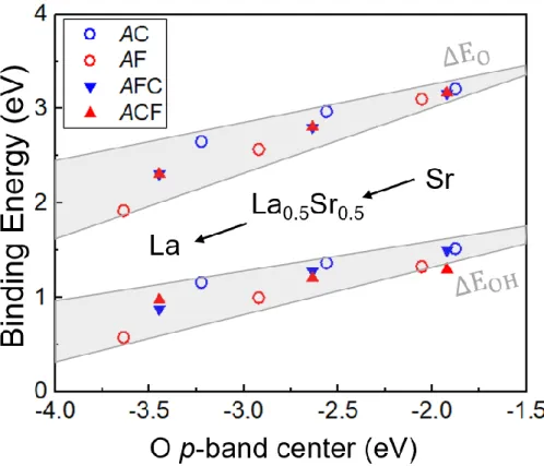
Figure 2.4 Calculated binding energies of HO* (∆EOH) and O* (∆EO) on the (001) surface as a function of O p-band center for LaxSr1-xCoyFe1-yO3 with x, y = 0.0, 0.5, or 1.0. The color of the symbols indicates the species of the active metal site (red = Fe and blue = Co). The binding energies of AFeO3 (AF) and ACoO3 (AC) are represented with open circles, where the mixed case (y = 0.5) are denoted by upward- and downward-facing triangles. Both of notation ACF and AFC represent ACo0.5Fe0.5O3 composition, the last abbreviation alphabet (C or F) indicates the active B-site element. Copyright © 2022 American Chemical Society.
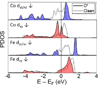
Figure 2.5 The PDOS of the minority spin dyz and dxy orbitals of the active metal site for LaBO3
before (Clean) and after adsorption of O (O*), which are represented by the dashed and solid lines, respectively. Copyright © 2022 American Chemical Society.
Figure 2.6 The dyz/xz minority spin projected band of LaCoO3 and LaFeO3 for clean surface and O*. In order to show some band characters, the wavefunctions of several representative bands related to dyz at the Γ point are also shown in left of each band. The abbreviation capital alphabet represents L = La, C = Co, F = Fe, respectively. The band of the entire slab is shown in gray, active site dyz/xz and the surface oxygen band are shown in blue and black, respectively.
After O was adsorbed to the surface, the band of intermediate O was shown in red. The wavefunction of each band shows that dyz/xz mainly forms a surface state before intermediate adsorption and mainly forms π bond with O after the adsorption. In O*, dyz/xz formed wavefunctions that mainly overlaps with O intermediate states, and it can be seen that it makes π-, π*-bond. Bonding wavefunction is indicated by a solid box, and antibonding is indicated by a dashed box. Copyright © 2022 American Chemical Society.
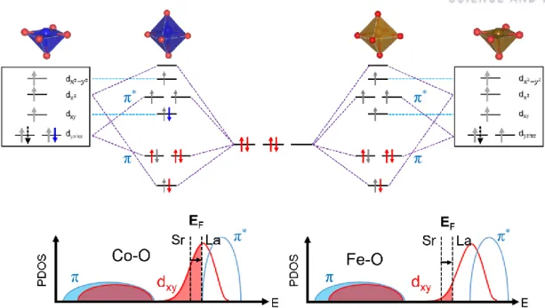
Figure 2.7 (Top) Orbital configurations of ACoO3 and AFeO3 for clean and O*. Before O intermediate adsorbed, the clean surface has C4v symmetry. The blue arrow indicates the additional electron in Co active site compared with Fe active site. The gray arrows represent the other electron from B metal and red arrows indicate the electrons from intermediate O. The black dashed arrow shows the variation of electron number from Sr to La A-site substitution.
(Bottom) The PDOSs after O adsorption are presented only for the minority spin dyz/xz (light
viii
blue sold line) or dxy (red solid line) orbitals in π hybridization with px/y of the adsorbate or surface-layer O, respectively, where the vertical dashed line denotes the Fermi level (EF) shifting rightward upon changing Sr to La, with the occupied states denoted by filled color for LaBO3.
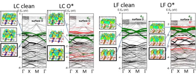
Figure 2.8 The dxy minority spin projected band of LaCoO3 and LaFeO3 for clean surface and O*. Except that dxy is expressed in green, the other notation and color is the same as in Figure 2.6. Through the wavefunction images, dxy electrons form a bond with surface oxygen, and it can be seen that there is almost no overlap with O intermediate states (red projected band).
Copyright © 2022 American Chemical Society.
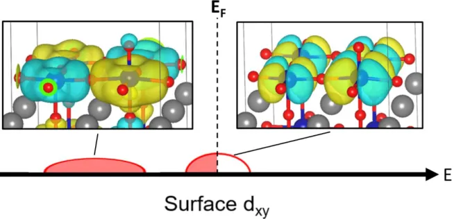
Figure 2.9 Schematic illustration of surface dxy projected DOS of LaCoO3 with its wavefunction image. The wavefunction image near the Fermi level shows that dxy and intermediate O of the active site metal have no overlap (which means non-bonding), and that dxy mainly has antibonding character with surface lattice oxygen. Since the dxy has the antibonding character with surface lattice oxygen, additional electron in Co active site can affect to the surface stability and the intermediate binding strength even though the dxy doesn’t form bonding nor antibonding with intermediate species.
Figure 2.10 The binding energies of HO* and O* as in Figure 2.4 plotted against a new descriptor (E2p − 0.4 Edxy). The color of the symbols indicates the species of the active metal site (red = Fe and blue = Co). The binding energies of AFeO3 (AF) and ACoO3 (AC) are represented with open circles, where the mixed case (y = 0.5) are denoted by upward- and downward-facing triangles. Both of notation ACF and AFC represent ACo0.5Fe0.5O3 composition, the last abbreviation alphabet (C or F) indicates the active B-site element. Copyright © 2022 American Chemical Society.
Figure 2.11 (a) Surface structure of the second reaction step (O*) in AEM (upper image) and O vacancy involved surface structure with adsorbate O (VO+OO*) in LOM (lower image). The green balls represent the adsorbate O and associated lattice O. (b) Correlation between the newly suggested descriptor (E2p − 0.4 Edxy) and the Gibbs free energy difference ∆G = G𝑉𝑂+OO∗− GO∗ of VO+OO* and O* for ABO3 without (open circle) or with (upper and lower triangle) Fe–Co mixing for the B-site. The blue and red colors denote Co and Fe for the active site metal, respectively. The variation of ΔG with the A-site composition, such as x = 0.0, 0.5, and 1.0 for LaxSr1-x, follows the lines with the associated color for the active site type. AEM is favored for a more positive value of ΔG (G𝑉𝑂+OO∗− GO∗). Copyright © 2022 American Chemical Society.
Figure 2.12 (a) Binding energies of HO* and O* versus the new bulk descriptor E2p − 0.4 Et2g, where E2p and Et2g are the O 2p band energy level and t2g minority spin band center relative to EF, respectively, from the 2 × 2 × 2 cubic supercell calculations. (b) The AEM overpotentials
ix
of AC, AF, AFC, and ACF (A = Sr, La0.5Sr0.5, and La) plotted against the descriptor (E2p − 0.4 Et2g). Lines in (a) and (b) are added for guidance. Copyright © 2022 American Chemical Society.
Figure 2.13 In LaxSr1-xCoyFe1-yO3 (x=0.0, 0.5, 1.0, y=0.0, 0.5), the OER overpotential is plotted by binding energy difference between O* and HO* (Δ𝐄𝐎 ― Δ𝐄𝐎𝐇). The OER overpotential is based on AEM 4 step reaction (Section 1.2.3). Copyright © 2022 American Chemical Society.
Figure 2.14 Gibbs free energy of HOO* plotted against the Gibbs free energy of HO* calculated for LaxSr1-xCoyFe1-yO3 (x, y = 0.0, 0.25, 0.5, 0.75, or 1.0) (a) without explicit solvent condition and (b) with explicit solvent. The solid lines indicate the lines fitting by (a) ΔGOOH = 0.82ΔGOH
+ 3.397 and (b) ΔGOOH = 0.79ΔGOH + 3.173. To differentiate the OER reaction path favored for each material, the AEM and LOM types are denoted by filled and open circles, respectively.
Copyright © 2022 American Chemical Society.
Figure 2.15 (a) Overpotential contour map based on the scaling relation (ΔGOOH = 0.79ΔGOH + 3.173). The gray filled circles and line correspond to LaxSr1-xFeO3 calculated for x = 0.0, 0.5, or 1.0 and the guidance to eye, respectively. Similarly, the black open circles and line denote the case for LaxSr1-xCo0.5Fe0.5O3. The former and latter are denoted as AF and ACF, respectively, with the left- and right-end corresponding to Sr and La, respectively, for the A- site. The pink star indicates the most optimal point with an overpotential of 0.21 V. The black dashed line represents the ΔGO = 3.0 eV corresponding to the boundary of the two regions favoring AEM (lower-right) and LOM (upperleft). (b) Overpotential contour map based on the scaling relation as same with (a). The gray filled circle and line show the points of LaxSr1- xCoO3 (x=0.0, 0.5, 1.0) and its trend line. Fe-Co half mixed cases are represented as the black open circle and the trend of the AFe0.5Co0.5O3 is denoted by the black solid line as denoted by AC and AFC. Among the 6 points, LSFC (𝜂LSFC = 0.43 V) is closest to the optimal point (pink star, 𝜼 = 0.21 V). Copyright © 2022 American Chemical Society.
Figure 2.16 Gibbs free energy difference (ΔG) as function of x and y in LaxSr1-xCoyFe1-yO3. Top boxes present the results for the Co active site, while the remaining bottom boxes present the results for the Fe active site. The highest ΔG is a PDS and the discrepancy between the highest free energy step and 1.23 V (gray dashed line) determines the theoretical overpotential. The lowest overpotential according to A variation is indicated by a gray double arrow in each B composition with its value. For all the plotted free energies, the water solvent is explicitly included. In each active site, the lowest overpotential is denoted by red rectangle. Copyright
© 2022 American Chemical Society.
Figure 2.17 (a) Oxygen evolution reaction via the lattice-oxygen participation mechanism on the LSC surface. Red, pink, bright green, and dark green spheres represent oxygen, hydrogen, lanthanum, and strontium atoms, respectively. The top-left, bottom-left, bottom-right, and top-
x
right structures indicate OH*, (VO+OO)*, (VO+OH)*, and (HO+OH)* adsorbed on the LSC (001) surface, respectively. Nature Communications, Copyright © 2021, Nam Khen Oh et al.
(b) Gibbs free energy difference (G𝑉O+OO∗− GOH) as function of suggested new descriptor (E2p
– 0.4 Edxy). The Gibbs free energy difference is mainly related to potential determining step (PDS) of the lattice oxygen participated mechanism (LOM). Black solid line indicates potential of 1.23 V which could be the reference for optimal LOM materials in order to satisfy the Sabatier principle. Copyright © 2022 American Chemical Society.
Figure 2.18 Calculated binding energies of O* as a function of (a) O p-band center and (b) new descriptor E2p - 0.4 Edxy. The binding energy for AFeO3/ACoO3 and ACoyFe1-yO3 (A=LaxSr1-x; x, y = 0.0, 0.5, 1.0) are shown in open circles and triangles, respectively. The color of open circles and triangles indicates the species of active metal site (red = Fe, blue = Co). The additional calculated binding energies of O* for LaCrO3 (pink star), LaMnO3 (purple star), LaNiO3 (gray star), LaCuO3 (brown star) and LaNi0.5Fe0.5O3 (gray and red open star) are shown together. In LaBO3 (B = Cr, Mn, Fe, Co, Ni, and Cu), surface B-atom dxy down spin orbital projected DOS for (c) clean surface and (d) O*. As O intermediate is adsorbed, dxy down orbital starts to be filled in Mn and completely filled in Ni. However, in Cr, dxy down orbital is not filled in both the clean surface and O*. Conversely, in Cu, even from the clean surface, dxy orbital is fully filled. This means that the Cr and Cu OER intermediate binding strengths are independent of dxy. This is the reason why LaCrO3 and LaCuO3 cannot be described by our new descriptor.
Figure 2.19 Based on our calculation results, the AEM and LOM boundary line according to A- /B-mixing is presented. The upper left green area composition is expected to follow LOM and the lower right purple area is expected to follow AEM. The dashed line in each area represents the line where optimal overpotential could appear. The A-mixing can correspond to the effect of hole (or electron) doping through the hetero stack, where the amount of non-local or free carriers determines the doping concentration. Whereas, the B-mixing can explain the local effect of oxygen vacancy as it affects the amount of local 3d electrons. The AEM optimal line is estimated from Figure 2.12b and the LOM optimal line is deducted by the Figure 2.17b results. (Reference information, [5], [43], [44])
Figure 3.1 (a) Raman spectra after experiment without water vapor that were measured at the open metal surface (upper spectrum) and at the diamond surface after removal of the Ni film (lower spectrum). (b) Schematic of the Ni−diamond system; the green arrows show the diffusion direction of the C atoms. (c) SEM image of the graphite film formed on the open Ni surface. (d) Raman spectra obtained after the experiment with water vapor present in the quartz chamber, which were measured at the open metal surface (upper spectrum) and at the diamond
xi
surface after the removal of the NixOy/Ni film (lower spectrum). (e) Schematic of C diffusion through a Ni film and oxidation of C atoms at the open Ni surface. (f) SEM image of the nickel (oxide) surface. Copyright © 2022, American Chemical Society.
Figure 3.2 (a, b) Arrhenius plots of the dissolution rates of single-crystal diamonds with (100) surfaces coated with a (a) 500 nm-thick Ni film and (b) 500 nm-thick Co film, at different water bubbler temperatures. (c, d) Arrhenius plots of the dissolution rates of single-crystal diamond with (110) surfaces coated with a (c) 500 nm-thick Ni film and (d) 500 nm-thick Co film, at different water bubbler temperatures. (e) Real-time residual gas analyzer (RGA) analysis of water vapor−Ni−diamond reaction products. (f) Schematic of diamond dissolution with water vapor present: the surface reaction [regime I when this is rate-limiting, step (iii)]
and the metal diamond interface where diamond dissolves into the metal through breaking of C−C bonds at the M−D interface [regime II when this is rate-limiting, step (i)]. Step (ii) represents diffusion of C atoms through the Ni film-this is never rate-limiting for our study.
Copyright © 2022, American Chemical Society.
Figure 3.3 (a,b) Potential energy curves calculated for (a) H2O molecule reacting with Ni(100) (green) or Co(100) (blue) and (b) for C−C bond breaking at the Ni(100)/D(100) (green) or Co(100)/D(100) (blue) interfaces. The corresponding atomic structures of the initial, intermediate, and final configurations are shown as insets. (c,d) Potential energy curves calculated for a C atom diffusing from (c) Ni(100)/D(100) interface (green) through the octahedral site (O*) or (d) Co(110)/D(110) interface (blue) through the tetrahedral site (T*).
The corresponding atomic structures of the initial, intermediate, and final configurations are shown as insets. Copyright © 2022, American Chemical Society.
Figure 3.4 (left) Potential energy curves for an H2O molecule reacting with the Ni(100) or Co(100) surfaces; (right) atomic structures of the initial physisorbed molecule (x= 0.0), the transition state (x= 0.4) and other intermediate configurations. Copyright © 2022, American Chemical Society.
Figure 3.5 Potential energy curve for the surface reaction on Ni(100). (a) Potential energy curve for C atom migration from an octahedral (O*) site at the subsurface to an O* site at the surface, as shown in the inserted schematic image, which shows the reaction process from x= 0.0 to 1.0 (1). The O atom migrates from the original O* site to the O* site that the C atom had occupied yielding formation of -Ni-C-O (2), followed by release of one CO into the atmosphere (3). (b) Potential energy curve for C atom migration from an O* site at the subsurface to an O* site at the surface, as shown in the inserted schematic diagram, which shows the reaction process from x= 0.0 to 1.0 (1). The O atom migrates from the original O*
site to an O* site that the C atom had occupied forming -Ni-C-O (2), followed by release of one CO into the atmosphere (3). Note that there are two possible paths for the migration of the
xii
O atom at the metal surface because there are two inequivalent half-octahedral sites that the C atom occupied relative to the position of the O atom at the surface. We calculated the two paths and provide the potential energy curve for both. The energy barriers at each step for these two paths are lower than the energy barrier of the surface reaction between a Ni atom and a H2O molecule. Copyright © 2022, American Chemical Society.
Figure 3.6 Potential energy curve for the surface reaction on Co(100). Potential energy curve for one C atom migration from an octahedral site (O*) at the subsurface to an O* site at the surface, as shown in the inserted schematic, which shows the reaction process from x= 0.0 to 1.0 (1).
The oxygen atom migrates from the original O* site to the O* site that the C atom had occupied and forms the -Co-C-O state (2), and the -Co-C-O state decomposes and releases a CO(g) molecule into the atmosphere (3). The path calculated is the same as that calculated in Figure 3.5a, which has a lower energy barrier in steps (1) and (2) compared with the energy barrier for steps (1) and (2) in Figure 3.5b. The energy barriers at each step for this path are lower than the energy barrier of the surface reaction between a Co atom and a H2O molecule.
Copyright © 2022, American Chemical Society.
Figure 3.7 (left) Potential energy curves for a H2O molecule reacting with the Ni(110) or Co(110) surface; (right) atomic structures of the initial physisorbed (x= 0.0) state, the transition state (x= 0.4) and other intermediate configurations. Copyright © 2022, American Chemical Society.
Figure 3.8 Potential energy curve for the surface reaction on (a) Ni(110) and (b) Co(110). One C atom jumps from an octahedral (O*) site at the subsurface to a tetrahedral (T*) site, then to the surface, as shown in the inserted schematic; from x= 0.0 to 1.0 (1), the O atom migrates from the original O* site to the T* site that the C atom occupied and forms -M-C-O (2), and the -M-C-O then releases a CO molecule into the atmosphere (3). Thus: From x= 0.0 to 1.0 the indicated C atom moves to the surface, from x= 1.0 to 2.0 a surface O atom and that same surface C atom migrate and react, and from x= 2.0 to 3.0 CO desorbs. The appearance of a C atom on the M(110) surface thus occurs in two steps, as shown in the inserted schematic: from x= 0.0 to 0.5, a C atom in the sublayer moves to a T* site just below the open surface, and from x= 0.5 to 1.0, this C atom moves from the T* site to the open surface. For Ni(110), this diffusion from subsurface to the surface has the highest energy barrier (161 kJ/mol) when the C atom migrates to the open surface. For Co(110) the highest energy barrier (165 kJ/mol) is for the C atom passing through the T* site. Copyright © 2022, American Chemical Society.
Figure 3.9 (left) Potential energy curves for C atom diffusion at the Ni(110)/D(110) (green curve) and Co(110)/D(110) (blue curve) interfaces through the (a) tetrahedral and (b) octahedral interfacial sites; (right) atomic structures of the initial (x= 0.0), intermediate (x= 0.2, 0.4, 0.6, and 0.8), and final (x= 1.0) configurations. Copyright © 2022 American Chemical Society.
xiii
Figure 3.10 Potential energy curves of carbon diffusion barriers in fcc-Ni and fcc-Co. The C atom diffuses from an octahedral site to a tetrahedral site, then back to the octahedral site (O* → T*
→ O*). We show the C atom diffusion energy barrier from the O* site to T* site only, due to symmetry. Copyright © 2022 American Chemical Society.
Figure 3.11 (left) Potential energy curves for C atom diffusion at the Ni(100)/D(100) (green curve) and Co(100)/D(100) (blue curve) interfaces; (right) atomic structures of the initial (x= 0.0), intermediate, and final (x= 1.0) configurations. Copyright © 2022 American Chemical Society.
Figure 3.12 (a) Schematic comparison of interface dissolution and bulk FCC metal carbon diffusion. Due to the higher activation barrier of bulk diffusion, backward reaction may occur in this scheme. (b) Actual calculated activation barrier (T = 1386 K) of the process which is described in (a). Red circle indicates the surface Ni atom that move onto the carbon vacancy site in diamond. The first bulk carbon diffusion shows very low activation barrier (15.4 kJ/mol) compared to the reverse reaction barrier of interface carbon dissolution.
Figure 3.13 The location of transferred Ni at (left) the bird-eye view, and (right) bottom-up direction view.
xiv
List of Tables
Table 2.1 The solvation free energy among the SC, SF, LC and LF. In our results, we applied the solvation energy of LaxSr1-xBO3 as function of x which is denoted in eq (2.5). (Unit: eV) Copyright © 2022 American Chemical Society.
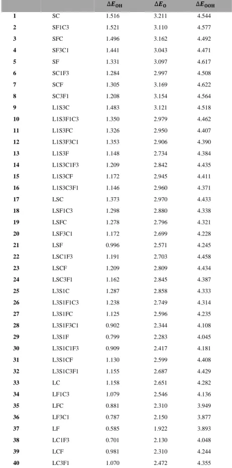
Table 2.2 Intermediate binding energy table. For convenience, like La0.25Sr0.75Co0.75Fe0.25O3, 1:3 ratio mixing of A-/B-site is expressed as L1S3C3F1 and the last abbreviation indicates the active B-site metal. (Unit: eV) Copyright © 2022 American Chemical Society.
Table 2.3 Gibbs free energy table with explicit solvent. The abbreviation capital alphabet represents L = La, S = Sr, C = Co, F = Fe. For convenience, like La0.25Sr0.75Co0.75Fe0.25O3, 1:3 ratio mixing of A-/B-site is expressed as L1S3C3F1 and the last abbreviation indicates the active B-site metal. (Unit: eV) Copyright © 2022 American Chemical Society.
Table 3.1 The detailed parameters of the simulation model. Copyright © 2022, American Chemical Society.
Table 3.2 ∆𝐻‡ and Prefactor A Values, from a Study of the Dissolution of D(100) and D(110) Coated with a 500 nm-Thick Ni or Co Film. Copyright © 2022, American Chemical Society.
Table 3.3 Energy Barrier Values (kJ/mol) Describing the Formation of −Ni−C−O or
−Co−C−O States on Ni/Co(100) and Ni/Co(110) Surfaces and the Decomposition to Release CO into the Gas Phase. Copyright © 2022, American Chemical Society.
1
I. Introduction
1.1 General Information
Since the industrial use of catalysts in the production of sulfuric acid by John Roebuck in 1746, catalysts are used in many industries by lowering the potential energy barrier of difficult or necessary reactions and by increasing the yield of products. Catalysts are used for biofuel1, hydrocarbon reforming2, water splitting3, nitrogen oxide and fine dust removal, material synthesis, etc., and their usage is increasing. In order to find and utilize new catalysts, it is necessary to know how the catalyst forms and breaks bonds with chemicals and what physical properties are important to be controlled.
1.1.1 Water Splitting for Hydrogen Production
Recently, theoretical research is being actively conducted in the catalyst chemistry used in eco-friendly energy production and synthesis of new materials. With the increasing demand for sustainable energy, human beings put forward higher requirements for the preparation of clean energy.
For an alternative to fossil fuels, hydrogen production is in the limelight. As shown in Figure 1.1, since 2000 hydrogen-related publications have grown very rapidly.4 Most of them were studies on materials (deep blue) or systems (orange) that store hydrogen itself, but since 2010, research on power-to-gas (gray) has increased a lot. Research on hydrogen is receiving great attention as a means to effectively store electricity, and the most interesting research keyword for hydrogen powered systems was efficiency (Figure 1.2).
Electrocatalytic water splitting has become a promising way to solve the energy crisis because of the characteristics of high efficiency and cleanliness. The catalyst of oxygen evolution reaction (OER), an important part of electrocatalytic water splitting, plays a critical role in water splitting to increase reaction kinetics, efficiency, and reaction selectivity. Due to its importance, the development of OER electrocatalysts is required.
2
Figure 1.1 Yearly evolution and percentage distribution of publications from 2000 to date containing terms ‘‘hydrogen’’ AND ‘‘storage’’ AND ‘‘material’’, ‘‘hydrogen’’ AND ‘‘energy storage system’’
NOT ‘‘tank’’, ‘‘hydrogen’’ AND ‘‘power-to-gas’’, ‘‘hydrogen’’ AND ‘‘transportation’’, ‘‘hydrogen’’
AND (‘‘co-generation’’ OR ‘‘tri-generation’’). The search was made on the 2th June 2020.Copyright
© 2021 M. Yue et al. Published by Elsevier Ltd.4
Figure 1.2 Yearly evolution and percentage distribution of publications from 2000 to date containing terms ‘‘hydrogen’’ AND (‘‘cost’’ OR ‘‘economy’’), ‘‘hydrogen’’ AND ‘‘efficiency’’, ‘‘hydrogen’’
AND (‘‘durability’’ OR ‘‘lifetime’’ OR ‘‘degradation’’). The search was made on the 2th June 2020.
Copyright © 2021 M. Yue et al. Published by Elsevier Ltd.4
3 1.1.2 Carbon Control for Material Synthesis
Catalysts are important in the synthesis of carbon materials. An advantage of carbon materials is that they can be configured in a variety of ways from simple graphite sp2 structure to complex bio- organic molecules. In addition, there are various allotropes made only of carbon, such as diamond, graphite, lonsdaleite, Buckminsterfullerene, C540, C70, amorphous carbon, and carbon nanotube. Aside from the possibilities of various carbon materials, it is very difficult to synthesize and control the structure of a desired material. It has been carried out through theoretical and experimental research for the synthesis of practical materials. For instance, the mechanism of forming the carbon nanotubes (CNTs) has been revealed, recently.5 Through the density functional theory (DFT) simulations, L. P.
Ding et al. found that the CNT-catalyst interface has an important role in CNT growth (Figure 1.3).
Several experimental and theoretical collaborations have revealed the fabrication of graphene flakes6 or graphene nanowall7 on the metal surface edge. For the development of new carbon materials, understanding the mechanism of bond breaking and formation through metal catalysis becomes important.
Figure 1.3 L. P. Ding et al. reveal the fundamental aspect of the CNT-catalyst interface, viz., that the interfacial energy of the CNT−catalyst edge is contact angle-dependent. This angle dependence can give a rationale why the CNTs grow.5 Copyright © 2022 American Chemical Society.
4 1.2 DFT simulations for OER Electrocatalysts
To develop a high-performance electrocatalyst, we can increase the intrinsic activity of the catalyst or increase the number of active sites. The density functional theory (DFT) simulation can give a rationale of the intrinsic activity of catalyst by showing the adsorption energies and activation energies of the reactions.8,9 As suggested by Nørskov, the theoretical activity of electrocatalyst can be obtained from Gibbs free energy of the reaction intermediates.10
1.2.1 Computational Standard Hydrogen Electrode
The computational standard hydrogen electrode (CHE) suggested by Nørskov et al.10 is extensively used to calculate theoretical electrochemical potentials based on the DFT. According to CHE method, the hydrogen electrode is assumed to be in equilibrium, i.e. the solvated protons and electrons are in equilibrium with the hydrogen in the gas phase:
𝐻+(𝑎𝑞) + 𝑒−⇄1
2𝐻2(𝑔) (1.1) 𝜇𝐻++ 𝜇𝑒− = 1/2𝜇𝐻2(𝑔) (1.2)
The chemical potential of proton, electron and hydrogen as follows:
𝜇𝐻+ = 𝜇𝐻0++ 𝑘𝐵𝑇ln𝑎𝐻+ (1.3) 𝜇𝑒− = 𝜇𝑒0−− 𝑒𝑈 (1.4) 𝜇𝐻2(𝑔)= 𝜇𝐻02(𝑔)+ 𝑘𝐵𝑇ln𝑝𝐻2 (1.5)
where 𝑎𝐻+ represents the activity of the protons, 𝑒𝑈 represents the shift in electron energy when a bias is applied and 𝑝𝐻2 is the partial pressure of hydrogen. 𝜇𝐻0+
, 𝜇𝑒0−, 𝜇𝐻02(𝑔) represent the chemical potential of protons, electrons and hydrogen at standard conditions (𝑝𝐻2 = 1 bar, 𝑎𝐻+ = 1, T = 298.15 K). Therefore, the relation can be written as:
𝜇𝐻0++ 𝜇𝑒0− =1
2𝜇𝐻02(𝑔) (1.6)
Then, we can calculate 𝜇𝐻02(𝑔) as the Gibbs free energies of hydrogen gas:
𝐺𝐻2 = 𝐸𝐻𝐷𝐹𝑇2 + 𝑍𝑃𝐸 − 𝑇𝑆 (1.7)
where the 𝑍𝑃𝐸 and 𝑆 indicate zero-point energy and calculated entropy of the hydrogen.
1.2.2 Electrochemical Half-Reaction of Water Splitting, OER
Based on the CHE method, the theoretical reaction barrier of electrochemical reactions can be calculated, which is called as overpotential. In water splitting, there are two half-reactions. One is the hydrogen evolution reaction (HER) and the other one is the oxygen evolution reaction (OER) which generates hydrogen molecule and oxygen molecule, respectively. From an electrochemical point of view, the standard reduction potential for water splitting is 1.23 V, but in reality a higher voltage is
5
required for the electrochemical reaction and the additional voltage is called as overpotential. As described in Figure 1.4, each half-reaction has its overpotential and the total overpotential of water splitting is given by:
𝜂𝑤𝑎𝑡𝑒𝑟−𝑠𝑝𝑙𝑖𝑡𝑡𝑖𝑛𝑔= 𝜂𝐻𝐸𝑅+ 𝜂𝑂𝐸𝑅 (1.8)
Figure 1.4 (a) Hydrogen evolution reaction (HER) and oxygen evolution reaction (OER) of electrocatalytic water splitting and (b) Schematic representation of HER and OER overpotentials.11 Copyright © 2021 Published by Elsevier B.V.
Appropriate electrochemical catalysts are required to minimize the overpotential. However, the overpotential mainly increases due to the sluggish OER that accompanies the multi-step reaction (see Section 1.2.3). Therefore, a good OER electrocatalyst to be applied to the anode is necessary.
6 1.2.3 OER Electrolysis on Perovskite Oxide
Figure 1.5 Conceptual illustration of concerted four step adsorbate evolution reaction (AEM) mechanism.
As introduced by I. C. Man et al.,12 the oxygen evolution reaction follows the four concerted reaction path on the electrocatalyst surface as followed:
∗ +𝐻2𝑂 ⇄ ∗ 𝑂𝐻 + 𝐻++ 𝑒− (1.9)
∗ 𝑂𝐻 ⇄∗ 𝑂 + 𝐻++ 𝑒− (1.10)
∗ 𝑂 + 𝐻2𝑂 ⇄∗ 𝑂𝑂𝐻 + 𝐻++ 𝑒− (1.11)
∗ 𝑂𝑂𝐻 ⇄∗ +𝑂2(𝑔) + 𝐻++ 𝑒− (1.12)
The four step reaction is called the adsorbate evolution reaction (AEM) and mainly occurs on the surface of a metal oxide catalyst (Figure 1.5). AEM is often seen on ABO3 perovskite oxide surface.
Using CHE, which we discussed in Section 1.2.1, we can calculate the Gibbs free energy of each step of the OER of the perovskite surface. Starting with eq (1.2), we postulate the OER at standard conditions (U = 0V, pH = 0, p = 1 bar, T = 298.15K) and chemical potential of hydrogen molecule and water molecule are approximately equal to DFT total energies where ZPE indicates zero-point energy of denoted molecules.
𝜇𝐻2(𝑔)= 𝐸𝐷𝐹𝑇𝐻2(𝑔)+ 𝑍𝑃𝐸𝐻2(𝑔)− 𝑇𝑆𝐻02(𝑔) (6) 𝜇𝐻2𝑂(𝑔)= 𝐸𝐷𝐹𝑇𝐻2𝑂(𝑔)+ 𝑍𝑃𝐸𝐻2𝑂(𝑔)− 𝑇𝑆𝐻02𝑂(𝑔) (7)
Thereby the free energies of (1), (2), (3), and (4) are given by followed paragraph:
Δ𝐺1 = 𝐺∗𝑂𝐻+ 𝜇𝐻++ 𝜇𝑒− − 𝐺∗− 𝜇𝐻2𝑂 (8) 𝐺∗𝑂𝐻 = 𝐸𝐷𝐹𝑇∗𝑂𝐻+ 𝑍𝑃𝐸∗𝑂𝐻− 𝑇𝑆∗𝑂𝐻0 (9) 𝐺∗= 𝐸𝐷𝐹𝑇∗ (10)
From equation (5), (6), (7), (9), and (10), Δ𝐺1 is given by:
7 Δ𝐺1 = 𝐸𝐷𝐹𝑇∗𝑂𝐻+1
2𝐸𝐷𝐹𝑇𝐻2(𝑔)− 𝐸𝐷𝐹𝑇∗ − 𝐸𝐷𝐹𝑇𝐻2𝑂(𝑔)+ ∆𝑍𝑃𝐸 − 𝑇∆𝑆0 (11) As similar way, other reactions are:
Δ𝐺2= 𝐺∗𝑂+ 𝜇𝐻++ 𝜇𝑒−− 𝐺∗𝑂𝐻 (12) Δ𝐺2= 𝐸𝐷𝐹𝑇∗𝑂 +1
2𝐸𝐷𝐹𝑇𝐻2(𝑔)− 𝐸𝐷𝐹𝑇∗𝑂𝐻+ ∆𝑍𝑃𝐸 − 𝑇∆𝑆0 (13) Δ𝐺3= 𝐺∗𝑂𝑂𝐻+ 𝜇𝐻++ 𝜇𝑒−− 𝐺∗𝑂− 𝜇𝐻2𝑂 (14) Δ𝐺3= 𝐸𝐷𝐹𝑇∗𝑂𝑂𝐻+1
2𝐸𝐷𝐹𝑇𝐻2(𝑔)− 𝐸𝐷𝐹𝑇∗𝑂 − 𝐸𝐷𝐹𝑇𝐻2𝑂(𝑔)+ ∆𝑍𝑃𝐸 − 𝑇∆𝑆0 (15) Δ𝐺4 = 𝐺∗+ 𝐺𝑂2(𝑔)+ 𝜇𝐻++ 𝜇𝑒−− 𝐺∗𝑂𝑂𝐻 (16)
Δ𝐺4 = 𝐸𝐷𝐹𝑇∗ − 𝐸𝐷𝐹𝑇∗𝑂𝑂𝐻+ 2𝐸𝐷𝐹𝑇𝐻2𝑂(𝑔)−1
2𝐸𝐷𝐹𝑇𝐻2(𝑔)+ 4.92 + ∆𝑍𝑃𝐸 − 𝑇∆𝑆0 (17) DFT intermediate binding energies are given by:
∆𝐸𝑂𝐻= 𝐸𝐷𝐹𝑇∗𝑂𝐻− 𝐸𝐷𝐹𝑇∗ +1
2𝐸𝐷𝐹𝑇𝐻2(𝑔)− 𝐸𝐷𝐹𝑇𝐻2𝑂(𝑔) (18)
∆𝐸𝑂 = 𝐸𝐷𝐹𝑇∗𝑂 − 𝐸𝐷𝐹𝑇∗ + 𝐸𝐷𝐹𝑇𝐻2(𝑔)− 𝐸𝐷𝐹𝑇𝐻2𝑂(𝑔) (19)
∆𝐸𝑂𝑂𝐻 = 𝐸𝐷𝐹𝑇∗𝑂𝑂𝐻− 𝐸𝐷𝐹𝑇∗ +3
2𝐸𝐷𝐹𝑇𝐻2(𝑔)− 2𝐸𝐷𝐹𝑇𝐻2𝑂(𝑔) (20)
However, another mechanism has also been suggested for ABO3 perovskite.13 When the oxygen in the lattice of ABO3 is unstable, the lattice oxygen on the surface also participates in the OER reaction as described in Figure 1.6 and the mechanism is called the lattice oxygen mechanism (LOM).
It can be assumed that the stability of surface lattice oxygen determines the mechanism, and when designing an OER catalyst, it is necessary to quickly determine which mechanism to follow. The Gibbs free energy in each state can be obtained from LOM as well as from AEM.
Figure 1.6 In Ni-based perovskite, schematic illustration of the competition between the Adsorbate Evolution Mechanism (AEM) and Lattice-Oxygen Participation Mechanism (LOM).14 Copyright © 2018 American Chemical Society.
8 1.3 Carbon Control via Metal Surface
Various attempts have been made to control through the metal surface for the synthesis of carbon materials.5,6,7 Nowadays, understanding the interaction between metal surfaces and carbon through theoretical research is a very important task.
1.3.1 Carbon Diffusion
An example of the simplest computational approach is the study of the kinetics of carbon diffusion in bulk metal such as Ni, Fe15-18 and grain boundary.19 The carbon diffusion activation barrier shown by DFT simulations in FCC bulk metals appeared when the carbon moved from octahedral site (Figure 1.7a) to tetrahedral site (Figure 1.7b). Carbon diffusion through metal can be another graphene synthesis method without exfoliation technique, where amorphous carbon diffuses inside the 3d transition metal to form multilayer graphene on the opposite side which is called layer-exchange growth of multilayer graphene (Figure 1.8).20 There is a possibility that it can be used for synthesis technique via carbon diffusion in 3d transition metals.
Figure 1.7 Illustration of C dissolution at the interstitial (a) O-site and (b) T-site in bulk Ni. Large balls denote Ni atoms and small balls denote C atoms.15 Copyright © 2006 Elsevier Ltd.
Figure 1.8 Some 3d transition metals can induce layer exchange to turn amorphous carbon into graphene.20 Copyright © 2018 American Chemical Society.
9 1.3.2 Growth of Carbon
A carbon material synthesis method via carbon growth with metal surface as a starting site has been studied as discussed in Section 1.1.2. Carbon materials are made by initiating and growing on the terrace or step edge of the metal surface. Recently, the cause of CNTs growth has been discovered5, and silmilarly, we revealed the reason why the formation of graphene nanowalls(Figure 1.9, 1.10) occur along the Cu(111) edge directions.7 Being able to initiate carbon growth along the metal edge direction can suggest a new direction for material synthesis.
Figure 1.9 (a,b) Schematic representations of growth of CNWs. (c) AFM image of bare Cu (111) surface. (d, e) SEM images of CNWs deposited at -1.25 V for (d) 0.5 h and (e) 5h.7 Copyright © 2022 Elsevier Ltd.
10
Figure 1.10 (a) The optimized structure of the Cu(111) with a two-atom step running along the <110>
slip direction; (b) The optimized structure of the first carbon atom adsorbed at an edge of the step and the lower terrace; The optimized structures following (c1 and d1) in-plane carbon growth or (c2 and d2) vertical carbon growth; (e) Calculated formation energy per carbon atom according to equations (1) and (2). (Each step shown corresponds to these structures: a, b, c1, d1, c2, d2).7 Copyright © 2022 Elsevier Ltd.
11 1.4 Outline of Dissertation
In this dissertation, the reason why metal oxides or surfaces of metals used as catalysts form bonds and induce chemical deformation is explored through computational research.
In Chapter 2, through DFT calculations, we reveal the physical origins that determine the catalystic activity in the LaxSr1-xCoyFe1-yO3 (LSCF) double perovskite oxide (AA’BB’O6) structure used as an OER electrocatalyst, and suggest a way to design a highly efficient catalyst based on theoretical analysis. Furthermore, by closely analyzing the mixing effect of A-site and B-site, we propose a new descriptor that expresses the electrocatalyst activity well and present the possibility of material design that goes beyond Fe-Co mixing.
In chapter 3, the mechanism of carbon dissolution and diffusion at the junction of diamond and metal was revealed, and the thermodynamically expressed enthalpy was identified through computational research. In addition, the surface exchange mechanism by which the surface carbon of diamond can dissolve into the FCC Ni and Co surface was revealed.
12 1.5 References
(1) Mortensen, P. M.; Grunwaldt, J. D.; Jensenm P. A.; Knudsen, K. G.; Jensen, A. D. A review of catalytic upgrading of bio-oil to engine fuels. Applied Catalysis A: General 2011, 407, 1–19.
(2) Cortright, R. D.; Davda, R. R.; Dumesic, J. A. Hydrogen from catalytic reforming of biomass- derived hydrocarbons in liquid water. Nature, 2002, 418, 964–967.
(3) McCrory, C. C. L.; Jung, S.; Peters, J. C.; Jaramillo, T. F. Benchmarking Heterogeneous Electrocatalysts for the Oxygen Evolution Reaction J. Am. Chem. Soc. 2013, 135, 45, 16977–16987.
(4) Yue, M.; Lambert, H.; Pahon, E.; Roche, R.; Jemei, S.; Hissel, D. Hydrogen energy systems:
A critical review of technologies, applications, trends and challenges, Renewable and Sustainable Energy Reviews, 2021,146, 111180.
(5) Ding, L. P.; McLean, B.; Xu, Z.; Kong, X.; Hedman, D.; Qiu, L.; Page, A. J.; Ding, F. Why Carbon Nanotubes Grow. J. Am. Chem. Soc. 2022, 144, 5606−5613.
(6) Yuan, Q.; Yakobson, B. I.; Ding, F. Edge-Catalyst Wetting and Orientation Control of Graphene Growth by Chemical Vapor Deposition Growth. J. Phys. Chem. Lett. 2014, 5, 3093−3099.
(7) Wang, M.; Kim, Y.; Zhang, L.; Seong, W. K.; Kim, M.; Chatterjee, S.; Wang, M.; Li, Y.;
Bakharev, P. V.; Lee, G. S.; Lee, S. H.; Ruoff, R. S. Controllable electrodeposition of ordered carbon nanowalls on Cu(111) substrates. Materials Today 2022, 57, 75-83.
(8) Hammer, B.; Nørskov, J. K. Theoretical surface science and catalysis – Calculations and concepts, Advances in Catalysis, 2000, 45, 71-129.
(9) Bligaard, T.; Nørskov, J. K. Heterogeneous Catalysis. Chemical Bonding at Surfaces and Interfaces; Nilsson, A.; Pettersson, L. G. M.; Nørskov, J. K., Eds.; Elsevier: Amsterdam, 2008; p 255- 321.
(10) Nørskov, J. K.; Rossmeisl, J.; Logadottir, A.; Lindqvist, L.; Kitchin, J. R.; Bligaard, T.;
Jónsson, H. Origin of the Overpotential for Oxygen Reduction at a Fuel-Cell Cathode. J. Phys. Chem.
B 2004, 108, 46, 17886–17892.
(11) Li, X. P.; Huang, C.; Han, W. K.; Ouyang, T.; Liu, Z. Q. Transition metal-based electrocatalysts for overall water splitting. Chinese Chemical Letters, 2021, 32, 2597–2616.
(12) Man, I. C.; Su, H. Y.; Calle-Vallejo, F.; Hansen, H. A.; Martínez, J. I.; Inoglu, N. G.; Kitchin, J.; Jaramillo, T. F.; Nørskov, J. K.; Rossmeisl, J. Universality in Oxygen Evolution Electrocatalysis on Oxide Surfaces. ChemCatChem 2011, 3 (7), 1159–1165.
(13) Grimaud, A.; Diaz-Morales, O.; Han, B.; Hong, W. T.; Lee, Y. L.; Giordano, L.; Stoerzinger, K. A.; Koper, M. T. M.; Shao-Horn, Y. Activating Lattice Oxygen Redox Reactions in Metal Oxides to Catalyse Oxygen Evolution. Nat. Chem. 2017, 9 (5), 457–465.
(14) Yoo, J. S.; Rong, X.; Liu, Y.; Kolpak, A. M. Role of Lattice Oxygen Participation in Understanding Trends in the Oxygen Evolution Reaction on Perovskites. ACS Catal. 2018, 8, 5, 4628–
4636.
13
(15) Zhu, Y.; Dai, Y.; Chen, D.; Yuan, W. First-principles study of carbon diffusion in bulk nickel during the growth of fishbone-type carbon nanofibers, Carbon, 2007, 45, 1, 21-27.
(16) Jiang, D. E.; Carter, E. A. Carbon dissolution and diffusion in ferrite and austenite from first principles. Phys. Rev. B 2003, 67, 214103.
(17) Massaro, T. A.; Petersen, E. E. Bulk Diffusion of Carbon‐14 through Polycrystalline Nickel Foil between 350 and 700°C. Journal of Applied Physics 1971, 42, 5534.
(18) Wiltner, A.; Linsmeier, Ch.; Jacob, T. Carbon reaction and diffusion on Ni(111), Ni(100), and Fe(110): Kinetic parameters from x-ray photoelectron spectroscopy and density functional theory analysis. THE JOURNAL OF CHEMICAL PHYSICS 2008, 129, 084704.
(19) Siegel, D. J.; Hamilton, J.C. Computational study of carbon segregation and diffusion within a nickel grain boundary. Acta Materialia 2005, 53, 87–96.
(20) Nakajima, Y.; Murata, H.; Saitoh, N.; Yoshizawa, N.; Suemasu, T.; Toko, K. Metal Catalysts for Layer-Exchange Growth of Multilayer Graphene. ACS Appl. Mater. Interfaces 2018, 10, 41664−41669.
14
II. Theoretical Investigation for Rational Design of the Perovskite Oxide OER Elecatalysts
This chapter includes the materials of:
Unveiling surface electronic descriptor for Fe-Co mixing enhanced stability and efficiency of perovskite oxygen evolution electrocatalysts.
Yongchul Kim, Miran Ha, Anand Rohit, Mohammad Zafari, Jeong Min Baik, Hyesung Park, Geunsik Lee*, Submitted.
2.1 Introduction
In order to produce hydrogen without emitting greenhouse gases, electrochemical splitting of water is a desirable way for sustainable energy storage. However, it is required improving in efficiency and stability of eletrocatalysts composed of earth abundant elements for large-scale hydrogen production. The state-of-the-art electrocatalysts have been consisted of noble-metal, such as Pt, IrO2, or RuO2 for the hydrogen evolution reaction (HER), and oxygen evolution reaction (OER). Various studies have attempted to replace noble-metal-based catalysts. Among those electrocatalysts candidate, perovskite oxides (ABO3) have attracted a lot of attention as it can be easily synthesized with various compositions and crystal structures1-3, and has good OER performance. As OER electrocatalysts, Ba0.5Sr0.5Co0.8Fe0.2O3-δ (BSCF) and La0.6Sr0.4Co0.8Fe0.2O3-δ (LSCF) double perovskite oxides have attracted attention as they outperformed the OER activity of IrO24,5. In addition, Fe-doping in LaxSr1- xCoO3 (LSC) and BaxSr1-xCoO3 (BSC) improved the structural stability and electro-catalytic activity6-8. A-site mixing as well as B-site mixing causes various changes of perovskite oxide properties. For instance, by mixing Sr with LaCoO3, the space group variation is observed from rhombohedral (R-3c) to cubic (Pm-3m)9,10, spin state change can be accompanied8,10-12, and the OER performance can be enhanced9,11.
To make efficient and robust electrocatalyst, what influences the intrinsic catalytic activity and stability of perovskite oxides during electrolysis is need to be clearly understood. Attempts have been made to create descriptors that explain phenomena well through understanding of physical properties.
There has been a pioneering report that the number of eg electrons in the t2g/eg crystal field derived from the Oh symmetry of B metal has a correlation with the OER activity1,2,13. As the stability of lattice oxygen is considered to be related to OER performance, the O 2p center level has been proposed as a OER descriptor11,14-16. Also, the O 2p level implies the degree of hybridization between B atom 3d orbitals and lattice oxygen 2p orbitals which is related to OER intermediate species binding strength on the active site. There have also been attempts to theoretically describe OER performance through an approach to calculating Gibbs free energy17 and crystal structural information5,18. However, there are problems with each descriptor, eg electron number is difficult to obtain through DFT simulations12,19,