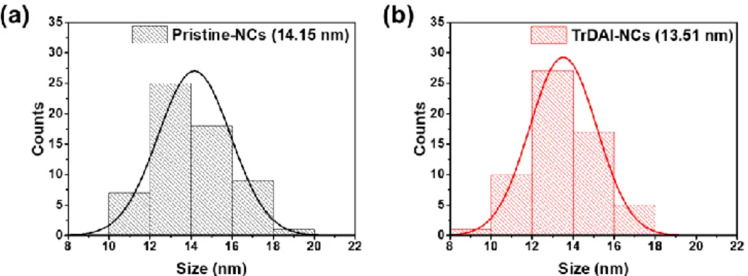
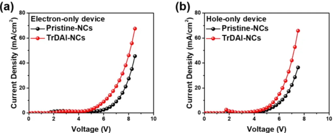
Size distribution of pristine (PR) and surface passivated (SP) PeNCs. a) I–V behavior of pristine (PR) and surface passivated (SP) PeNCs. EL spectra of the driven under different applied voltages of the optimized PeLEDs with anion-exchanged bulk perovskite films, (a).
Introduction
The first LED was born in 1907 by Round.2 The first LEDs were based on SiC crystallite with metal electrodes, forming Schottky diodes, and released the first electroluminescence (EL). The first practical LEDs were based on GaAs semiconductors, which emitted red light, in 1962.3 Based on this discovery, the combination with GaP resulted in green LEDs, and GaAsP-based LEDs were invented achieving red-to-green color by controlling material characteristics.4, 5 In In 1994, the first bright blue LEDs were invented by Nakamura Shuji with GaN semiconductors and the LED era began.6 LEDs based on these crystalline semiconductors achieved very high efficiency and widely used, but have disadvantages of heavy weight and fragile nature.
Halide Perovskite Material Characteristics and Device Physics of Halide Perovskite
- Properties of Halide Perovskites
- Properties of halide perovskite nanocrystals
- Synthesis of halide perovskite nanocrystals,
- Structure of PeLEDs
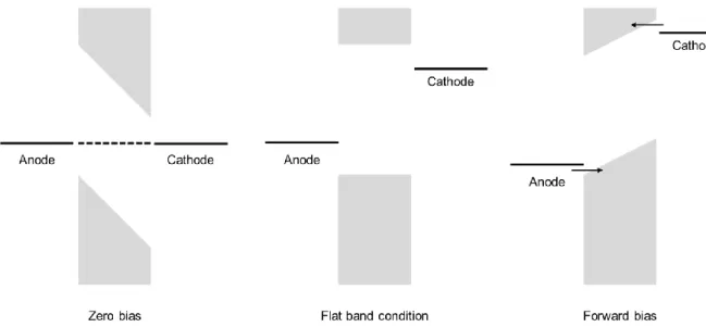
- Operating mechanism of PeLEDs
- Characterizations of PeLEDs
The PeLEDs consist of the emitting layer (EML), anode, cathode, electron transport layer (ETL) and hole transport layer (HTL). Operational spectra stability of the PeLEDs based on the pristine (PR) and surface passivated (SP) PeNCs.
High Performance Perovskite Light-Emitting Diodes with Surface Passivation of
Research background
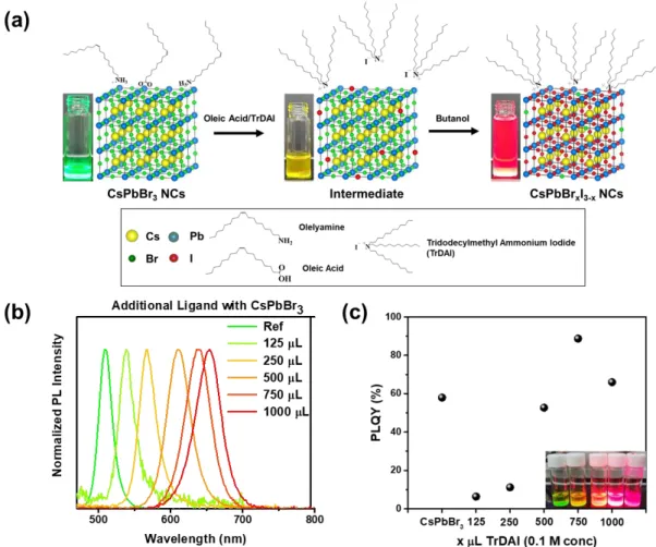
Here, we have demonstrated high-quality CsPbBrxI3-x NCs along with high stability against moisture and superior optical property by a ligand-mediated post-processing (LMPT) method with the halide ion-pair ligand, tridodecylmethyl ammonium iodide (TrDAI). NCs treated with the TrDAI-CsPbBrxI3-x ligand exhibit remarkable colloidal stability against moisture together with low loss of optical properties and a solid perovskite network without structural degradation or phase transition even when stored in air for 7 days at humidity up to 70%.
Experimental details
The samples washed once with butanol and redispersed in toluene were placed on carbon-coated Cu grids from Ted Pella, Inc. dropped. Christmas ) using a graphite monochromator and a scintillation counter.
Result and discussion
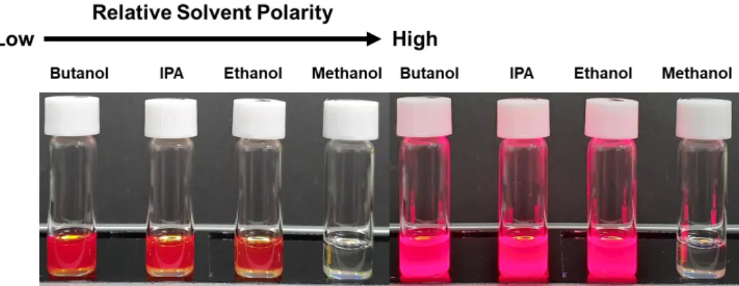
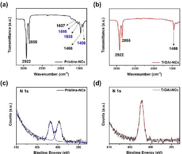
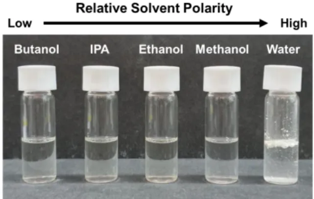
Images of TrDAI-treated CsPbBrxI3-x NCs solution were first washed with different polar solvents and redispersed in toluene. Therefore, we measured FT-IR with pristine- CsPbBrxI3-x NCs and TrDAI ligand treated- CsPbBrxI3-x NCs. Solution stability of CsPbBrxI3-x NCs; (e) PLQYs and (f) Photoluminescence spectra of the as-prepared Pristine and TrDAI-treated CsPbBrxI3-x NCs solution just synthesized and after holding.
The bromine to iodine ratio was checked for correspondence with the as-synthesized pristine-CsPbBrxI3-x and TrDAI ligand-treated CsPbBrxI3-x NCs. Photoluminescence quantum yield of Pristine- and TrDAI- treated NCs CsPbBrxI3-x were first washed with butanol and redissolved in toluene. Optimized PeLED characteristics: (a) Device bandgap energy diagram, (b) electroluminescence, (c) J-V-L, (d) current efficiency, (e) external quantum efficiency, and (f) device luminance decay under a constant bias, 4.1 V with Prishtina- and TrDAI-CsPbBrxI3-x treated NCs as the emissive layer.
As shown in Figure 3.16, we further compared both electron and hole current densities of pristine and TrDAI ligand-treated CsPbBrxI3-x NCs through an electron-hole-only device.
Conclusion
Reversible, Full Color Luminescence by Post-treatment of Perovskite Nanocrystals
Research background
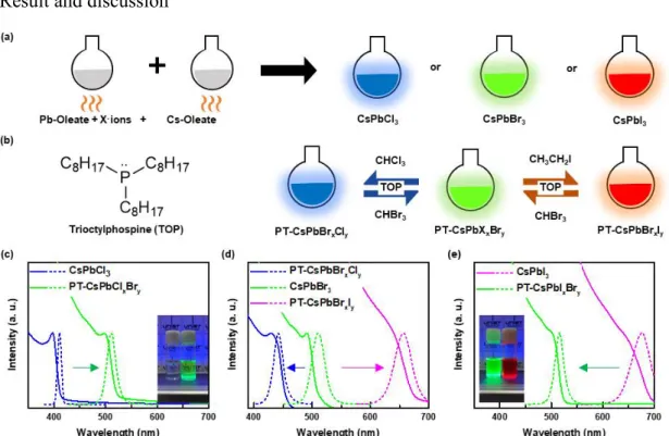
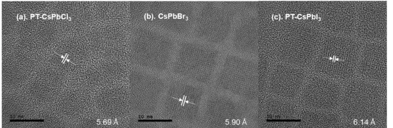
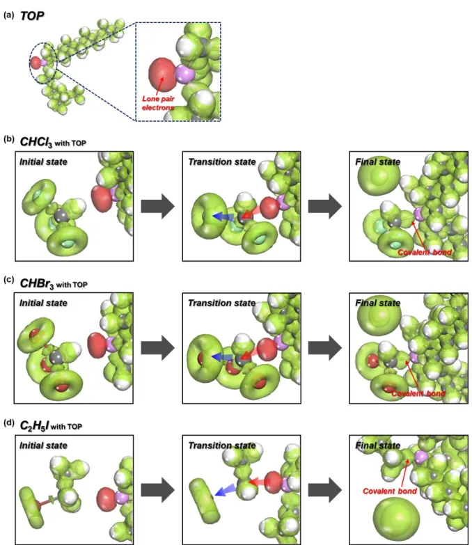
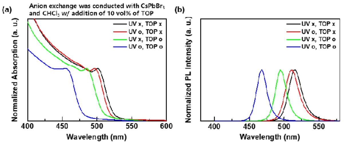
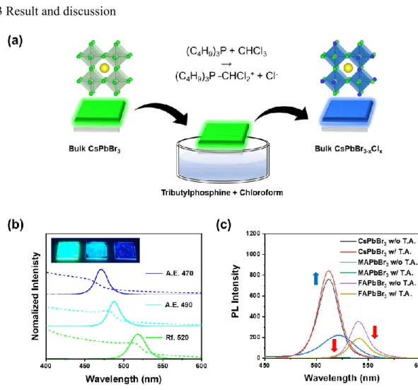
In this work, we have discovered, for the first time, a fully reversible method (CsPbCl3 ⇌ CsPbBr3 ⇌ CsPbI3) after anion exchange treatment for CsPbX3 (X = Cl, Br, I) PeNCs using haloalkane solvents, which is facilitated by the presence of a nucleophile. Haloalkane solvents were used as halogen sources in combination with nucleophilic phosphine ligands to cleave the halogen-carbon bond. Trioctylphosphine (TOP) acted as a strong nucleophile, facilitating an SN2 chemical reaction to produce halide anions75 as well as functioning as an organic ligand.76, 77 Through fine control of posttreatment conditions during anion exchange, we have achieved nanocrystals with adjustable luminescence, which covers the entire visible spectrum from 400 nm ~ 700 nm.
Experimental details
UV-vis absorption spectra were collected on a Cary 5000 (Agilent) and PL spectra were collected on an NF900 instrument (Edinburg) with a xenon lamp as the excitation source. Samples were prepared by spin-coating 80 nm thick gold films on Si substrates with a thin native oxide layer. XPS spectra were collected using a Thermo Fisher Scientific ESCALAB 250XI at a base pressure of 1.0 × 10⁻⁹ Torr with a monochromated Al-Kα X-ray source.
Samples were prepared from 2-fold diluted solutions with toluene and cast onto carbon-coated Cu grids from Ted Pella, Inc. We performed density functional theory (DFT) calculations to investigate the role of TOP molecules in the separation of halogen atoms from haloalkane solvent molecules. The effect of the TOP molecule on the dissociation of the halogen atom was studied by calculating the energy (ΔE) and Gibbs free energy (ΔG) changes of each system.
The type I interaction, where the lone pair on the P atom protrudes (away from octyl chains) to interact with haloalkane molecules (Figure 4.9a), was found to be the most stable configuration due to the favorable interaction energy.
Result and discussion
Note that red dotted arrows indicate the distance between P of TOP and the carbon center of the solvent molecule, while blue dotted arrows correspond to the distance between halogen atoms the carbon center of the solvent molecule. In the case of anion exchange of CsPbBr3 PeNCs using a mixture of CHCl3 and CHBr3, optical properties of the PeNCs exhibited Br dominant features (Figure 4.8), which is consistent with the DFT results shown in Figure 4.6. Blue dotted arrows indicate the distance between halogen atom and carbon center of the solvent molecule, which was originally bonded to the halogen atom.
Note that the red dotted arrows indicate the distance between the P of TOP and the carbon center of the solvent molecule, while the blue one corresponds to the distance between the halogen atom and the carbon center of the solvent molecule. FTIR spectra of supernatant solvent of PT-CsPbBrxCly PeNCs after halide exchange and reference spectra of trihalomethanes. 1H-NMR spectra of the supernatant solvent collected from PT-CsPbBrxCly PeNCs after anion exchange compared to a CHCl2Br reference solution.
Note that red dashed lines indicate the distance between P of TOP and the carbon center of the solvent molecule and blue arrows for that between the halogen atom and the carbon center of the solvent molecule.
Conclusion
Origin of Luminescence Spectra Width in Perovskite Nanocrystal with Surface
Research background
In this work, we sought to find the origin of the narrow emission linewidth of luminescence from blue (@470 ± 2 nm) emitting PeNCs with surface passivation. By comparing the emission line width between pristine PeNCs (PR-PeNCs) and PeNCs with surface passivation (SP-PeNCs), the differences in full width at half maximum (FWHM) of the emission spectra were focused on to find out the origin of the emission linewidth. It was revealed that the narrower luminescence spectra originated from ligand passivation and the improved optoelectronic properties originated from anion passivation.
Experimental details
The precipitated PeNCs were collected by centrifugation (at 12 000 rpm for 15 min) and redispersed in toluene or hexane. Device fabrication proceeded after an adaptation of the method reported by Pan et al.43 Briefly, PEDOT:PSS solutions were spin-coated onto precleaned glass/ITO substrates at 3000 rpm for 40 s, followed by thermal annealing at 150 °C. for 15 minutes under air. After cooling to ambient temperature, the PeNCs were dispersed at 2000 rpm for 60 s in an N2-filled glovebox.
Result and discussion
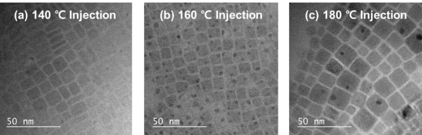
In the hot injection method, the synthesis injection temperature controls the average size of the nanocrystals. TEM images were obtained to confirm the mean size and size distribution of PeNCs (Figure 5.2). Similarly, the tendency of the FWHM appeared to be related to the mean size, but not to the size distribution.
With these data, the average size of the PeNCs appeared to have more effect on the FWHM of PeNCs than the size distribution of PeNCs, regardless of the compositional variation. Thus, nucleophilic ligands with different alkyl chain lengths (tributylphosphine (TBP), trihexylphosphine (THP) and trioctylphosphine (TOP)) were applied to see the difference in the ligand passivation ability on the surface of the PeNCs. The ligand passivation effect of surface passivation reduced the defects on the Pb atoms in PeNCs and narrowed the FWHM of the emission spectra.
From the above results, the quality of the PeLEDs was determined by the surface passivation of PeNCs.
Conclusion
Cs-base Inorganic Bulk Blue Perovskite LEDs with Anion-exchange Method
- Research background
- Experimental details
- Result and discussion
- Conclusion
Uv-vis absorption and photoluminescence spectra of reference (Rf. 520) and anion-exchanged bulk perovskite films (A.E. 470 and A.E. 490 conditions). Reference Tauc plot (Rf. 520) and anion-exchanged bulk perovskite and measured optical band gaps are given. Time-resolved photoluminescence lifetime at detection wavelength 520, 490, and 470 nm of reference (Rf. 520) and anion-exchanged bulk perovskite films deposited on glass/PEDOT:PSS.
Energy dispersive X-ray (EDX) spectroscopy images corresponding to elemental mapping of Cs, Pb, Br and Cl in (a–d) reference (Rf. 520), (e–h) anion-exchanged bulk perovskite films, A.E. The surface images of pristine (Figure 6.14a) and anion-exchanged bulk perovskite films (Figures 6.14b and 6.14c) were obtained from the SEM measurements. UPS spectra (left: secondary electron cutoff region, right: onset region) of reference (Rf. 520) and anion-exchanged bulk perovskite films via dipping method.
Summarized energy level values for anion exchanger bulk perovskite films measured from UPS and Tauc plots.
Summary
Chiba, T.; Hayashi, Y.; Ebe, H.; Hoshi, K.; Sato, J.; Sato, S.; Pu, Y.-J.; Ohisa, S.; Kido, J., Anion-Exchanging Red Perovskite Quantum Dots with Ammonium Iodide Salts for High-Efficiency Light-Emitting Devices. Cho, H.; Kim, Y.-H.; Wolf, C.; Lee, H.-D.; Lee, T.-W., Improving the stability of metal halide perovskite materials and light-emitting diodes. Chen, X., Stabilizing Cesium Lead Halide Perovskite Lattices through Mn(II) Substitution for Air-Stable Light Emitting Diodes.
Zhang, J.; Zhang, L.; Cai, P.; Xue, X.; Wang, M.; Zhang, J.; Tu, G., Enhancing the stability of red perovskite nanocrystals by copper substitution for efficient light emitting diodes. Kwon, D.-H.; Bae, J.-H.; Kim, H.-R.; Kang, S.-W., Efficient generation of excitons in atomically passivated CdSe/ZnS quantum dot light-emitting devices. H.; Wang, J.; Huang, W., Perovskite light emitting diodes based on solution processed self-organized multiple quantum wells.
L.; Yang, X., Trifluoroacetate-induced small-grained CsPbBr3 perovskite films result in efficient and stable light-emitting devices.