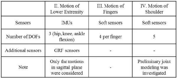
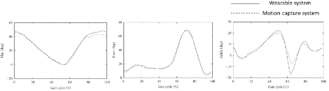
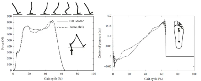
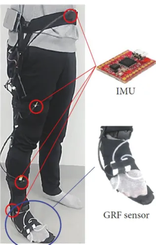
Four IMUs measured hip, knee, and ankle angles by computing the rotation matrix of each sensor. The measured joint angles and GRF by the developed system were compared with a camera-based motion capture system and a fixed force plate. On the other hand, a soft wearable sensor system was developed to measure finger movements, which consisted of soft, stretchable silicon filled with an electro-conductive liquid metal, called eutectic gallium-indium alloy (EGaIn). .
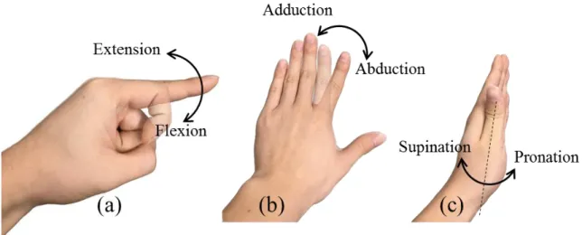
Due to the light weight and highly stretchable properties of silicone, the wearable sensor system allowed natural movements for the user and was able to adapt to different hand sizes. In the proposed system, finger flexion and extension and index finger abduction can be measured. Accuracy in finger motion measurement was verified by the camera-based motion capture system.
The goal of the modeling was to more accurately model the carpometacarpal (CMC) joint of the thumb. The glenohumeral (GH) joint was used to verify the model due to its similar behavior to the CMC joint.
Introduction
In the case of the magnetic position sensor system, joint angles were measured using 3D positions of the fingers [25]. The system, using an optical linear encoder, independently measured flexion/extension angles of the MCP, proximal interphalangeal (PIP), and distal interphalangeal (DIP) joints [ 26 ]. However, it could not measure the abduction/adduction movement due to the structural limitation of the optical linear encoder.
The performance of the proposed sensor system was verified by comparing the joint angles measured by a camera-based motion capture system. In the case of the carpometacarpal (CMC) joint in the thumb and the glenohumeral (GH) joint in the shoulder, they have 3 DOFs: flexion/extension, abduction/adduction, and pronation/supination (or internal/external rotation in the case of the GH joint). To properly attach soft sensors to these joints, kinematic modeling of the joint was required.
The model was verified for the shoulder GH joint and the result was validated by a camera-based motion capture system. In Section IV, a brief explanation of the modeling of a complex joint for joint motion measurement using soft sensors is presented.
![Fig. I.2. Previously developed finger motion measurement systems [22-26, 29]](https://thumb-ap.123doks.com/thumbv2/123dokinfo/10524604.0/13.892.238.665.837.1097/fig-i-previously-developed-finger-motion-measurement-systems.webp)
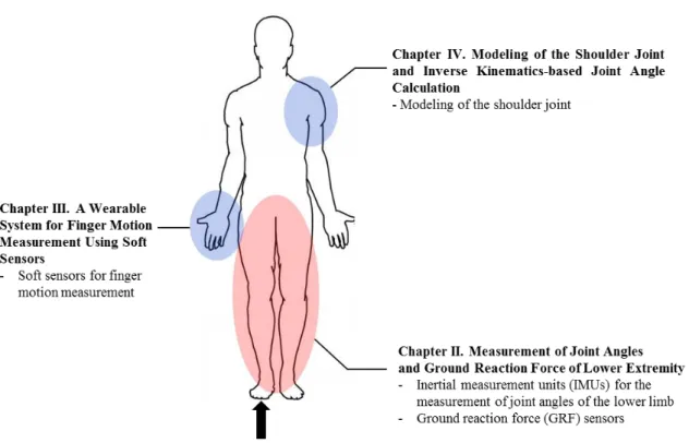
Measurement of Joint Angles and
Ground Reaction Force of Lower Extremity
Introduction
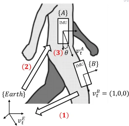
Four IMUs were secured to each segment of the lower limb using cloth straps. To verify the performance of the system, the joint angles measured by IMUs were compared with a camera-based motion capture system. To calculate the joint angle, a unit vector, vtB, was defined with respect to frame {B}, as shown in Fig.
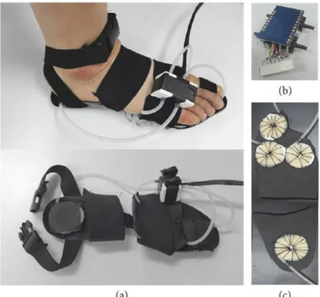
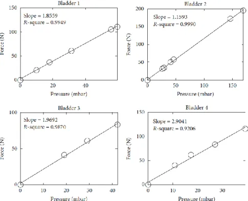
GRF sensor modules: (a) full vision, (b) pressure sensor module, and (c) air bladders attached to the insole. As force was applied to the air bladders, the pressure in the silicone tubes changed. To calculate the actual force applied to the air bladders, it was important to determine the relationship between the applied force and pressure changes.
For the calibration process, the force transducer simultaneously measured the applied force while the air bladders were pressurized. Calibration results of applied force and measured pressure of GRF detection units.
Verification of Joint Angles and GRF Measurement
Conclusion
A Wearable System for Finger Motion Measurement Using Soft Sensors
- Introduction
- Finger Joint Models
- Design of a Soft Sensor System
- Implementation of the Finger Motion Measurement Glove
- Performance verification
- Conclusion
The abduction of finger refers to a movement that moves a finger away from the center of the hand [38]. On the other hand, adduction describes a movement that pulls a finger toward the middle of the hand. The rotation is a movement that depends on FE and AA of the carpometacarpal (CMC) joint, so it can be expressed as a function of FE and AA angles [39].
In the case of the type (3) CMC joint in the thumb, it will be discussed later in Section IV. The movement of the joint can be expressed by a combination of 2 independent movements: FE and AA. The distance indicated L and radius of gyration, r, was determined by the attachment position of the sensor.
The joint angle was calculated using the same procedure as explained for the FE joint angle of type 1 joint. The other one with one microchannel was attached between the 2 sensors to measure the AA pointer. Two sensing units attached to the fingers were stretched by bending the fingers.
As described in III.3, the width and height of the microchannel determine the resistance change for the given strain. The length change of the sensing unit can be calculated as Lr, where r is a radius of the joint surface (Fig. III.4.2). The performance of the proposed sensor system was validated by comparing the joint angles measured by a camera-based motion capture system [44].
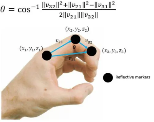
The joint angles were calculated using a simple trigonometric relationship based on the position of the markers. For example, in the case of the PIP joint, the joint angle was calculated from the positions of the reflective markers as shown in Fig. The rapid change of the joint angle caused the larger RMS error due to the hysteresis of the elastomer sensor body.
Schematic diagram of the center with reflective markings for measuring the PIP joint angle. Due to the superior elasticity of the silicone case, it also allowed natural movement of the fingers.
Modeling of the Shoulder Joint and Inverse Kinematics-based
Joint Angle Calculation
- Introduction
- Modeling of Human Joints
- Shoulder Motion Modeling
- Conclusion
- Conclusions
Although the soft sensor system measured the angles of the 2-DOF finger joints, there was a problem for a multi-DOF joint, such as the CMC joint of the thumb, the GH joint of the shoulder, and the hip joint. For proper connection of soft sensors and measurement of joint angles, complex joint modeling should be investigated. Previously developed soft sensor systems measured finger joint angles and the angles were compared with a camera-based motion capture system.
The data obtained with the motion capture system were processed to calculate the reference joint angles. Through the processing, there may be some errors due to the miscalculation of the reference assembly angles. Previously, the reference joint angles were calculated by processing the raw position data of reflective markers obtained by a camera-based motion capture system.
The positions of reflective markers were used for the construction of rotation axes and relative position vector to validate the joint angles. In the case of 2 DOFs joint, for example MCP joint of fingers, it is more complex to define joint angles. To validate the algorithm, forward kinematics were solved by multiplying rotation matrices obtained by joint angles to initial position.
For a given initial position vector, 𝑃0, the position of the end effector can be estimated by multiplying the rotation matrices constructed by joint angles. If the estimated position is equal to the actual position, it can be said that the algorithm has successfully calculated the joint angles. To validate the model, the forward kinematics were solved using the joint angles calculated by an inverse kinematics-based algorithm.
Then solving forward kinematics can prove that the joint angles were calculated successfully by inverse kinematics. The wearable system, using IMUs and GRF sensors, measured the lower extremity joint angles and vertical GRF. To verify the performance of the system, the measured joint angles were compared with the camera-based motion capture system.
The algorithm calculated joint angles using inverse kinematics and it was validated by comparing the positions of end effectors. It was validated that the algorithm and model successfully measured the joint angles and the position of the end effector.
Bae, “Estimation of individual lower limb muscle forces during walking using a wearable sensor system.” Journal of Sensors, 2017. McMillian, et al., “Inertial sensor-based knee flexion/extension angle estimation,” Journal of Biomechanics, vol. Kim, “A wearable sensor system including an optical 3-axis GRF sensor for joint torque estimation in real-time gait analysis,” in Proceedings of the IEEE/ASME International Conference on Advanced Intelligent Mechatronics (AIM ’14), p.
Redfern, “Measurements of wrist and finger postures: a comparison of goniometric and motion capture techniques,” Journal of Applied Biomechanics, vol. Yu, “Feasibility of using a video-based motion analysis system to measure thumb kinematics,” Journal of Biomechanics , vol. Nishiyama and K. Watanabe, “Hetero-core fiber optic nerve-embedded wearable sensor gloves for unrestricted motion capture,” IEEE Trans.
Mitobe, et al., “Development of a motion capture system for a hand using a magnetic three-dimensional position sensor,” in Pro. Park, “Wearable soft artificial skin for hand gesture detection with embedded microfluidic strain sensing,” in Proceedings of the IEEE International Conference on Robotics and Automation (ICRA'15), pp. Tomizuka, “A mobile gait monitoring system for abnormal gait diagnosis and rehabilitation: a pilot study for patients with Parkinson's disease,” Journal of Biomechanical Engineering , vol.
Tomizuka, “A remote monitoring system for gait rehabilitation with an inertial measurement unit and a shoe-shaped ground reaction force sensor,” Mechatronics , vol. Ning and M.Han, “Wearable Gait Analysis System for Ambulatory Kinematics and Kinetics Measurement,” in Proceedings of the 13th IEEE SENSORS Conference (SENSORS '14), p. ISB Recommendation on Definitions of Common Coordinate Systems of Different Joints for Reporting Human Joint Motion - II. part: shoulder, elbow, wrist, and hand.” Journal of Biomechanics, vol.
Buss, "Introduction to inverse kinematics with Jacobian transpose, pseudo-inverse, and damped least-squares methods." IEEE Journal of Robotics and Automation, 2004. Bae, “Development of a Wearable Soft Sensor System for Measuring Finger Movements,” in Proceedings of International Conference on Control, Automation and Systems (ICCAS), pp. BAE, "Real-time Estimation of Individual Muscle Forces of the Lower Limb Using Wearable Sensors," in Proceedings of IEEE/ASME International Conference on Advanced Intelligent Mechatronics (AIM), pp.
Acknowledgments