Surface corrosion of neutron absorbers before and after accelerated corrosion tests. a) Surface corrosion of 4.33 year irradiated neutron absorber after the accelerated one. Oxide film formation on the surface of the neutron absorber before the corrosion tests:.
INTRODUCTION
Motivation
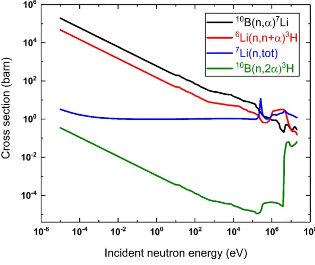
The radiation damage produced by the energetic He and Li ions in the B4C pellet was estimated to be ~380 times higher than that of fast neutrons [22], [23]. The radiation damage from 10B(n, α)7Li reactions has been estimated to be 1-2 displacements per atom (dpa) for 60 years of storage [24], which may be a significant underestimate.
Objectives
The Al-B4C MMC radiation testing program, however, did not account for radiation damage from 10B(n, α)7Li reactions by using a special Al-B4C vessel to reduce thermal neutron exposure of the absorbers during irradiation tests. It appears that a 40-year lifetime was provided only considering radiation damage from gamma/fast neutron irradiation and corrosion without the effects of induced radiation damage.
BACKGROUND
Spent nuclear fuel pool
- Spent nuclear fuel
- Storage expansion and regulation
Increasing SFP storage capacity has received significant attention in recent years as the establishment of permanent disposal facilities has been continuously postponed in most nuclear power countries. The use of neutron-absorbing panels reduces the center-to-center spacing of SNF structures and maximizes the pool's storage capacity.
![Figure 2-1. Cross-section view of PWR core and spent nuclear fuel pool. Reproduced with permission from [32].](https://thumb-ap.123doks.com/thumbv2/123dokinfo/10497461.0/24.892.112.773.125.709/figure-cross-section-view-spent-nuclear-reproduced-permission.webp)
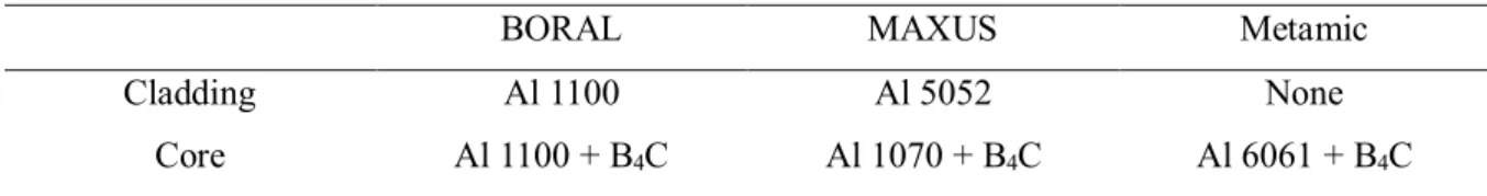
Neutron absorber
- Al-B 4 C neutron absorber
- Surveillance coupons
- In-service degradation
- Research activities on the degradation of neutron absorbers
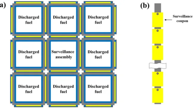
Neutron absorber monitoring coupons are usually attached to a monitoring assembly and installed in an empty storage cell as shown in Figure 2-2. The surveillance assembly is surrounded by recently discharged fuel units to accelerate the rate at which the coupons accumulate radiation damage from the SNF [54]. Since the water in the flux trap region is used to thermalize the neutrons, making the neutron absorber more effective, the bubble can increase the reactivity of the pool [54].
EXPERIMENTAL
- Surveillance coupons
- Microstructure evolution
- Accelerated corrosion tests
- Helium ion irradiation
- Sample preparation
- Helium ion irradiation
- Electrochemical tests
- Performance evaluation
- Thermal neutron transmission rate
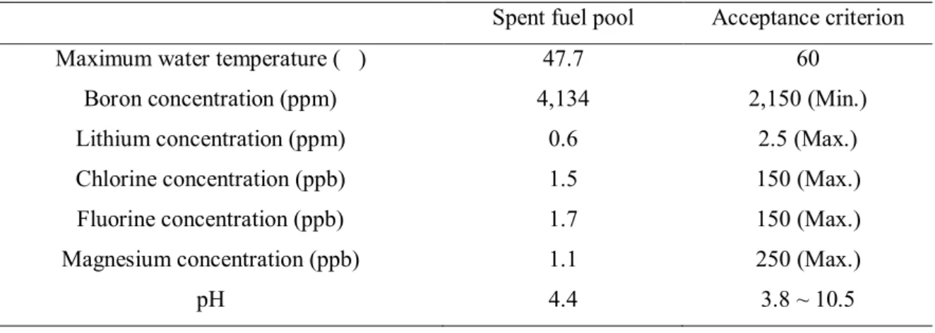
The chemistry of the water in the coolant was determined based on measured data from the SFP, in which control coupons were collected. SFP water chemistry is shown in Table 3-1 with acceptance criteria provided by KHNP. The loop flow rate was maintained at 25.2 L/h, which was calculated from the normal SFP circulation rate.
The coolant was periodically drained from the tank and analyzed by an inductively coupled plasma mass spectrometer (ICP-MS, ELAN DRC II, PerkinElmer) to monitor the ion concentration change during the accelerated corrosion tests. The matrix material of the absorber, Al 6061 sheet (Alfa Aesar), was used to mimic the radiation damage caused by 10B(n, α)7Li reactions observed in the neutron absorbers, as it was difficult to as- to obtain fabricated Al-B4C MMC. . To monitor any changes in neutron flux due to power fluctuations, a BF3neutron detector measured the power count rate (Cpower) in front of the sample position.
Two separate BF3 neutron detection systems were used to measure the raw count rates (Craw) from the absorber and the background.
RESULTS
Comprehensive characterization of neutron absorbers
- Surface corrosion
- Radiation-damaged microstructure
- Porosification and 10 B depletion
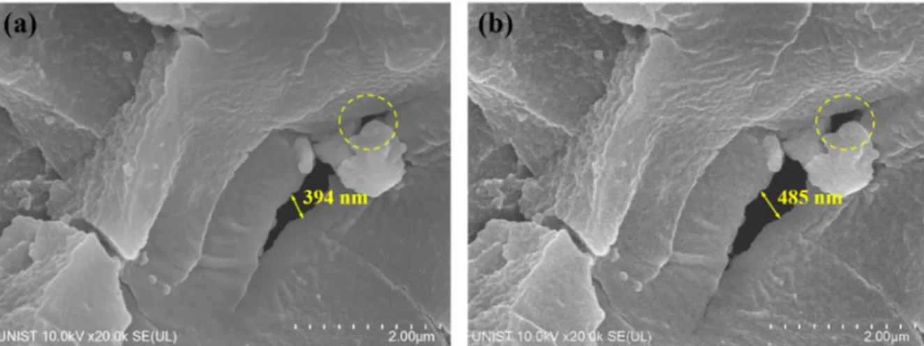
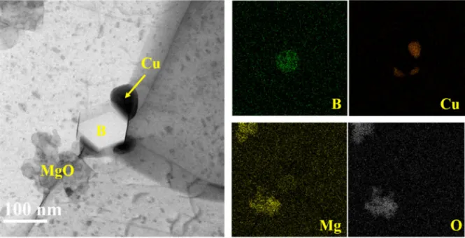
BF TEM image of elemental analysis of precipitates in the aluminum matrix of 2.75 year irradiated neutron absorber. To reveal the composition of observed bubbles, STEM-EELS was performed on a ~60 nmD bubble and the Al matrix of the 8.25 yr irradiated absorber. Microcracked boron carbide particles observed in (a) 2.75 year, (b) 4.33 year, and (c) 8.25 year irradiated neutron absorber and (d) pits on the boron carbide particle of 4.33 year irradiated neutron absorber.
Two EELS measurement points and one stroke due to an electron beam damage in 8.25 years irradiated neutron absorber. Low EELS spectra of aluminum matrix and the observed bubble in 8.25 year irradiated neutron absorber with K-edge peaks of hydrogen and helium. The neutron transmission rate of the neutron absorber was compared to the coupon with the least exposed period (2.75 years of irradiated absorber) as it was difficult to obtain as fabricated coupons.
It appears that the longer 47-month storage period for the irradiated neutron absorber of 8.25 years had resulted in an additional reduction in the 10B surface density of ∼3.1%.
Accelerated corrosion tests of the neutron absorbers
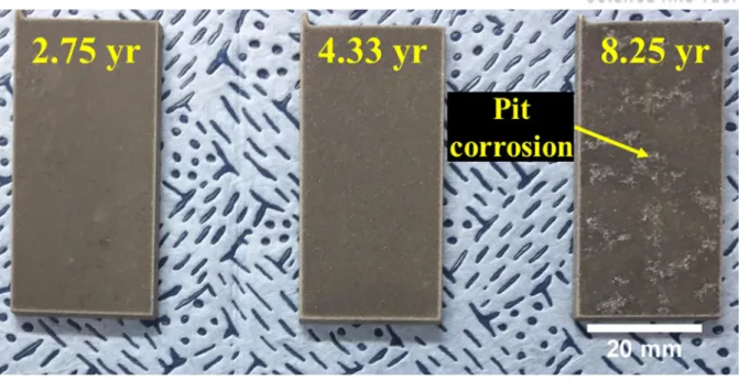
- Weight gains and surface corrosion
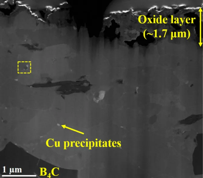
- Double oxide layer formation
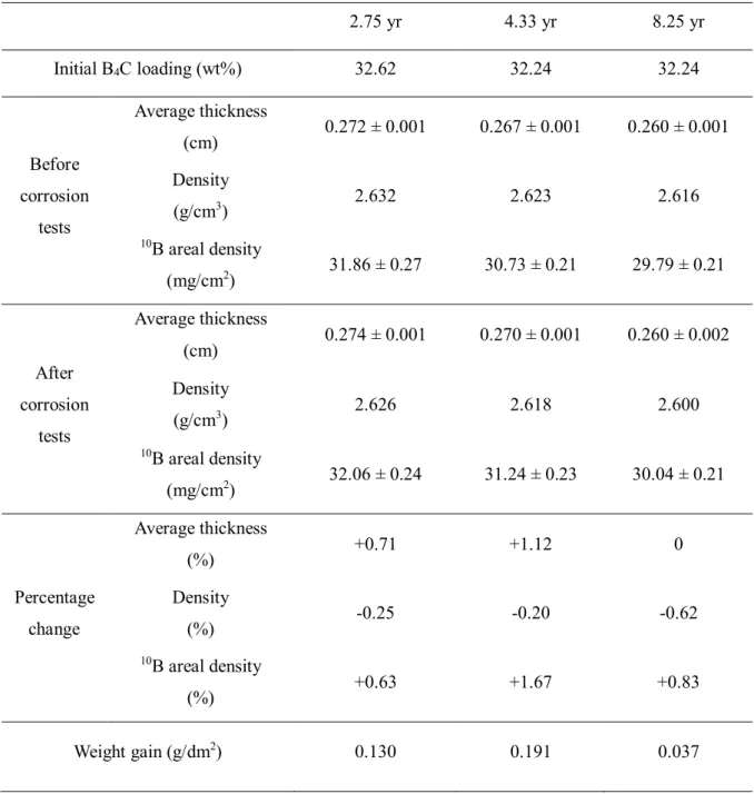
- Electrochemical properties and 10 B areal density
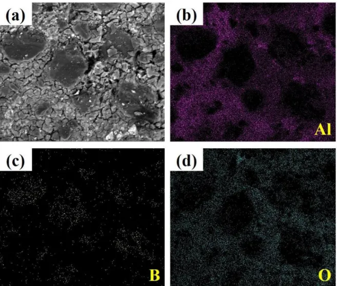
Surface corrosion of neutron absorbers before the corrosion tests: (a) 2.75 years, (b) 4.33 years and (c) 8.25 years irradiated absorber, and surface corrosion of neutron absorbers after the corrosion tests: a) Surface corrosion of a 4.33 years long irradiated neutron absorber after the accelerated corrosion tests and elemental distributions of (b) aluminum, (c) boron, and (d) oxygen. The surfaces of neutron absorbers were characterized using TEM prior to corrosion testing to investigate the evolution of the microstructure during the six-month corrosion tests. A porous surface with MgO precipitates was found in all neutron absorbers, and numerous bubbles were observed in the irradiated 4.33 and 8.25 year absorbers, as shown in Figure 4.17(b) and (c).
On the contrary, no dense inner oxide film and MgO precipitates were found in irradiated absorbers of 4.33 and 8.25 years, as shown in Figure 4.17(e) and (f). The duplex oxide film on both 4.33 year and 8.25 year irradiated absorbers contains a porous inner layer consisting of Al(OH)3 and an amorphous outer layer after the corrosion tests. However, no significant change in the surface density of 10B was observed in all neutron absorbers after the corrosion tests (Figure 4-20).
10B Surface density of the Al-B4C metal matrix composites before and after the corrosion tests.
Helium ion-beam irradiation
- Aluminum 6061 alloys
- As-fabricated neutron absorbers
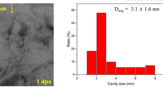
Ion irradiation in Al 6061 and B4C particles. a) TEM images of 6061 aluminum alloys irradiated with He ion 200 keV to 0.1 dpa (b) Black spot formation in the peak concentration region. a) TEM images of 6061 aluminum alloys irradiated with He ion 200 keV to 1 dpa (b) Cavity formation in the peak concentration region. a) TEM images of 6061 aluminum alloys irradiated with 200 keV He ion up to 10 dpa (b) Cavity formation in the peak concentration region.
DISCUSSION
Irradiation accelerated degradation
- Neutron absorption reactions
- Discrepancies between the operating experience and qualification tests
- Microstructures comparison between Al matrix and B 4 C particles
- Estimation of 10 B depletion
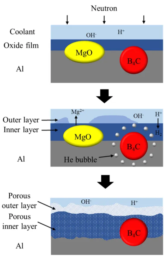
(4) Accumulated gaseous atoms, increased vacancy concentration, and continued ion bombardment near the B4C particles work together to form numerous radiation-induced voids and bubbles. In the case of the above formation mechanism, B4C particles located on the absorber surface are probably surrounded by the nano-porous region that serves as a fast diffusion path for oxygen ions. This radiation-assisted corrosion may cause loss of B4C particles, perhaps due to weakened mechanical properties and slightly increased volume of the oxidized porous area around B4C particles.
These cracks were frequently observed along the grain boundaries of B4C particles due to the preferential trapping of helium gas at the grain boundary [79] and the presence of free graphite in non-stoichiometric B4C [82], [83]. The surface degradation of B4C particles may lead to the potential risk of minor 10B loss; however, the particle loss will be largely limited on the absorber surface, thus also a limited impact on the pool criticality. Even in the case where large bubbles were somehow successfully grown in B4C by overcoming the higher shear modulus, accumulated shear stress due to the bubble formation would eventually cause brittle fracture of the particle and lead to the He gas release; thus less detectable He bubbles remnant in microcracked B4C particles.
In this regard, the lithium ions could be relatively homogeneously distributed in B4C particles and Al matrix at low concentrations, and therefore difficult to detect using EDS and EELS.
Long-term performance evaluation
- Acceleration factor
- Corrosion behavior
Since adding reinforcing particles could interrupt the formation of aluminum oxide films on the surface, the discontinuous oxide film could increase the corrosion susceptibility. A dense oxide film containing Mg precipitates was observed only from the surface of a 2.75 year absorber, as shown in Figure 4-17(d). This result is probably because the dissolution of Mg precipitates decreased the corrosion resistance of the Al matrix and formed a porous oxide film on the surface of the 4.33 and 8.25 year absorber during the corrosion tests.
The outer layer of the alumina film is known to be hydrolyzed to form hydrated oxides such as bayerite (Al(OH)3/Al2O3·3H2O) formed around 70 °C and boehmite formed above 100 °C [98 ]. This result was probably due to the formation of a dense internal oxide film on the 2.75-year absorber, which protects the metal surface from corrosion. The highly damaged oxide film with numerous defects and gas bubbles on the surface (Figure 4-17(e) and (f)) could be attributed to the formation of an open channel that causes.
Oxide films thicken with the dissolution of Mg precipitates, and aluminum corrosion reactions produce hydrogen gas; and (3) gas bubbles filled with hydrogen and helium eventually fuse into a porous oxide film, and the duplex oxide layer is formed on the surface of neutron absorbers.
Experimental estimation on radiation damage
- Radiation damage accumulation in the neutron absorber
- Cavity formation in irradiated neutron absorber
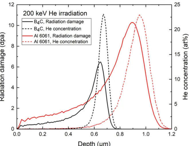
It appears that the size of helium bubbles is determined by helium concentration rather than radiation damage, which is consistent with previous studies. The average size of voids on these sites is larger than that of bubbles on Al alloys. Inhibited void growth in BORAL, probably due to the proximity to the grain boundary, resulted in a smaller average size of voids in BORAL than that in MAXUS.
A band of small helium bubbles was found in the area of highest helium concentration in the B4C particles, as shown in Figure 5-12. The size of helium bubbles in B4C particles was much smaller than in Al alloys. Morphology and size distribution of helium bubbles at a depth of 0.8 μm in Al 6061 irradiated to 1 dpa peak.
Morphology and size distribution of helium bubbles at depths of 0.8 μm in Al 6061 irradiated to 10 peak dpa.
CONCLUSIONS
Nanoscale characterization of neutron absorber
Additional accelerated corrosion tests
Estimation of radiation damage accumulated in the neutron absorber
Evaluation of Long-Term Performance of BORAL® in Spent Fuel Pools”, Transactions of the American Nuclear Society, Washington, DC, USA, October 29 – November 2, 2017, vol. Metwally, “Sensitivity studies in safety analysis of spent fuel pool criticality for APR-1400 nuclear power plants,” Nucl. 55] Nuclear Energy Institute, “Guidance for Monitoring of Fixed Neutron Absorbers in Spent Fuel Pools”, Washington, DC, USA, 2016.
Harris, “Accelerated Corrosion Tests to Assess Long-Term Performance of BORAL® in Spent Fuel Pools,” in Proceedings of the 19th International Symposium on Packaging and Transport of Radioactive Materials, PATRAM 2019, New Orleans, LA, USA, August 4-9, 2019. 66] Electric Power Research Institute, “Evaluation of the Effect of Bubbling and Porous Neutron Absorber Material on Spent Fuel Pool Reactivity,” Palo Alto, CA, USA. 67] Electric Power Research Institute, "BADGER, A Probe for Nondestructive Testing of Boron-10 Absorber Residual Density in Spent Fuel Storage Racks: Development and Demonstration,".
Harris, "Oversigt over Zion Comparative Analysis Project for Assessment of BORAL®Neutron Absorber Material Performance and Monitoring in Spent Fuel Pools," i Proceedings of the ANS Conference: 2015 International Conference on.
![Figure 2-3. The surveillance coupons of Boraflex harvested from a spent fuel pool [14].](https://thumb-ap.123doks.com/thumbv2/123dokinfo/10497461.0/37.892.112.788.127.577/figure-surveillance-coupons-boraflex-harvested-spent-fuel-pool.webp)
![Figure 2-6. (a) BADGER in a spent fuel pool [73] (b) axial view of BADGER [13].](https://thumb-ap.123doks.com/thumbv2/123dokinfo/10497461.0/42.892.136.779.138.466/figure-badger-spent-fuel-pool-axial-view-badger.webp)
![Figure 3-3. Gaseous ion beam accelerator used for 200 keV He ion irradiation [77].](https://thumb-ap.123doks.com/thumbv2/123dokinfo/10497461.0/50.892.118.778.129.401/figure-gaseous-ion-beam-accelerator-used-200-irradiation.webp)