This very useful book is intended for a first course in robot vision and covers the design and implementation of intelligent robots. This textbook is the result of many years of research, software development, teaching and learning.
Introduction to Intelligent Robotics
Introduction
History of Robot
Al-Jazari, a Muslim inventor during the Artuqid dynasty, designed and built a number of automatic machines, including kitchen appliances, musical automata powered by water, and the first programmable humanoid robot in 1206. The first service robot from Indonesia named Srikandi III with the stereo vision system and multiple obstacle avoidance capability developed at ITS Surabay.
![Figure 1.1 R.U.R by Czech Writer [2].](https://thumb-ap.123doks.com/thumbv2/azdokorg/8356928.79779/14.680.86.619.193.482/figure-r-u-r-by-czech-writer.webp)
Types of Robot
Whether it's rolling on wheels, walking, or moving with thrusters, a robot must be able to move. How your robot gets its power will depend on what your robot needs to do.
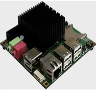
Embedded Systems for Robot
Ackermaan steering, where the movement of the robot is controlled by the 2 front wheels and 2 rear wheels. Omni-directional drives, where the robot's movement can be controlled 3 or 4 wheel system that can rotate in any direction, so that the robot's orientation is maintained.
Robot Vision
Intelligent telepresence robot experiments were tested by navigating the robot to a staff person and avoiding obstacles in the office. The robot was controlled with an integrated web application (ASP.Net and WebRTC) from Master Control.
![Figure 1.12 Perception model for a stereo vision [11].](https://thumb-ap.123doks.com/thumbv2/azdokorg/8356928.79779/26.680.100.616.207.341/figure-perception-model-for-a-stereo-vision.webp)
Exercises
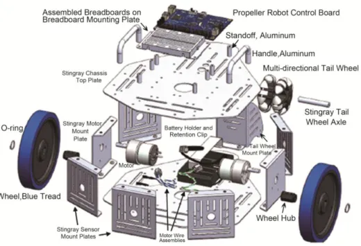
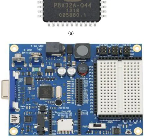
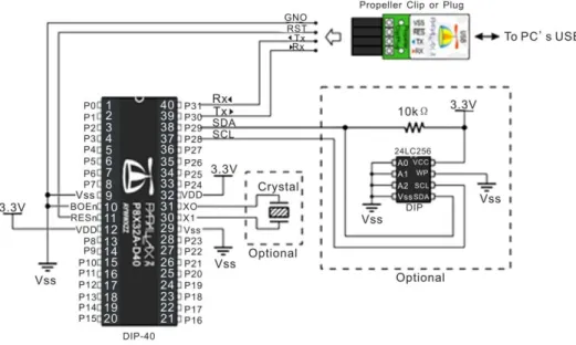
Propeller Microcontroller
Introduction of Propeller Chip
The Propeller chip is a multi-core microcontroller that can be programmed in both high-level languages (Spin™ and C) as well as low-level languages (Propeller assembly). Propeller 2 has easy encoding for video (VGA, composite and component for HD), human interface devices, sensors and output devices.
Programming the Propeller
Use LEDs, resistors and pluggable wires to create the circuit shown in the schematic below on the breadboard. P0 and P1 are taken from the top row (marked W) and are indicated on silkscreen on the control board.
Basic Programming Robot
Programming the robot using microcontroller is the basic principle of controlling the robot, where the orientation of the microcontroller is to control the application of an information system based on the input received, and processed by a microcontroller, and the action performed on the output corresponding to predetermined program.
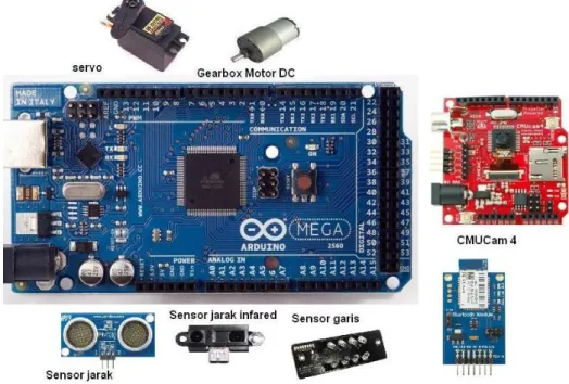
Robot’s Actuators
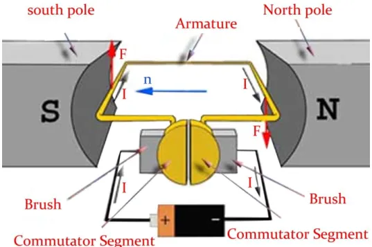
DC Motor
To understand the working principle of DC motor, it is important that we have a clear understanding of Fleming's left hand rule to determine the direction of the force acting on the armature conductors of the dc motor. Fleming's left hand rule states that if we extend the index finger, middle finger and thumb of the left hand so that the current conductor is placed in a magnetic field (represented by the index finger) is perpendicular to the direction of current. (represented by the middle finger), then the conductor experiences a force in a direction (represented by the thumb) mutually perpendicular to both the direction of the field and the current in the conductor.
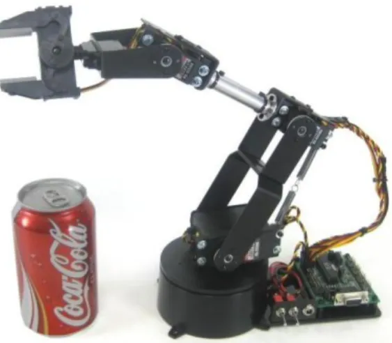
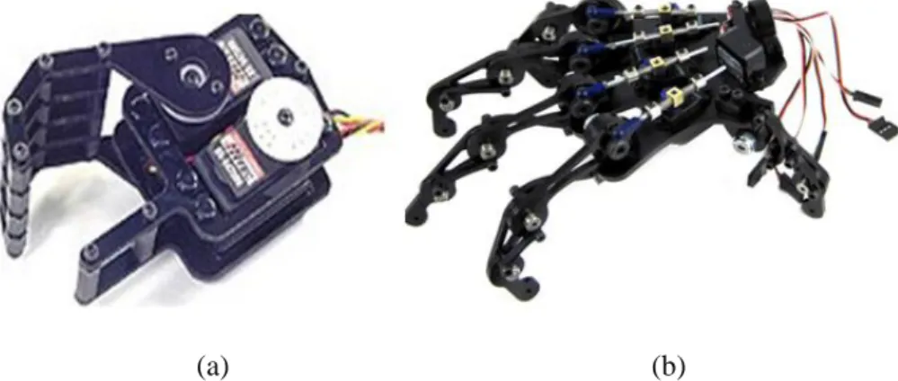
Servo Motor
The author recommends to conduct experiments and make the system-based visual servo robotic arm that can pick up an object using a stereo camera based on the robotic arm. Robot arm is best used Dagu 6 degrees of freedom and AX18FCM5 intelligent robot arm using CM-5 controller, full position, speed, load, voltage and temperature feedback, full position control (300 degrees), uses AX-servo 18F and is compatible with MATLAB and other common microcontroller systems.
Programming Motors of Robot
Sensors for Intelligent Robot
Here is an example that uses a PING))) as an avoider robot that can only detect the obstacle in front of the robot with 1 PING))). LCD.init(LCD_Pin, LCD_Baud, LCD_Lines) ' Initialize LCD Object LCD.cursor(0) ' Turn off cursor.
![Figure 3.6 The basic principle of ultrasonic distance sensor [2].](https://thumb-ap.123doks.com/thumbv2/azdokorg/8356928.79779/54.680.105.597.115.295/figure-basic-principle-ultrasonic-distance-sensor.webp)
PID Controller for the Robot
3.1) In Propeller microcontroller we can use Propeller Object Exchange called A quadrature encoder and PID controller driver running in a gear. It provides full support for getting the quadrature encoder's current position and position delta in ticks and setting the quadrature encoder's current speed in ticks per second through PID control through a standard DC motor.
Serial Communication with Robot
Private Sub btnConnect_Click(ByVal sender As System.Object, ByVal e As System.EventArgs) Obravnava btnConnect.Click. Private Sub btnDisconnect_Click(ByVal sender As System.Object, ByVal e As System.EventArgs) Obravnava btnDisconnect.Click.
![Figure 4.1 Serial communication format[1].](https://thumb-ap.123doks.com/thumbv2/azdokorg/8356928.79779/76.680.98.606.544.709/figure-serial-communication-format.webp)
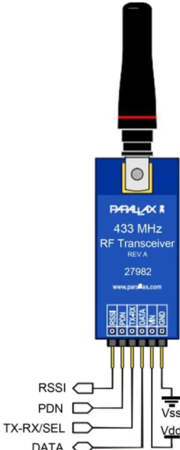
Wireless Communication for Robot
The 802.15.4 XBee modules offer two friendly modes of communication – a simple serial method of transmit/receive or a framed mode that offers advanced features. XBee 802.15.4 modules are cross-compatible with other 802.15.4 XBee modules, regardless of antenna type or power rating.
Mechanics of Robots
Introduction of Gears
If you wanted a simple gear ratio, say 2 to 1, you would use two gears, one twice as big as the other. If the diameter of one gear is 3 times the diameter of the other gear, you will get a gear ratio of 3/1 (or 1/3).
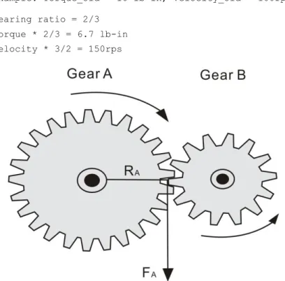
Types of Gears
To calculate, multiply this number by your Velocity_New and Torque_New to get the true output speed and torque [3][4]. This is good for say if you have a robotic arm holding something heavy and you don't want to waste torque holding power.
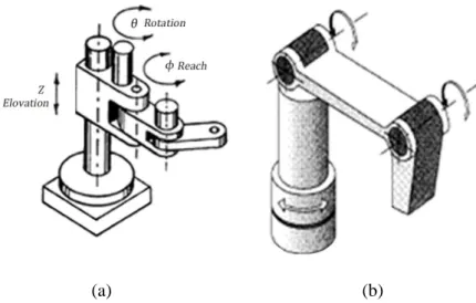
Arm Geometries
An example of a manipulator for industry is the KUKA KR 5 bow, which rounds off the range of KUKA robots at the lower end. Regardless of whether it is mounted on the floor or, conversely, overhead, the KR 5 arc always performs its tasks reliably.
Kinematics of Robot
Introduction to OpenCV
Computer vision is the most important technology in the future in the development of intelligent robot. As a scientific discipline, computer vision is concerned with the theory behind artificial systems that extract information from images.
Introduction of OpenCV
While it is true that robotic systems exist (including many successful industrial robots) that lack sensory equipment (or have very limited sensors), they are often very fragile systems. It is therefore not surprising that the study of robot vision and intelligent robotics go hand in hand.
Digital Image Processing
According to this comparison, red contributed 33%, green contributed 59%, which is greater in all three colors, and blue contributed 11%.

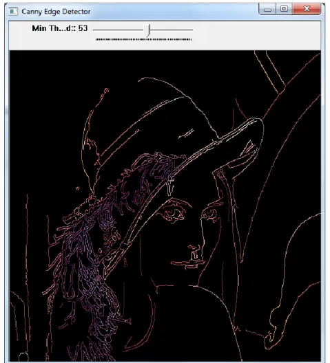
Edge Detection
Good localization: The distance between detected edge pixels and real edge pixels should be minimized.
Optical Flow
Programming OpenCV
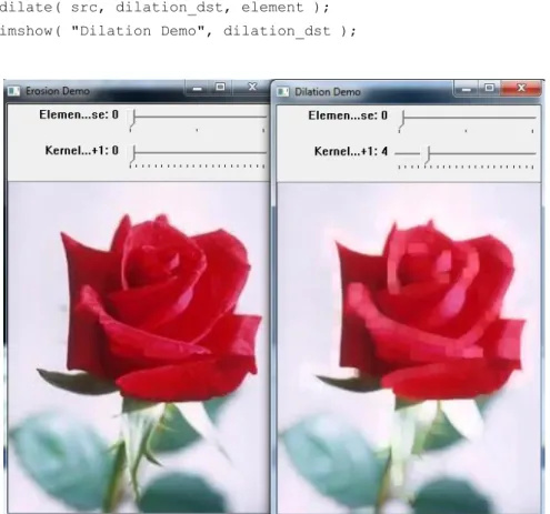
Morphological Filtering
Develop a program to track an object using MeanShift() and CamShift(). in terms of basic erosion and dilation operations. Closing is defined as image propagation erosion and opening as image erosion propagation.
Camshift for Tracking Object
Extracting the Component’s Contours for Calculating Number of Objects
Introduction of Contours
So for this research, we propose a simple mechanism to calculate the objects in an image by processing the contour and shape description of an image using connected component. Many OpenCV functions are available when it comes to shape descriptor and offer a simple function which extracts the contours of the connected components in an image using the cv::findContours function.
Counting Objects
Face Recognition Systems
Unfortunately, developing a computational model for face recognition is quite difficult, since faces are complex, important visual stimuli, and multidimensional. Modeling of facial images can be based on a statistical model, such as principal component analysis (PCA) and linear discriminant analysis (LDA), as well as physical modeling based on the assumption of some surface reflectance properties, such as a Lambert surface.
Face Recognition in OpenCV
Face recognition based on the geometric features of a face is probably the most intuitive approach to face recognition. It is still an open research question what is the best way to preserve spatial information when applying a local feature extraction, because spatial information is potentially useful information.
Haar Cascade Classifier
The linear discriminant analysis performs a class-specific dimensionality reduction and was invented by the great statistician Sir R. You must tell the classifier the directory to use, such as haircascade_frontalface_default.xml.
![Figure 9.1 Haar-like input feature that are used by classifiers [2].](https://thumb-ap.123doks.com/thumbv2/azdokorg/8356928.79779/146.680.111.601.112.436/figure-haar-like-input-feature-that-used-classifiers.webp)
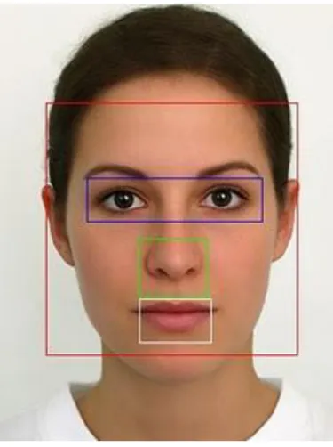
Face Features Detector
In this research, we construct images under different illumination conditions by generating a random value for the illumination level for the ITS face database. Each set of the ITS face database consists of 3 poses (front, left, right) and variable with illumination [13].
Rapid Object Detection with a Cascade of Boosted Classifiers Based on Haar-like Features
If 1, then a simple stub classifier is used, if 2 and more, then CART classifier with number_of_splits internal (split) nodes is used. 3] Chatib, O., Real-Time Obstacle Avoidance for Manipulators and Mobile Robots., The International Journal of Robotics Research, 1986; Vol.
![Figure 9.6 Face and Gender Recognition Systems (improved from [21]).](https://thumb-ap.123doks.com/thumbv2/azdokorg/8356928.79779/169.680.108.589.457.841/figure-face-gender-recognition-systems-improved.webp)
Intelligent Humanoid Robot
Color object detection is used to detect the ball, while a PID controller is used to control the pan tilt camera system. We also modify the CM-510 robot controller so that it can effectively communicate using the main controller.
Humanoid Robot
One of the performance factors of a humanoid soccer ball is that it relies heavily on its tracking ball and ability to move. The complexity of human-like football makes it necessary to play with the development of complex behaviors, for example situations of coordination or different division of roles during the match.
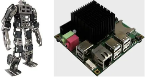
The Architecture of the Humanoid Robot
The firmware of the robot to control the servos was modified from the original one called Robotis Firmware due to the limitation for sending a movement command through a serial interface based on Peter Lanius works published in Google Code (Lanius, 2013). The robot's control starts with initialization routines of CM-510 controller and then moves to Wait for Start Button state.
Ball Distance Estimation and Tracking Algorithm
We use a PID controller to calculate an error value as the difference between a measured (input) and a desired setpoint to control high-speed HS-85 servos.
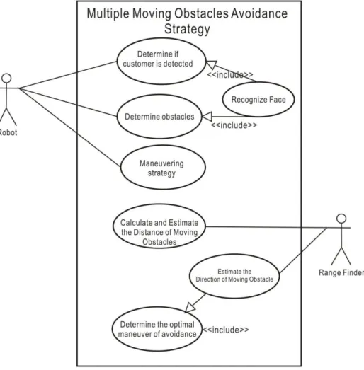
A Framework of Multiple Moving Obstacles Avoidance Strategy
Direction estimation of obstacles will be used to determine the optimal maneuver of the robot to avoid these obstacles. When a ball is in front of the robot and has been detected, the robot tries to track the ball and if the ball is in the closest position with the robot, the robot will kick it as shown in Figure 10.8.
Object Detection Using Keypoint and Feature Matching
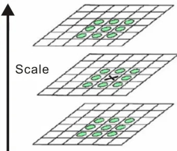
Difference of Gaussian is obtained as the difference of Gaussian blur of an image with two different σ, let it be σ and kσ. Key points are detected using scale-space extrema in difference-of-Gaussian function D and efficient to compute.
Vision-Based Obstacles Avoidance
A good program using the vision sensor will make a service robot have the ability to detect and identify the detailed object around it (such as face recognition, obstacle distance measurement and free area for route planning) . The main concern when developing a service robot is the obstacle avoidance system and the implementation of the stereo camera as an important vision sensor.
Obstacle Avoidance of Service Robot
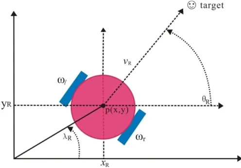
1][2], while the task of the service robot is to set up and clean tables in a controlled environment without a stereo camera. Based on Figure 11.1, is the linear velocity, is the angular velocity, and are radial and angular coordinates of the robot [6].
Stereo Imaging Model


![Figure 1.13 Example of Vision-based Navigation system for Humanoid robot HOAP-1 [12]](https://thumb-ap.123doks.com/thumbv2/azdokorg/8356928.79779/26.680.121.585.520.822/figure-example-vision-based-navigation-humanoid-robot-hoap.webp)
![Figure 1.14 Intelligent Telepresence robot using omniwheel and controlled using Web [11]](https://thumb-ap.123doks.com/thumbv2/azdokorg/8356928.79779/27.680.97.611.423.661/figure-intelligent-telepresence-robot-using-omniwheel-controlled-using.webp)