This is to confirm that TERRY TEH (ID No: 19ACB02136) has completed a final year project titled "PACKET LOSS CAUSE ANALYSIS IN WIRELESS NETWORKS". I declare that this report entitled "PACKET LOSS CAUSE ANALYSIS IN WIRELESS NETWORKS" is my own work except as indicated in the references. Packet loss means that information sent to end users will result in an incorrect state.
Regardless, very few or none of the studies discuss determining the actual reason for packet loss.
Introduction
- Problem Statement and Motivation
- Project Scope
- Project Objectives
- Contributions
- Background Information
- Introduction of Wireless Sensor Networks
- Wi-Fi Standards
- Definition of Packet Loss
- Recent Works
- Report Organization
The simulation results will consist of how accurately the base station will be able to distinguish the reason for packet loss caused by malicious discards or network issues. In addition, this project also aims to improve the IDS or algorithm with a method that will be able to distinguish the cause of packet loss. The algorithm will be used in the base station to analyze the reason for packet loss when it detected packet loss while receiving packets from all the sensor nodes.
Moreover, packet loss is one of the hottest topics in the wireless security area.
Literature Review
Previous work on Intrusion Detection System (IDS) in Wireless Sensor Networks (WSN)
Because global agents can receive packets from both their neighbors and the next hop (due to the broadcast nature of communications), they can be ready to determine whether a particular node discards or modifies packets by analyzing them. However, studying the network would be an energy-intensive task if all global agents were engaged and listening to their neighborhoods at the same time. Consequently, only a fraction of the nodes need to activate their global agents to cover all communications in the sensor network.
The spontaneous watchdog will monitor the entire traffic of the specific package and store all information.
Previous work on detection of selective forwarding attack
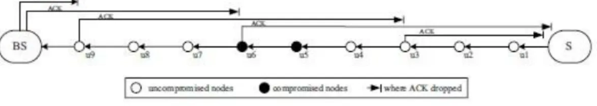
- Lightweight multi-hop acknowledgement-based detection scheme
- Multi-dataflow topologies (MDT) scheme
Since the intermediate sensor nodes must be responsible for forwarding data packets from the source sensor node to the base station, generating ACK packets, and detecting malicious sensor nodes at the same time, it causes communication overhead. Because the detection area overlaps, the base station can retrieve the lost data using alternative data flow topologies. Take Figure 2-2-4 as an example, if a malicious sensor node appears in topology A, the base station will not be able to receive the data packet sent from topology A due to packet loss.
All the intermediate sensor nodes and source nodes just do their respective tasks, such as detecting the area and forwarding the packets to the base station.
Previous work on packet loss analysis on Wireless Sensor Networks (WSN) .1 Impact of packet loss consideration on LEACH routing protocol
- Performance analysis on AODV routing protocol
First, the base station will be able to continuously receive data packets containing the detection area's information, even though some malicious nodes perform a selective forwarding attack. In some sensitive situations, the base station cannot tolerate some data packets being delayed. However, using the multi-data flow topologies can avoid this situation as the base station can still receive the sensitive information through the other topology. Third, the data packet does not need to find another routing path to retransmit the data packet to the base station, allowing the base station to respond to the sensitive events immediately.
The average delivery rate of successful packages, expressed in packages per round, is the network's throughput target. 13] had also done empirical research on performance analysis of wireless sensor networks by varying the reporting rate in the AODV routing protocol. In their study, network simulator NS-2 is used to investigate the performance of Quality of Service (QoS) settings in a wireless sensor network by varying the reporting rate.
First, when the number of packets in the network is low, the Packet Delivery Ratio (PDR) increases somewhat because no packets are dropped, and the PDR is the highest at a reporting rate of 20pps. Second, as the number of packets in the network grows, the number of packets handled by each node per unit of time also increases, resulting in increased throughput. However, when the network's traffic grows, the delay of the reporting rate is found to grow as well.
When the amount of packets in the network grows, the routing overhead also grows. For a reporting rate of 50pps the routing overhead is at its highest, minimum at reporting rate of 20pps.
System Model
- Network Model/Overview
- Methodologies
- Implementation Issues and Challenges
- Timeline
- Software Setup
- OMNeT++ Installation
- INET Framework Installation
- Setting and Configuration
- Network Description File (NED)
- System Operation
- Concluding Remark
This will be used to simulate the malicious discarding of the packet in the network. The radio interference will be placed between the base station (BS) and one of the neighboring nodes of the BS. First, the malicious node will be configured at one of the neighboring nodes of the base station (BS).
As mentioned in the previous chapter, this project will use the OMNeT++ network simulator and the INET framework to simulate the network model situation. This sub-section will discuss the settings and configuration of the network simulation configuration. Second, you will configure some of the animations to make the network simulation clearer to observe the result.
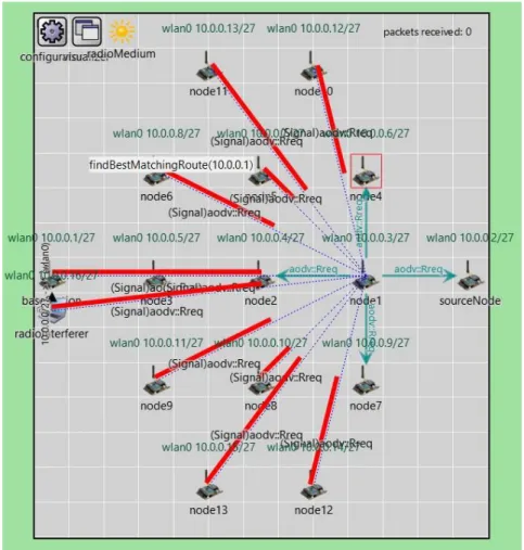
Third, a routing protocol is configured in each of the nodes to allow the packet to travel from the source node to the base station. This section will show the entire operation of the network simulation from the beginning to the end of the simulation. It can be observed that a total of 15 nodes are installed in the network field, including one source node and a base station, along with one radio jammer.
The source node and base station are aligned on the centerline of the network. You can see that part of the "aodv:Rreq" is exchanged to find the least hop path from the source node to the base station. Part of the routes are also discovered from node 3 to the base station and from node 2 to node 3.
Chapter 5 will discuss the network simulation evaluation and some challenges of this project.

System Evaluation and Discussion
- Network Model Observation
- Observation without Network Interference
- Observation with Network Interference
- Network Model Discussion
- Discussion without Network Interference
- Discussion with Network Interference
- Objectives Evaluation
- Project Challenges
After some time, a route was formed from the source node to the base station as shown in Figure 5-1-4. It can be observed that if the network interferes, the base station will receive only 123 packets from the source node. From the previous observation, the network simulation will begin with the AODV routing protocol discovery.
This is because the network is in this situation without any interference from any source. All the packets sent by the source node are successfully received by the base station. The source node will also start sending the UDP packet to the base station once the AODV routing protocol is completed.
From the above two figures, it can be seen that the number of packets sent by the source node and the number of packets received by the base station are different, which in this case is also different from the previous scenario where the network is free of interference. All intermediate nodes between the source node and the base station in the network model will generate an ACK packet and send it back to the source node, which means that they have received the data packet generated by the source node and successfully forwarded it to the next hop. node. Based on this confirmation, the source node will determine if there is a malicious node in the network.
As mentioned many times in the previous chapter, the network simulation will use the OMNeT++ network simulator and the INET framework library. However, the generation of network interference by a radio intruder to intentionally generate packet loss has been.
Conclusion and Recommendation
Conclusion
First, the network simulation model was discussed such as the traffic, nodes configuration, network setup, etc. Second, the methodologies used to achieve the objective of this project were discussed. This project used the detection scheme of [10] as a reference to produce the methodologies such as the generation of the ACK packet.
The issues like the malicious node and radio interferer configuration as the capabilities of the network simulation tool are limited. The challenges will be that the OMNeT++ network simulator uses a different language which is the Network Description (NED) language, so it took some time to get familiar with it and its library needed to build this project. Furthermore, also discuss the INET framework to be installed in the OMNeT++ network simulator as this project requires the INET framework library.
It contains a network description (NED) file and a configuration INI file to set up the network simulation. Finally, the entire network simulation operation is shown to guide users through the entire simulation process. The discussion of the network model includes the observation of the network model and the discussion of the network model of the simulation result.
Unfortunately, this research project was unable to achieve its goal due to the difficulty in implementing the network model. However, there are still some of the works that could be used as a reference to suggest the method to achieve the project's goals.
Recommendation
Finally, this project consists of several challenges such as there is a lack of information relevant to the subject of this project, and everything has to start from scratch.
Bin, "Detecting selective forwarding attacks in wireless sensor networks," i 20th International Parallel and Distributed Processing Symposium, IPDPS vol. 11] Hung-Min Sun, Chien-Ming Chen og Ying-Chu Hsiao, "En effektiv modforanstaltning til det selektive videresendelsesangreb i trådløse sensornetværk". Gontean, "Packet loss analysis in wireless sensor networks routing protocols," i 2012 35th International Conference on Telecommunications and Signal Processing, TSP 2012 - Proceedings, 2012, s.
Yuanfu, “Selective Forward Attack Detection Using Watermark in WSNs,” in 2009 Second ISECS International Colloquium on Computing, Communication, Control, and Management, CCCM vol.
APPENDIX
FINAL YEAR PROJECT WEEKLY REPORT
WORK DONE
SELF EVALUATION OF THE PROGRESS
Pleased with the progress completed as expected, just had some issues with the simulation model. Find out the source library of the INET framework to check if it can be changed.
PROBLEMS ENCOUNTERED
However, the same issue from the last two weeks, have to find a way to modify the source code of the INET framework. The network simulator cannot yet be adjusted to modify the source code library to produce the intended result. However, the simulation model is not satisfied as the result is not intended and may not reach the target.
POSTER
PLAGIARISM CHECK RESULT
CHECKLIST
UNIVERSITI TUNKU ABDUL RAHMAN FACULTY OF INFORMATION & COMMUNICATION
TECHNOLOGY (KAMPAR CAMPUS)
