Lim Chong Hooi for his invaluable advice, guidance and great patience during the research development. For the movement of the robot's transmission and the manipulator arm, ultrasonic sensors and a camera were used to find the position of the rubber trees and the latex cups, respectively.
Background
Therefore, it verified the use of robots in the field of agriculture that increase productivity and increase quality by reducing labor costs and operating time (Pant et al., 2019). In addition, due to the outbreak of COVID-19 that spread throughout the world, several forms of restrictions were imposed on social and economic activities (Oliveira et al., 2021).
Problem Statements
34;Younger people these days don't think it's worth tapping rubber," said Ab Manap Minhat, a rubber worker, in an interview with Channel News Asia, CNA (Tan, 2020). This is because rubber workers receive lower wages. and tend to be involved in much more comfortable and well-paid jobs. In addition, there is a high demand for latex surgical gloves and other latex medical products in Malaysia due to the outbreak of COVID-19 (Tan, 2020).
Aims and Objectives
However, Malaysia, a latex producer, has to import rubber from other countries to make up for the lack of local production because total consumption is greater than local production, Zairossani, Malaysian Rubber Board director told CNA (Tan, 2020). Workers can leave the latex overnight instead of collecting it after just a few hours of tapping.
Scope of Project
Outline of Report
Introduction to Latex
Agricultural Robot in Harvesting Process
Challenges faced to Introduce Agricultural Robot
For example, driving a robot from tree to tree and sensing, grasping and separating fruits requires many algorithms and formulations of sensorimotor control (Ceres et al., 1998). With existing knowledge and technologies, robots will cause manufacturing inefficiencies that include long cycle times and low detection rates (Zhao et al., 2016).
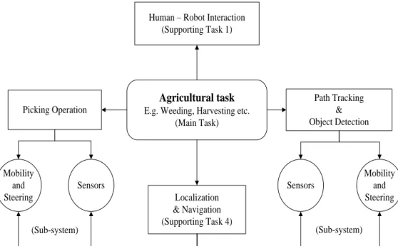
Components of Agricultural Robot
- Sensing
- Planning
- Mobility
- Manipulation
Sensibility is the perception of the surroundings and their occupied objects, which can allow or prevent the operation of the robot (Fue et al., 2020). Path planning is considered one of the most demanding “support tasks” for agricultural robots (Bochtis, Sørensen, & Busato, 2014).
Design concepts
Design concepts for mobility
- Locomotion
- Transmission
- Steering
- Suspension
It is much more expensive compared to the differential drive of the vehicle on the road. In addition, due to constant wheel slip, this steering system is said to be energy-wasting, and the wheels break down more quickly (Kozlowski and Pazderski, 2004).
Design concepts for manipulation
- Manipulator
- End Effector
Furthermore, both sides of the swing link are connected to each other by a rod called a differential arm. However, due to pressure losses and air compression, the efficiency of the pneumatic manipulator will be affected (Gonzalez, 2015).
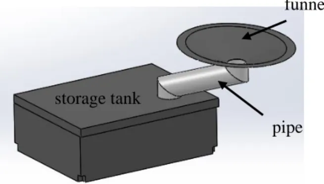
Design concepts for storage tank
Chosen Design
Prototype Design and Material Selection
- PLA Material in Solidworks Software
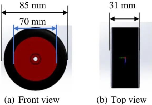
- Locomotion Design (Wheels)
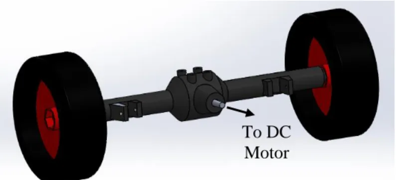
- Transmission Design (Differential)
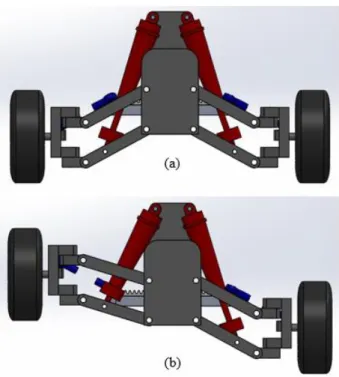
- Suspension Design (Double wishbone and spring)
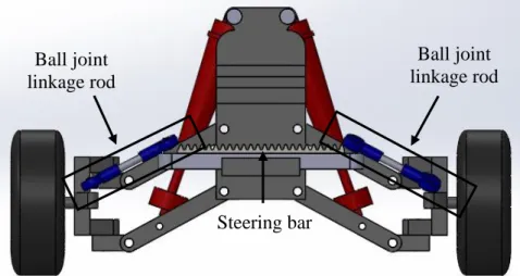
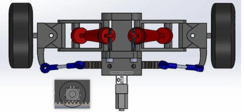
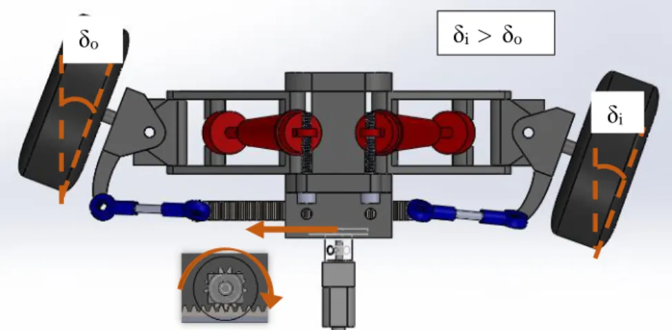
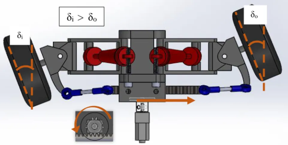
- Steering Design (Ackermann Mechanism)
- Manipulator Design
- End effector Design (Gripper)
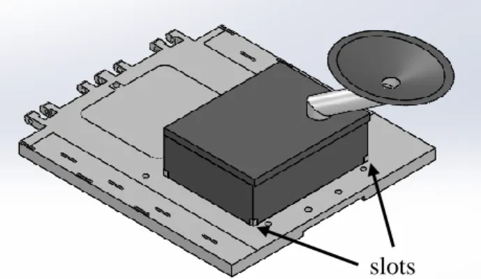
- Storage Tank Design
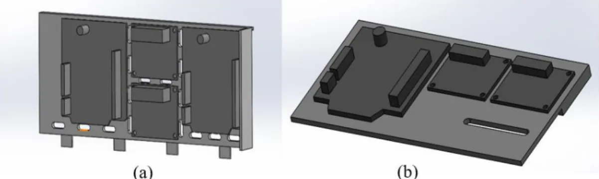
- Electric components storage board
- Base Storage Compartment
- Solidworks Assembly
- Mobility components
- Manipulation components
- Overall Assembly
Also, the mount was designed to be closer to the right because on the left side little space was used to locate the driver's level horizontal arm (Figure 3.20). In addition, the lower right part of the main arm was cut to shape to build a housing for the servo shaft that drives the main arm (see Figure 3.21). The same applies to the driver arm of the horizontal arm, which drives the movement of the horizontal arm (see Figure 3.20 above).
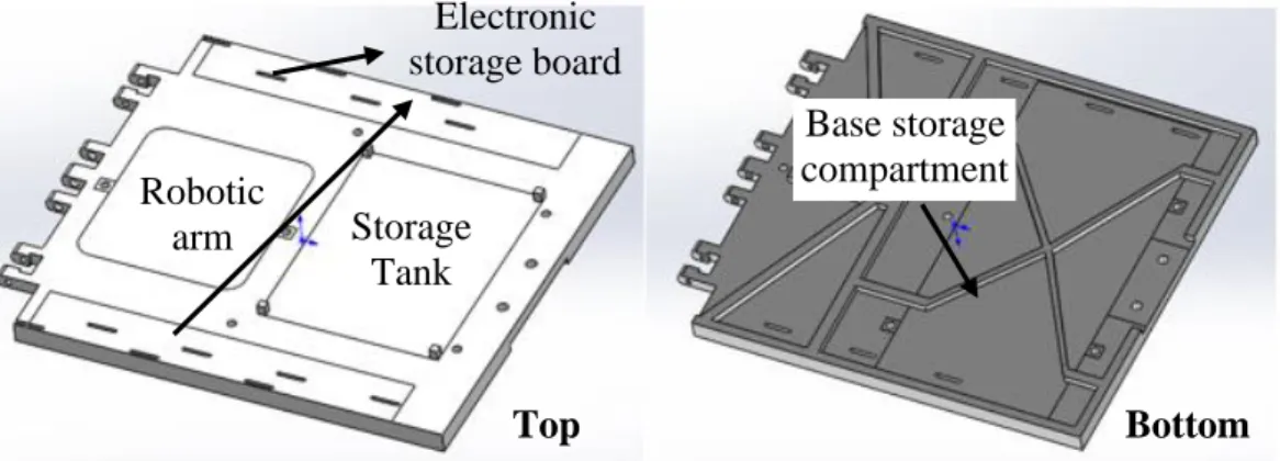
After all the components were placed inside, this compartment was bolted to the robot platform using bolts and nuts (see Figure 3.32).
Firmware configuration
Parameter calculation
- Motor for robot transmission
- Motor for robotic arm
- Motor for gripper rotation (Pouring)
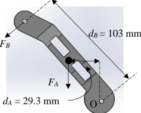
With the existing differential gear in the actual shaft, gear ratio must be considered to determine the torque of the motor. Consequently, the selection of the A58SW-555 12V DC motor in Table 3.2 above is suitable for the robot transmission as the minimum torque required (1.80 kg⸱cm) and the speed required (56.17 RPM) for the motor are within the specification of the chosen car. In this section, the main arm of the robot arm was analyzed to determine the torque.
Therefore, the use of the MG996 servo motor on the main arm is suitable because the stop torque of this servo motor is 12 kg⸱cm while τO is only 1.763 kg⸱cm which is safe to work without falling.
Static Analysis
Robot Platform
The distances between the center of mass and point A were then determined (see Figure 3.40). These two values are then applied to the two square faces that represent the attachment points for the robot arm and the robot platform (see Figure 3.41). In addition, to prevent deformation of certain areas of the robot platform, a clamping function was also used within the joint area.
For example, the back of the robot platform does not want to deform, because it is bolted to the shock absorber of the rear wheel part.
Robotic Arm
In addition, due to the many joints designed on the arm, the pin joint function was applied to each joint to prevent the joint from deforming during the simulation.
Centre of mass: Toppling analysis
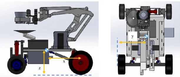
Centre of mass identification
However, this becomes a complicated calculation process as this robot consists of many parts and components. The center of mass can easily be generated by the software itself by choosing the "Center of Mass" function. The different positions of the robot arm and the mass of the robot will change the position of the robot's center of gravity due to the weight shift.
Note that only heavy parts and components are included to simplify the analysis and also because light mass has a negligible effect on the center of mass.
Topple Angle
Motion Study
Motor Feature
Suppose that the motor feature should be applied to the motor shaft, but to reduce the calculated constraint, it was applied to the rear axle and the speed set was 56 RPM, which was already considered the gear ratio calculated in section 3.3.1.1 . .
Spring Feature
After the experiment, the spring constants for the front and rear wheel systems were determined. Other parameters such as spring width, number of cells and wire diameter were measured and entered into the setup for a more accurate simulation run on the robot.
Contact Feature
Then the result was observed to evaluate the availability of the designed robot to encounter the barrier built on the track.
Fabrication of Prototype and Experiment Set up
Experiment setup
- Topple test setup
- Prototype test run
This test was performed to verify the roll angle calculation for the prototype in Chapter 3.4.2. An adjustable laptop stand is used to act as the inclined surface on which the prototype can rest (Figure 3.49). For the prototype test run, the prototype first underwent functional tests that required it to perform the tasks assigned to it.
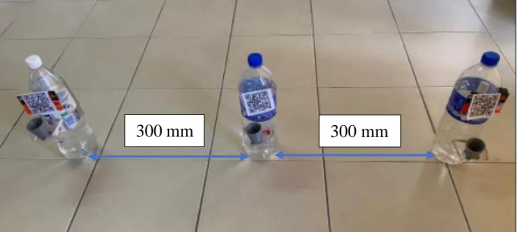
In addition, to test the flexibility of the robot arm, latex cups were placed on three water bottles at three different heights (see Figure 3.51).
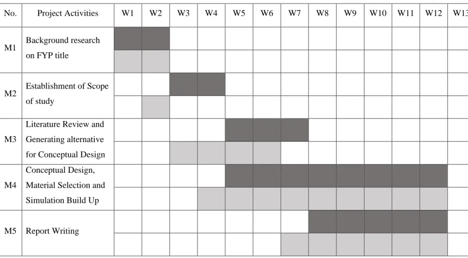
Project Planning and Milestone
Alternative component design concepts were generated and discussed to select an appropriate design for the final conceptual design. If an error occurs, the CAD design change will be made before the prototype is fabricated. Once the final version of the prototype is created, data collection for the experiments, such as running time per cycle, is recorded and analyzed accordingly.
These two charts are used in this project to determine the project planning schedule and keep track of the project's progress.
Latex Cup Collector Robot prototype
Finite Element Analysis (Static Test)
Robot Platform
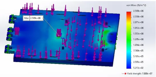
From Figure 4.4, it can be observed that the robot platform deforms largely towards the center, and the red zone representing the largest deformation is on two sides of the robot platform's center. This is because all the designed components are located in the center of the robot platform, which makes them heavier and causes them to deform more in that area. The result of this plot immediately shows the effect in the real case of the robot platform.
For the load result, Figure 4.6 shows that the maximum load is located at the same place as the load plot, which is the front attachment point of the robot platform with the robot arm.
Robotic Arm
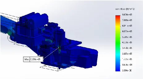
Figure 4.9 shows that the robot arm has a maximum displacement of 1.868 x 10⁻¹ mm at the end of the left gripper. In addition, due to the heavy weight of the gripper support, it has also largely moved from its original position, as shown in Figure 4.9. In addition, for the stress results of Figure 4-10, the largest change in length toward original length is at the lower joint of the main arm, with the highest value being 1.683 x 10⁻⁴ mm/mm.
The torsional force exists in the cross section of the joint and results in the highest stress value.
Centre of Mass: Toppling Analysis
Centre of mass
From Table 4.1, it is observed that the center of mass in the y and z directions of the robot has only slight changes between the 4 different scenarios. When the robotic arm extends to collect the latex cup, the center of mass moves forward 132.08 mm for an empty tank and 132.51 mm for a full tank. But luckily, the center of mass of the robot designed for all four scenarios is located inside the four wheels, ensuring that the prototype does not tip over when traveling and operating on a flat surface.
Topple Angle
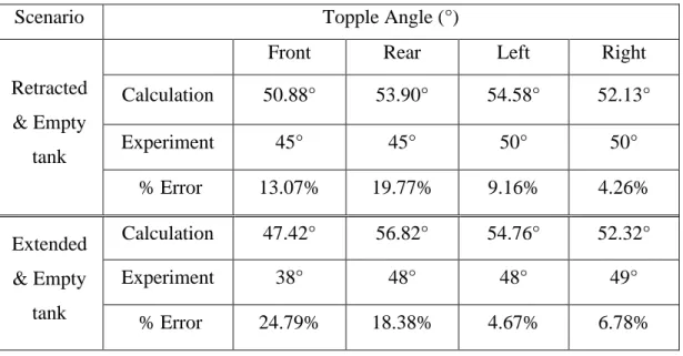
From Table 4.3, it is observed that all the experimental dip angles are smaller than the calculated dip angles. This affects the position of the center of mass on the prototype and then leads to the smaller angle of collapse. However, from Table 4.3, it is observed that the minimum slope angle that the prototype can travel without falling is 39° if the robot has enough power to travel.
And this angle is more than enough for the prototype to travel through the rubber plantation.
Prototype test run
Functional test
Manipulator Test
Mobility Test
Motion Study
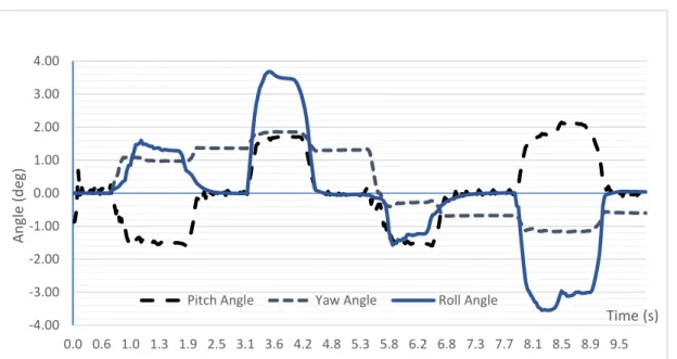
First, talking about the lean angle, the lean angle when the front wheels pass the barriers is about 1.5 degrees, but when the rear wheels pass the barriers, the lean angle is about 1.8 degrees. The springs of the front suspension have a low stiffness per spring length, which makes it easy to compress the springs, resulting in a smaller angle of inclination when passing the guardrails. But it reaches about 3.5 degrees on both sides when the rear wheels pass the barriers.
The reason is due to spring stiffness for suspension systems, which is the same as the reason given in the pitch angle explanation.
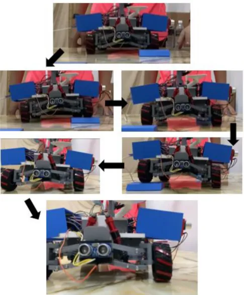
Mobility test run
With this result, it is enough to say that the mobility test run is verified.
Key Findings
Conclusion
Recommendations
Southeast Asia Rubber Markets with Bridgestone, Michelin, Goodyear, Continental, Sumitomo Rubber Industries, Thai Rubber Latex (Thaitex) and Fenner - ResearchAndMarkets.com. Research and design of an autonomous and collaborative self-driving vehicle prototype, to be applied in indoor and outdoor environments and different floor types. Available at: < https://www.researchgate.net/profile/Jyoti-Joshi- 16/publication/351578094_AGRICULTURAL_ROBOTS_THE_NEEDS_AND_.
New differential drive control system with energy saving and normal tire with cylindrical gear for an omni-directional mobile robot.