I declare that this project report entitled "DESIGN OF SCREW EXTRUDER FOR THREE-DIMENSIONAL CERAMIC PRINTING" prepared by WU PENG has met the required standard for submission in partial fulfillment of the requirements for the award of Master of Engineering (Mechanical) at Universiti Tunku Abdul Rahman . And through the use of CAD, the models and parameters of components of the designed screw extruder, such as motor, screw, hopper, barrel and hopper, can be determined exactly, and after designing, through the use of CAE, the printing performance of the designed screw will have been developed, such as pressure of ceramic slurry and screw, temperature distribution and printing speed of screw.
General Introduction
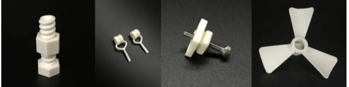
3D printing technology is a new kind of production technology that is developing rapidly in the field of production. Today, ceramic 3D printing is widely used in aerospace, medical science and industrial manufacturing.
Importance of the Study
Problem Statement
Cong riyuan et al, 2019) Therefore, it is so popular that it has been widely used in the field of ceramic preparation at present. But there are some drawbacks to ceramic 3D printing methods, which are shown below as examples.
Aim and Objectives
Although it is simple to operate, low energy consumption and low cost with no pollution to the environment, the materials used in this technology are mostly thermoplastic polymers, which are investigated in ceramic printing and molding. Liu K et al, 2017) Therefore, it is critical to choose a more proper method for ceramic 3D printing, relatively.
Scope and Limitation of the Study
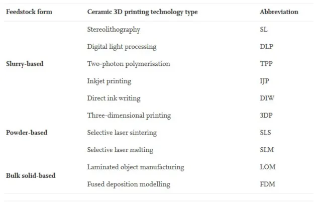
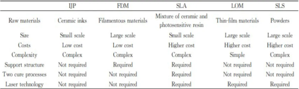
- Inkjet Printing
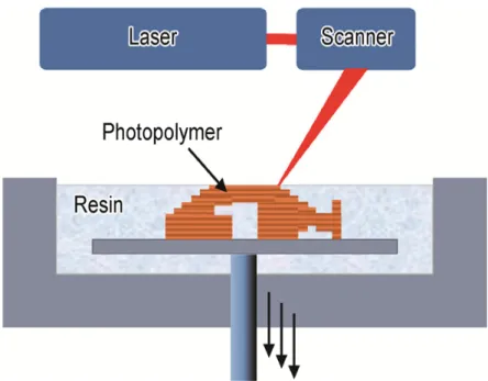
- Stereolithography Apparatus
- Selective Laser Sintering
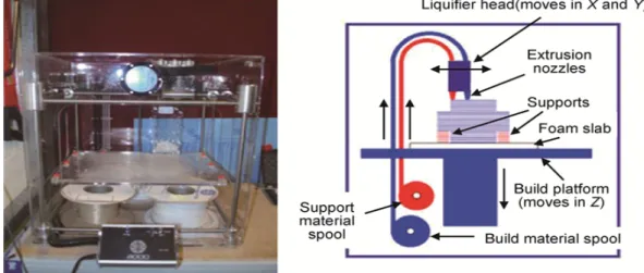
- Fused Deposition Modeling
The finishing should consider the secondary hardening of the molded parts, and the support structure should be removed at the end, which is more complicated. The content and types of organic materials used as binders in the materials directly affect the density and mechanical properties of the ceramic body. The realization principle of the Fused Deposition Modeling technology is simple, but the temperature at the nozzle is high during the 3D printing process, and the requirements for the raw materials are higher.
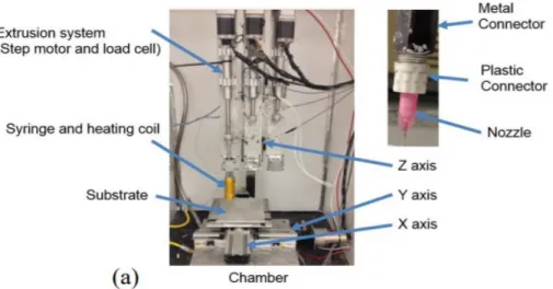
The Research to Slurry Extrusion Device
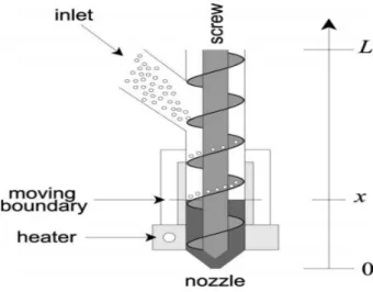
The working principle of the screw extruder is that the pellets are usually held in a hopper and fed into the extruder through the hopper inlet. Buffer room refers to the empty space between the bottom of the pulley and the nozzle. Based on the rotation of the motor, the pellets are compressed in the buffer chamber and forced through the small hole in the nozzle.
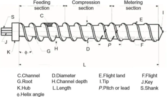
The Review to Extruder Screw
- The Three Sections of Extruder Screw
- The Diameter of Screw
- The Clearance
- The Helix Angle of Screw
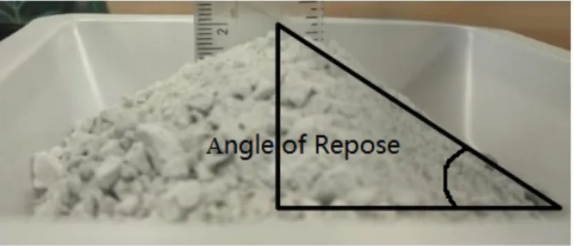
As the diameter of the screw increases, the processing capacity of the extruder increases accordingly. The ratio of the effective length to the diameter of the working part of the screw (called the ratio of length to diameter, expressed as L/D) is usually 10 to 30. The helix angle Φ is the angle between the screw thread and the diameter of the screw.
The Review of Other Components of a Screw Extruder
The Optimization of Screw Extruder
Printing Accuracy
On the other hand, the printing accuracy can be further improved by reducing the nozzle diameter to 0.4mm, but during the test, the nozzle is easily clogged, and the cleaning requirements of the extruder after the printing experiment are greatly improved with the increase of the cost price.
Outlet Flow Rate
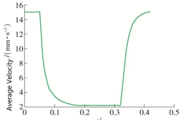
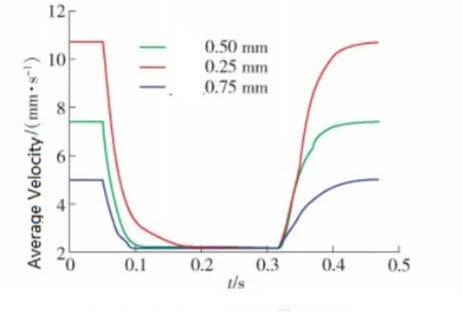
On the other hand, the smaller the clearance on the inner wall of the barrel, the less slowly the exhaust flow rate will decrease when the propeller stops. And the faster the exhaust flow rate increases when the screw rotates again, showing that the clearance may play a role in releasing the internal pressure of the screw extrusion device. When the length of the variable pitch part of the screw is set to 10 mm, and the screw groove depth is changed from 12 mm to 24 mm.
The Properties of Alumina Ceramic
The simulation results are shown in Figure 2.11, the maximum output flow can reach 15.07mm/s, so the printing speed can be set to 15mm/s, which achieves the optimization purpose of improving printing quality and printing efficiency. Therefore, alumina ceramics have good mechanical properties, high temperature properties, electrical properties and chemical stability.
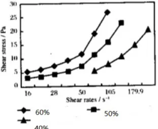
The Review of the Rheological Behavior of Alumina Ceramic
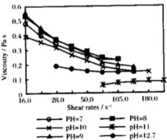
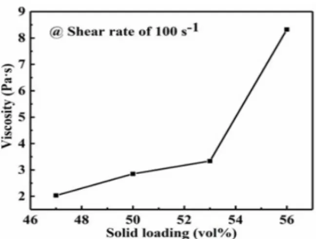
The viscosity of the former is independent of shear stress, and the viscosity of the latter is a function of shear stress. When the pH is less than 10 and alumina at low shear rate. The viscosity of the slurry decreases with the increase of the shear rate, and the viscosity of the alumina slurry increases with the increase of the shear rate when the PH value is greater than 10 and at a high shear rate. The viscosity of alumina slurry increases gradually with the increase of solid phase content (47 vol%~56 vol%).
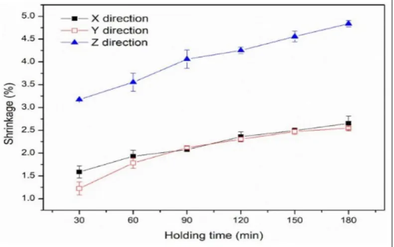
The Review to the Process Ceramic Sintering
His experiment showed that the green body of aluminum with a grain size of 4-8 nm could be completely dense after melting for 15 minutes. While the green aluminum body with grain size 50-100nm sintered under the same conditions had the relative density which could only reach 89% of the theoretical density. The research showed that the aluminum body with a particle size of 0.2μm was almost completely dense (relative density greater than 98%) after 100 minutes, while the body with a particle size of 1.8μm was far from dense (relative density is less than 85%), which also showed that the finer the aluminum particles, the easier it was to melt and the lower the sintering temperature.
Introduction
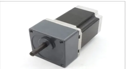
The Design of Motor
The variable gear set is arranged in the gear box and a gear hole is provided in the middle of the bottom plate of the gear box. The second gear hole is provided at the middle location of the first gear holder. The part of the output shaft that extends outside the cover forms the stepper motor output shaft of the gearbox.
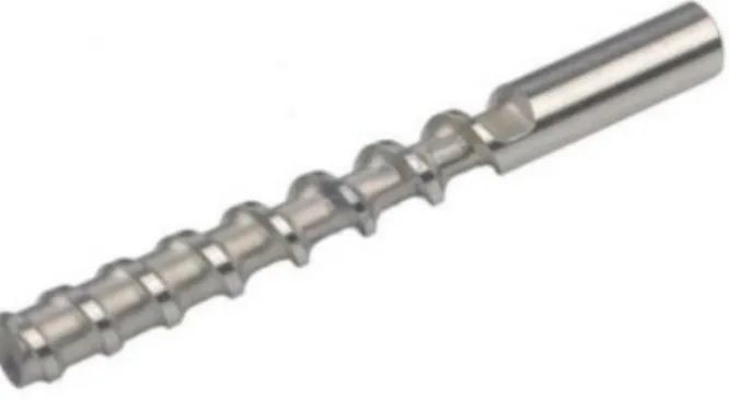
The Design of Extruder Screw
And the L/D ratio is the ratio of the length of the screw to its outer diameter. The helix angle is the angle of the screw thread relative to a plane perpendicular to the plane of the screw. If the helix angle is too large, the plasticizing time cannot be guaranteed, and the plasticizing quality of the screw will decrease.
The Design of Hopper
The position of the hopper is one of the influencing factors on the extraction effect of the screw, when the distance H1 between the hopper entrance and the screw tip is too large, the screw has a weak pulling effect on the ceramic, which cannot accurately. check ceramic ejection and stopping. If the distance H1 between the inlet and the tip of the screw is too small, the pushing effect of the screw will be. In general, the ratio of the distance H1 between the hopper inlet and the screw tip to the screw length H is equal to about 0.4, which has a better extraction performance, which is shown in Figure 3.8.
The Design of Barrel
The gap between the screw and the barrel has a very important influence on the performance of the extruder. The gap here refers to the one-sided clearance between the inner wall of the barrel and the outer wall of the screw. When the gap becomes smaller, the shear force of the extruded material will increase, and the friction between the screw and the barrel will be too violent, resulting in locking.
The Design of Nozzle
The size of the gap determines the flow rate, return flow rate and shear stress of the extruder. Looking through the literature, it is concluded that the clearance should be controlled to about 0.25 mm between the cylinder and the screw. So the line width in the project can be easily calculated, which is equal to 0.6mm when the flat width is equal to the nozzle size.
The Design of Heating Block
The working temperature of the heating block has a range of 105°C to 135°C to melt the alumina-LDPE composite material. The heating block is designed to be installed on the barrel of the extruder to ensure even heating all around. Thermistor will feed the temperature of the heating pad back to the system to regulate the power sent to the ceramic heater cartridge.
The Calculation Involved in the Design
Output Flow Rate Model
By measuring the parameters of the screw shown in Figure 3.13, the flow can be easily calculated.
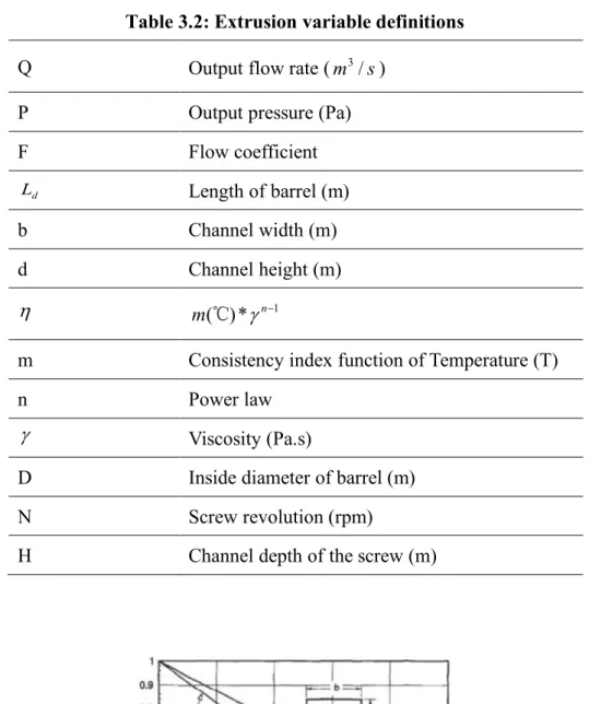
Max Output Pressure
It can be concluded that when the exit pressure reaches the maximum value, the exit flow rate Q will be 0. In addition, the pressure drop at the exit of the extruder will usually be less than the maximum exit pressure.
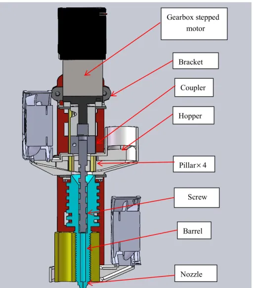
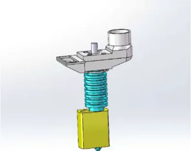
The Assembly of Screw Extruder
To fix the hopper to the extruder, it is necessary to use four pillars shown in figure 3.14, which connect to the bracket and the hopper (there will be four small holes and a large hole in the middle for the four pillars and the screw to pierce, respectively, shown in figure 3.15.At the bottom of the funnel there will be another bracket to support it, which also fits on the four pillars.Here the barrel is designed to be equipped with a steel gasket shown in Figure 3.14, and it relies on the gasket to be connected to the bracket located at the bottom of the hopper by means of the screw connection.
The Simulation to the Screw Extruder
Then, the pressure is set to 101325 Pa, the temperature is set to 20.05 degrees Celsius, and the flow rate of each component is set to 0, which means the simulation is performed at room temperature and pressure, shown in Figure 3.19. After that, the step is to set the boundary conditions including the design extruder component material, heat source temperature and screw rotation, shown in Figure 3.20. Due to the small size of the nozzle, in order to ensure the accuracy of the position calculation, it is necessary to carry out further local check of the grid in this area and adjust the liquid grid, solid grid and level grid. delivery to the nose at 7, shown in figure 3.20.
Introduction
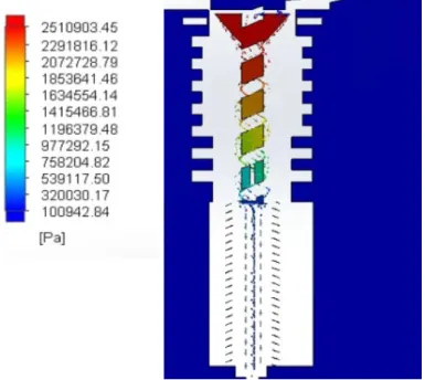
The Static Pressure of Screw Surface and Ceramic Slurry
After screw extrusion, it gradually becomes a slurry and its flow rate gradually increases. Above the auger, the slurry enters at a lower speed from the external inlet, but the pressure is higher. When the slurry enters the barrel, it is accelerated by the rotation of the screw, the speed increases slightly, and the pressure gradually drops.
The Analysis of Heat Transfer
It can be concluded that the surface temperature of the hopper at its inlet is lower than 30℃ and the temperature rises to about 50℃ at its outlet, which is lower than the heat distortion temperature of PETG (69~70℃ ). On the other hand, the glass transition temperature of aluminum and LDPE pallets is about 80℃, so it ensures that the aluminum and LDPE pallets will not melt in the hopper, causing material blockage at the outlet of the hopper, which verifies that the sheet made of PETG can be used in this project for 3d printing.
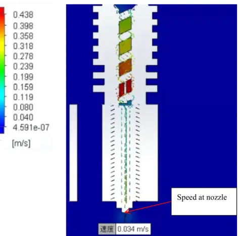
The simulation to Flow Trace and Speed
To verify whether the fluid movement process is consistent with the actual situation, the flow path of the model is checked, shown in Figure 4.4. It is concluded from the flow-trace graph that the fluid enters from the inlet, then flows through the internal spiral structure, and is then ejected from the nozzle. The velocity change during the fluid flow is consistent with the actual situation, indicating that the simulation in this project meets the actual requirements.
Outlet Pressure Measurement
Conclusion
In the part of heat transfer, the temperature distribution decreases from the heat block to the funnel. Then the flow trace simulation verifies that the slurry can move down smoothly without any coincidences, which is consistent with the real situation. Finally, by switching to the speed distribution graph, the speed at the nozzle is 34mm/s, which is between 30mm/s and 45mm/s for ceramic printing.
Recommendation for Future Work
Moreover, since the screw extruder model has been completed, the further work can be to simulate the static pressure on the mixture surface and the screw, the temperature and velocity distribution at the exit, etc. using other raw materials for 3D printing. Effect of filler diameter on UV transmittance and dielectric constant of aluminum oxide used for stereolithographic 3D printing. Effect mechanism of nano-alumina content in semi-solid ceramic precursor fluid on transformability: by light-polymerized 3D printing method.