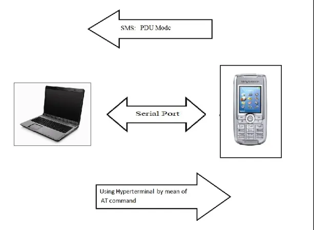
I would like to thank everyone who contributed to the successful completion of this project. Mobile phones can be used to send short message services (SMS) and they will be received by a GSM mobile phone which functions as a GSM modem. There will be some standard instructions in the messages that can be interpreted by the microcontroller that is connected to the deployed GSM mobile phone.
Programming will be done in order to give priority to the instruction of the most recent message to be executed. The PLC modem will be a simple form of circuit that can be plugged into any power line outlet in a building.
Background
Objectives, Aims and Motivation
Focus and Task Distribution
Project Outcome
Global System for Mobile Communication (GSM)
- The Structure of GSM Network
- GSM Service - Short Message Service (SMS)
- Cellular Radio Network
- Hayes Command Set (AT Command)
The network and switching subsystem (the part of the network that most closely resembles a wired network). It provides features such as out-call switching and mobility management for mobile phones roaming on the network of base stations. It is used by telecommunications service providers to support processes such as maintaining network inventory, delivering services, configuring network components, and managing faults.
Mobile phones can connect to GSM (cellular network) through nearby cells, with each cell's coverage area varying depending on the implant environment. The Hayes command set is a specific command language originally developed in 1977 for the Hayes Smartmodem 300 baud modem. The command set consists of a series of short text strings that combine to produce complete commands for operations such as dialing, hanging up, and changing the connection's parameters.
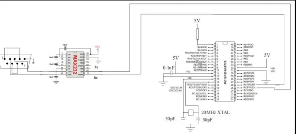
MAX232
Universal Asynchronous Receiver/ Transmitter (UART)
Transmitting and Receiving Serial Data
A UART is used to convert transmitted information between its sequential and parallel form at each end of the connection. Each UART contains a shift register which is the basic method of converting between serial and parallel forms. Typically, the UART usually does not directly generate or receive the external signals used between different devices.
Therefore, separate interface devices are used to convert UART logic level signals to and from external signal levels. Many chips provide UART functionality in silicon, and there are inexpensive chips for converting logic-level signals (such as TTL voltages) to RS-232-level signals (such as Maxim's MAX232).
Recommended Standard 232 (RS-232)
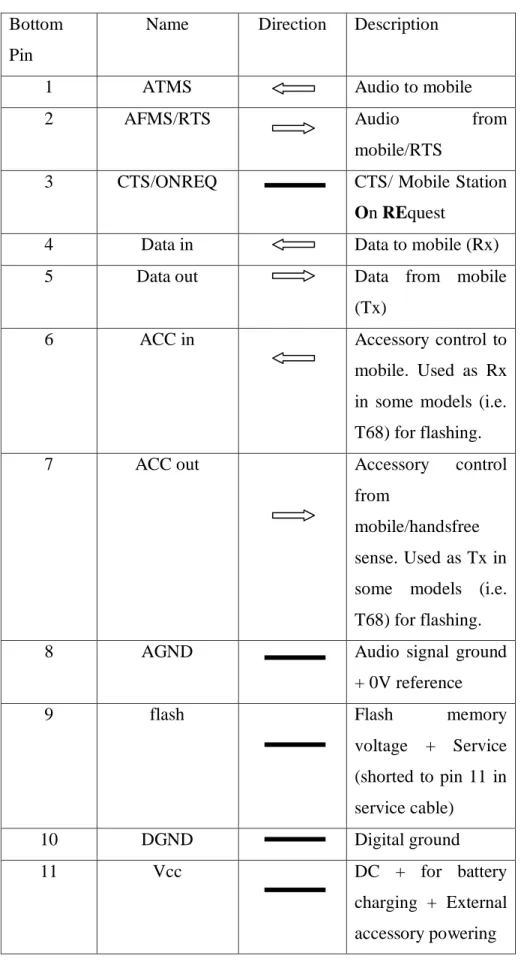
- Connector
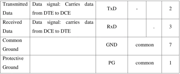
- Pin-Outs for RS232
- Serial Cables
- Limitation of Standard
Data terminal equipment (DTE) or data communication equipment (DCE) determines in each device which wires will send and receive each signal. Standard recommended male connectors with DTE pin functions and modems have female connectors with DCE pin functions. Due to single-ended signaling referenced to a common signal ground, it limits noise immunity and transmission distance.
The use of handshake lines for flow control is not really reliable in many other devices because it is initiated for the setup and removal of a call communication circuit. There will be only a small amount of current that will be extracted from DTR and RTS lines.
Hyperterminal
Hardware Implementation
Overall Concept of the Design
X1 C2 4MHz
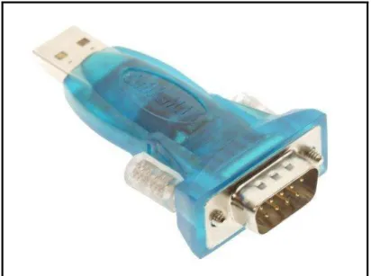
GSM Mobile Phone – Sony Ericsson K700
When the phone and a PC running Windows 2000 or XP are first connected via infrared, a generic modern driver is automatically installed by checking the modem properties and the Sony Ericsson modem driver is installed. This can be done by adding the PC to the phone's list of Bluetooth devices. Initially, the cable must be installed by accessing the software driver for the cable.
PIC16F877A
Software Implementation
- Operating Mode: SMS Text Mode and SMS Protocol Description Unit (PDU) Mode
- Text Mode
- Protocol Description Unit (PDU) Mode
- Comparison of SMS Text Mode and SMS PDU Mode
- Short Message Service Center (SMSC)
- Syntax of SMS AT Commands and Responses
- Defined Values for Certain Parameters
- Input/Output Format of SMS Messages Used by SMS AT Commands
- Ease of Use
There are two ways to send and receive SMS messages, either text mode or PDU mode. In SMS Text mode, a single short message can have a text length of 160 characters, which is 7-bit encoded, or 140 characters, which is 8-bit encoded. In SMS text mode, the only way to specify the service center address to be used by +CMGW and +CMGS is via +CSCA.
However, in SMS PDU mode, it is possible to specify the service center address in the +CMGW and +CMGS AT commands directly as a parameter value. Given a situation where using SMS text mode to send SMS messages "It's easy to send text messages." The command lines are as follows. However, if in SMS PDU mode, running the above command line will throw an error.
This is because the syntax of the +CMGS AT command is different in SMS PDU mode. Usually, string values are defined for text mode, while numeric values are defined for PDU mode. In SMS text mode, headers and body of SMS messages are imported/exported as separate parameters or fields.
In SMS PDU mode, Transport Protocol Data Units (TPDUs) are loaded and unloaded in hexadecimal format. But when it is necessary to send the same SMS message as SMS PDU mode,. Based on previous examples, it is easier to use AT commands in SMS text mode, where it is more direct.
Alternative to Avoid Rewiring Other Than using Power Line Communication – (Ultrasound)
- Ultrasonic Sensor
- Ultrasonic switch
- Ultrasonic Transmitter
- Ultrasonic Receiver
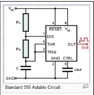
Therefore, the circuit is designed in such a way that ultrasonic waves are transmitted through air. Timer IC555 is an integrated circuit to provide pulse generation, oscillation and timing diversity. In this project, the astable will be discussed because it works as an oscillator to provide pulse generation.
To get the desired frequency of ic555 timer the following equation can be applied. An ultrasonic receiver will be used to detect an ultrasonic signal as the switch of the transmitter is pressed. The output of the operational amplifier will be used to turn on a relay that can be used to control any home electrical appliances.
Extended Project (Home Security System – Burglary Notification System)
A Rough Work Distribution Graph
Flow Chart for Burglary Notification System
LCD as Monitoring Tool
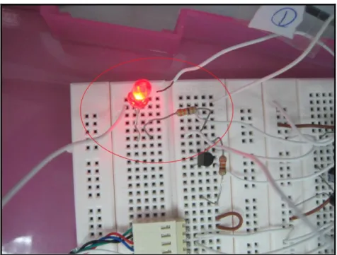
- Sample Code to Turning On a LED
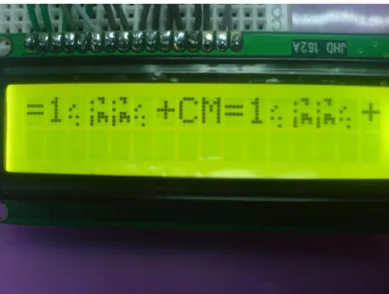
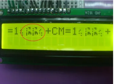
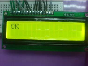
When a "sw off" message is received, an LED of port RD2 will be turned off, and the incoming data from the GSM phone will also be displayed on the LCD screen. LCD can only display ascii codes, whereby unidentified data will be replaced by other symbols.
Communication between PIC16F877A and Hyperterminal
- Code Testing for Checking PIC16F877A and Hyperterminal Communication
To check the communication, an example code is written which sends a string of character through the PIC16F877A to the hyperterminal (the data is shown on . the hyperterminal interface) and any feedback (typed in hyperterminal using keyboard) will be displayed on the LCD. If the entered data is shown on the LCD, it shows that the hyperterminal and microcontroller are well communicated.
Communication between SE K700i (GSM Modem) and PIC16F877A
Receive Error from GSM Phone
- Investigation and Solution on Receiving an Error
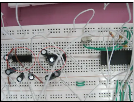
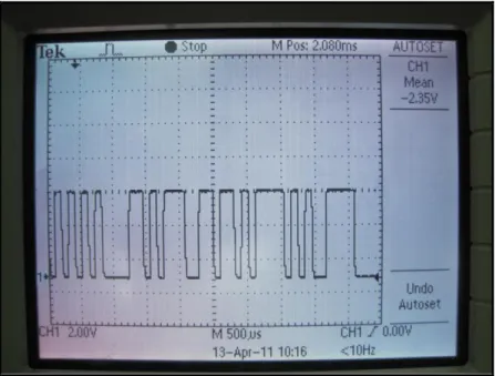
To investigate the causes of the problem, the digital oscilloscope is used to check the incoming data from the GSM phone (The probe is preferable to the common cable for more accurate results because the probe provides the lowest noise). Based on the oscilloscope, the input signal from the GSM phone has an amplitude of 3V peak-to-peak instead of the input voltage of 5V peak-to-peak. This is the main cause of getting an error input due to the failure of the microcontroller to detect the weaker signals.
Therefore, two 5V boosted max232 ICs are used to trigger the signals to 5V, which is the appropriate input signal for the pic16F877A.
Coding Errors
- Problems Caused by Polling in Coding Structure
- Sample Code for Using Polling Structure
- Explanation for Sample Code
- Problem Caused by Interrupts Sub-Routine (ISR) Function
- Sample Code for Using ISR Functions
- Explanation for Sample Code
- The Problem is Solved by Fuse-in Polling Structure and Interrupt Function
- Sample Code of Calling Transmit Function and Using Receive Interrupt Function
- Explanation for the Sample Code
- Special Remark for Using Receive Interrupt Function
- The Limited Size of Array
- Sample Code to Clear the Array
- Echoes from GSM Phone
When the polling method is used, some of the received data will be corrupted and may not be fully delivered to the PIC16F877A. This is because the data transfer rate is too fast when the get function is too late to be called, causing some of the data to not be buffered in time. Interrupt functions are used whenever an interrupt flag is activated, the main code will stop and jump to the interrupt function.
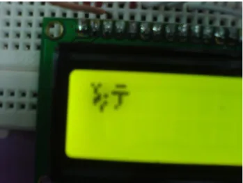
After the task in the break function completes, the main coding will continue to run. However, if the transmit function is used as a transmit interrupt, it will also cause an error where the microcontroller will get black square (as shown on the LCD). Once the input is detected, it will be stored in a buffer without the need to wait for the broadcast function to complete.
In addition, the ISR function must be completely free of any instructions other than storing the received data in the buffer. Array size only up to 95 characters (average should be up to 125 characters, but due to microcontroller memory allocation only 95 characters remain). The contents of the array will be used to compare and perform some switching tasks.
Echoes mean whatever is sent on the command will be reflected back to the input before responses are received for the command. Echos can be turned off by sending AT command, ATE0 to the GSM via microcontroller. The purpose of turning off the echoes is to save places (arrays) for the responses (data).
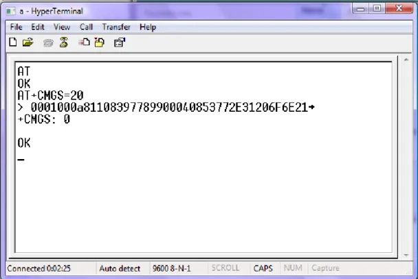
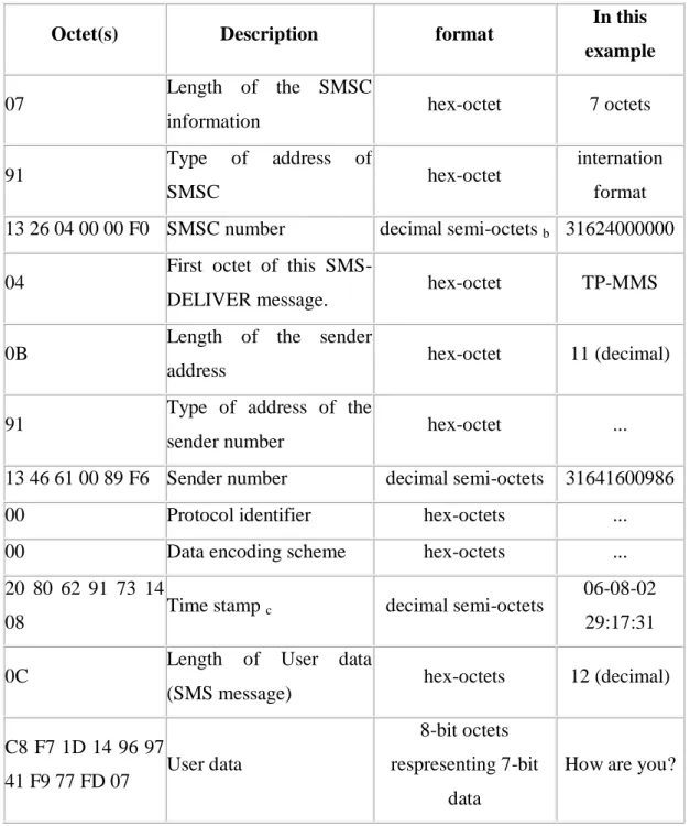
The Analysis of PDU Mode for Sending SMS
Ultrasonic Transmitter
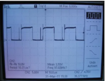
- Checking the Transmitted Signal Using Spectrum Analyzer
The transistors will drive the ultrasonic transmitter which will vibrate at 40 kHz generating ultrasonic waves. The signal can be adjusted by adjusting the variable resistance on the transmitter circuit to obtain the required transmitted signal frequency.
Ultrasonic Receiver
Table of Signal Sensitivity for the Ultrasonic Switch
Encountered Problems for the Ultrasonic Switch
Home Security System (Burglary Notification System)
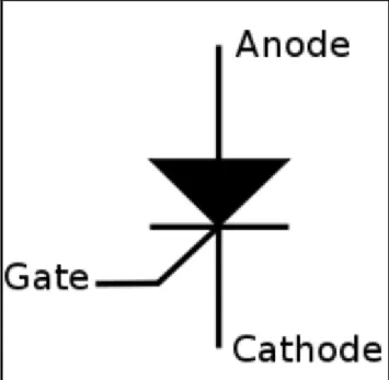
- Remedy-SCR circuit
- SCR Unable to Notify Microcontroller
- Solution- NAND Gate
- Coding to Trigger the Burglary Notification System
When the SCR gate is triggered (at least 1 second), it will turn on continuously unless the power supply is turned off. But when it is triggered, it can only supply the output voltage from the SCR, which is about 0.7V. When the SCR is not triggered, it provides 5V for the output, the 5V will be fed to the NAND gate, which will output 0V.
This will not notify the microcontroller to turn on the LED (the LED is used to notify that someone has broken). On the other hand, when the SCR is activated, it will provide a 0.7V output, the 0.7V will be fed into the NAND gate to output a 5V.
Conclusion
Potential
This system can notify guards and police officers when a break-in occurs, but without signaling the burglar.
Limitation
Future Recommendation
Available on 18th July 2010 from http://www.sonyericsson.com/cws/products/mobilephones/specifications/t610?cc=us&lc=en.