A STUDY ON THE MECHANICAL EFFECTS OF GAS NITRIDING ON ALUMINIUM ALLOY 6061
FOR THE USE
IN MOBILE PHONE CASING
MUHAMMAD FIRDAUS BIN JINAL AHBIDIN
MECHANICAL ENGINEERING UNIVERSITI TEKNOLOGI PETRONAS
JANUARY 2016
MUHAMMAD FIRDAUS JINAL AHBIDIN B. ENG. (HONS) MECHANICAL ENGINEERING JANUARY 2016
A STUDY ON THE MECHANICAL EFFECTS OF GAS NITRIDING ON ALUMINIUM ALLOY 6061
FOR THE USE
IN MOBILE PHONE CASING
by
Muhammad Firdaus Bin Jinal Ahbidin 16417
Dissertation submitted in partial fulfilment of the requirement for the
Bachelor of Engineering (Hons) Mechanical Engineering
JANUARY 2016
Universiti Teknologi PETRONAS Bandar Seri Iskandar
32610 Tronoh
Perak Darul Ridzuan
ii
CERTIFICATION OF APPROVAL
A STUDY ON THE MECHANICAL EFFECTS OF GAS NITRIDING ON ALUMINIUM ALLOY 6061
FOR THE USE
IN MOBILE PHONE CASING
by
Muhammad Firdaus Bin Jinal Ahbidin 16417
A project dissertation submitted to the Mechanical Engineering Programme
Universiti Teknologi PETRONAS In partial fulfilment of the requirement for the
BACHELOR OF ENGINEERING (Hons) MECHANICAL ENGINEERING
Approved by,
____________________________________
Tuan Haji Kamal Ariff Bin Zainal Abidin
UNIVERSITI TEKNOLOGI PETRONAS TRONOH, PERAK
January 2016
iii
CERTIFICATION OF ORIGINALITY
This is to certify that I am responsible for the work submitted in this project, that the original work is my own except as specified in the references and acknowledgments and that the work contained herein have not been undertaken or done by unspecified sources or persons.
__________________________________
Muhammad Firdaus Bin Jinal Ahbidin
iv
ABSTRACT
The constant demands for low weight and high strength mobile phone casing lead manufacturers to utilize aluminium for the material selection. In this study, heat treatment process will be conducted on Aluminium Alloy 6061 by means of gas nitriding process. In this process, the aluminium sample was heat treated at temperature 550℃ while at the same time nitrogen gas diffused into the surface material after being introduced into the tube furnace. The samples were then tested for its improved properties using Rockwell hardness testing machine and Revetest Scratch Tester for its hardness and scratch resistance. The microstructure test was carried out to examine the formation of nitride layer using Optical Microscope (OM) and Scanning Electron Microscope (SEM) built in with Energy Dispersive Spectrometer (EDS). The experimental results comprised data comparing with both nitrided and unnitrided samples.
v
ACKNOWLEDGEMENT
In the name of Allah, The Most Merciful and Most Compassionate
I would like to thank and express my heartfelt gratitude to the following persons who have supported and guided me in completing my Final Year Project.
Heartiest gratitude I express to Tuan Haji Kamal Ariff Bin Zainal Abidin, supervisor for my project together with Associate Professor Dr. Patthi bin Hussain for their invaluable guidance and encouragement extended throughout the study. Their continuous supervision, suggestion, patience and guidance deserve a special mention.
Special thanks I deliver to these Lab Technologist; Mr. Danial, Mr. Adam, Mr.
Paris, Mr. Irwan and Mr. Hafiz for their co-operation, thoughts and ideas in helping me to understand the projects, preparing samples and support along the way to complete the project. Also not to forget Dr. Mazli for spending his time and knowledge to guide me indirectly for improvement of this study.
In addition, I would like to appreciate my parents and my fellow colleagues for their encouragement, comments and knowledge sharing which really assist me in completing this project. Lastly, I would like to say thank you to whoever has contributed in any way, directly or indirectly in the process of carrying out this project.
vi
TABLE OF CONTENT
CERTIFICATION……….ii
ABSTRACT ... iv
ACKNOWLEDGEMENT……….v
CHAPTER 1: INTRODUCTION..………..1
1.1 Background of Study ... 1
1.2 Problem Statement ... 2
1.3 Objectives... 2
1.4 Scope of Study ... 3
1.5 Project Significance………..……….3
CHAPTER 2: LITERATURE REVIEW ... 4
2.1 Fundamental of Gas Nitriding ... 4
2.2 Aluminium Alloy 6061 ... 5
2.3 Gas Nitriding Process on Aluminium Alloy 6061 ... 6
CHAPTER 3: METHODOLOGY ... 10
3.1 Sample Preparation ... 10
3.2 Gas Nitriding Process ... 12
3.3 Second Sample Preparation... 13
3.4 Microstructure Test………...14
3.5 Hardness Test………..………15
3.6 Scratch Test………..………...15
3.7 Process Flow Chart……….…………16
vii
3.8 Key Milestone………..………...17
3.9 Gantt Chart………..………17
CHAPTER 4: RESULTS AND DISCUSSION ... ....18
4.1 Results and Data Gathering ... .18
4.2 Discussion and Data Analysis ... 30
CHAPTER 5: CONCLUSION AND RECOMMENDATION ... ..31
5.1 Conclusion ... 31
5.2 Recommendations ... 32
REFERENCES ... 33
viii
LIST OF FIGURES
FIGURE 1. Gas nitriding process using ammonia 6
FIGURE 2. Gas nitriding with pure nitrogen 7
FIGURE 3. Barrel nitriding 7
FIGURE 4. Nitrocarburising process 8
FIGURE 5. Sample cut into 12 small pieces 10
FIGURE 6. Cutting with EDM 10
FIGURE 7. Grinding Process 11
FIGURE 8. Samples after polishing 11
FIGURE 9. Gas nitriding equipment 12
FIGURE 10. Nitrogen tank 12
FIGURE 11. Samples after mounting 13
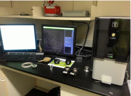
FIGURE 12. SEM equipment 14
FIGURE 13. Rockwell hardness test scale B 15
FIGURE 14. CSM Revetest Scratch Tester 15
FIGURE 15. Unnitrided samples 18
FIGURE 16. 4 hours nitrided Samples 18
FIGURE 17. 8 hours nitrided Samples 18
FIGURE 18. SEM image of nitrided layer for 4 hours 19
FIGURE 19. SEM image of nitrided layer for 8 hours 19
FIGURE 20: Cross sectional line of nitrided layer for 4 hours 20 FIGURE 21. Cross sectional line of nitrided layer for 8 hours 21 FIGURE 22. Line Scanning Profile of nitrided layer for 4 hours 21 FIGURE 23. Line Scanning Profile of nitrided layer for 8 hours 22 FIGURE 24. Element composition on 4 hours nitrided 22 FIGURE 25. Element composition on 8 hours nitrided sample 23 FIGURE 26. Average HRB Value with respect to exposure time of nitriding 24
FIGURE 27. Scratch track on unnitrided sample 25
FIGURE 28. Penetration depth on unnitrided sample 25
FIGURE 29. Scratch track on 4 hours nitrided sample 26
ix
FIGURE 30. Penetration depth on 4 hours nitrided sample 26 FIGURE 31. Scratch track on 8 hours nitrided sample 27 FIGURE 32. Penetration depth on 8 hours nitrided sample 27 FIGURE 33. Decomposition of ammonia in gas nitriding 29 FIGURE 34. Microstructures in all three samples: 30
LIST OF TABLES
TABLE 1. Composition of Aluminium Alloy 6061 5
TABLE 2. Mechanical properties of Aluminium Alloy 6061 5
TABLE 3. Composition of gas mixture 8
TABLE 4. Key milestone of the project 17
TABLE 5. Gantt chart for first semester 17
TABLE 6. Gantt chart for second semester 17
TABLE 7. Thickness of nitrided layer 20
TABLE 8. HRB Reading 24
TABLE 9. Width reading of the scratch tracks 28
TABLE 10. Scratch Hardness Number 28
1
CHAPTER 1 INTRODUCTION
1.1 BACKGROUND STUDY
Metal comes out as the most popular material option for mobile phone casing as its shiny and sturdy looks gives a premium feel to the consumer. Aluminium crafted body have received immense praise as we can see the increasing demand for aluminium casing in numerous models such as iPhone, HTC One Series and many more. The high quality looks of aluminium with precisely-crafted unibody designs giving luxury and exclusive sensation to the owners. Despite the luxurious looks, with rough usage or condition, aluminium casing is proven to experience scratches, bending and wearing of corrosion coatings. In this scenario, it is clear that crucial properties such as hardness will affect the wear resistance of the casing to ensure durable appealing look of the smartphone. Increasing the hardness will increase the wear resistance. These properties can be improved using many techniques and one them is heat treating. Gas nitriding is classified as heat treating process which suitable in enhancing surface hardness of steels containing nitride-forming elements such as chromium, molybdenum, vanadium and aluminium. Aluminium Alloy 6061 is selected as the project material since this alloy is commonly manufactured as the smartphone casing.
2 1.2 PROBLEM STATEMENT
1.2.1 Aluminium has low hardness and wear resistance.
The hardness of aluminium is relatively low due to its low density. It possess poor wear resistance which affects the smartphone handling in rough daily activities.
1.2.2 Additional protective cover equipped is less user-friendly.
Adding protective cover undeniably protect the smartphone body from impact that can damage the internal components. However, this accessory make the smartphone more bulky and inconvenient to be carried in the pocket. Furthermore, equipping protective cover hides the sleek design of the smartphone.
1.3 OBJECTIVES
With regards to the problems stated, this study was carried out to achieve these following objectives:
1. To perform gas nitriding process on aluminium.
2. To study the mechanical effects of gas nitriding on the surface hardness, microstructure and wear resistance of the aluminium.
3. To compare the hardness and wear resistance of nitrided with unnitrided aluminium.
3 1.4 SCOPE OF STUDY
1.4.1 Conducting gas nitriding process on aluminium samples.
Specimen used is a same material as smartphone casing and cut according to the size stated in ASTM standard for scratch and hardness testing.
1.4.2 The study focused on microstructure, hardness and wear resistance of nitrided and unnitrided aluminium.
This study will determine the changes in microstructure, hardness and relationship with wears resistance for unnitrided and nitrided sample.
1.4.3 Carry out the scratch and hardness testing using ASTM Standard.
All procedures for scratch and hardness testing will be following the ASTM standard to obtain credible results.
1.4.4 Performing microstructure testing using OM and SEM
Microstructure testing will be conducted to review the formation of nitride layer on the sample’s surface after the nitriding process using SEM.
1.5 PROJECT SIGNIFICANCE
Aluminium exhibits a high commercial value in smartphone production due to its lightweight and sturdy properties which make it suitable to be designed as a smartphone casing. Since smartphone crafted from the aluminium is costly, improving the surface hardness will increase the time worth value of money for the consumer to buy. Performing gas nitriding on aluminium casing smartphone will increase the hardness and wear resistance against abrasion or impact such as falling that could damage the smartphone.
4
CHAPTER 2
LITERATURE REVIEW
2.1 FUNDAMENTAL OF GAS NITRIDING
Gas nitriding is a heating treatment process used to enhance surface hardness and wears resistant of the materials by creating nitride layer after nitrogen is induced and diffused into the solid surface of ferrous alloy. This reaction requires heating temperature under melting point of metal inside the furnace under nitrogen rich atmosphere [1]. The essence of this process is the nitride layer formed provide impressive case hardening without involving phase change in the molecular structure of the metal. This means that the molecular structure of the ferrite which is body- centered cubic (BCC) lattice does not change its configuration or grow into the face- centered cubic (FCC) lattice characteristic of austenite, as occurs in more conventional methods such as carburizing [2].
The purpose of using low temperatures is to avoid the sensitization which is the formation of chromium nitrides and carbides in alloyed layer. There is two stage for heat treatment which is single-stage nitriding and double stage nitriding. For single stage, the metal to be nitrided is heated to a temperature ranging from 495℃ to 525℃.
For double stage, the first stage is the same as single stage. The second stage take place when the temperature is raised to 550℃ to 565℃. This stage is important to lower the case and core hardness as well as the apparent effective depth and increase case depth of the material [1].
The nitride layer has typical thickness approximately between 15 to 30 µm.
The greater or lesser thickness of nitride layer can be used depending on particular applications. The nitriding process has several advantages over other coating process.
Nitriding is relatively low-temperature process, the process not required quenching for hard case, relatively easy to control in term of process parameters and typically less part distortion [3].
5 2.2 ALUMINIUM ALLOY 6061
Aluminium 6061 is a well-known aluminium alloy which has been used in manufacturing industry since 1935. It is one of the most popular used alloys in 6000 series for medium to high strength requirements. Table 1 shows the composition compound of Aluminium 6061 while its mechanical properties is shown in Table 2. It has excellent corrosion resistance to atmospheric environment and good corrosion resistance to saline environment. It can be anodized for stronger and more durable physical appearance by coating the surface electrolytically when aluminium is oxidized to aluminium oxide [4].
The interesting feature that made aluminium alloy to be developed into smartphone casing regardless costly is because of its low density or low weight which make it suitable to be carried effortlessly. Its high stiffness and toughness provide stronger protection structural to the internal components of smartphones preventing them from damage upon impact [5].
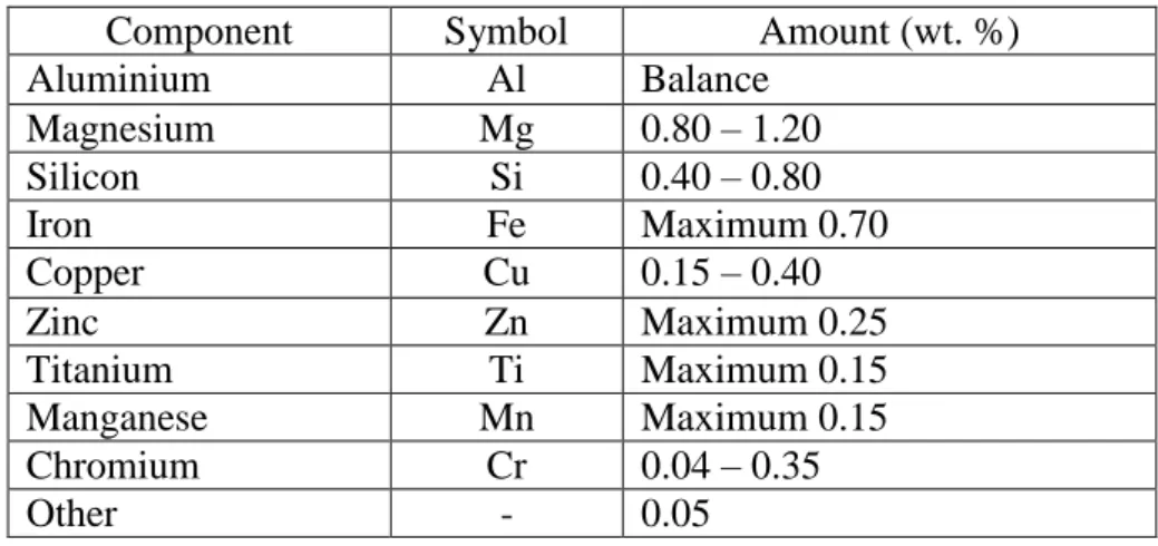
Component Symbol Amount (wt. %)
Aluminium Al Balance
Magnesium Mg 0.80 – 1.20
Silicon Si 0.40 – 0.80
Iron Fe Maximum 0.70
Copper Cu 0.15 – 0.40
Zinc Zn Maximum 0.25
Titanium Ti Maximum 0.15
Manganese Mn Maximum 0.15
Chromium Cr 0.04 – 0.35
Other - 0.05
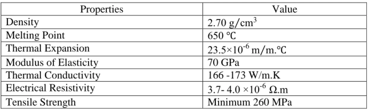
Properties Value
Density 2.70 g cm⁄ 3
Melting Point 650 ℃
Thermal Expansion 23.5×10⁻⁶m m.℃⁄
Modulus of Elasticity 70 GPa
Thermal Conductivity 166 -173 W/m.K
Electrical Resistivity 3.7- 4.0 ×10⁻⁶ Ω.m
Tensile Strength Minimum 260 MPa
TABLE 1. Composition of aluminium alloy 6061
TABLE 2. Mechanical properties of aluminium alloy 6061
6
2.3 GAS NITRIDING PROCESS ON ALUMINIUM ALLOY 6061
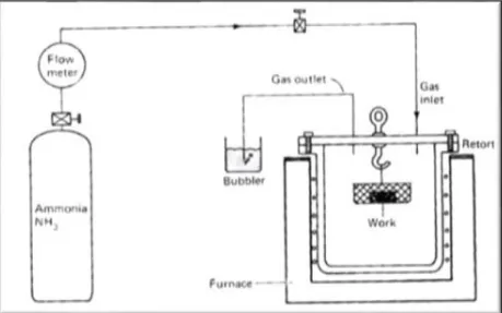
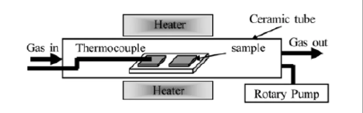
2.3.1 Conventional Nitriding Using Ammonia Gas as Nitrogen Donor In this method, the Aluminium is heated in the furnace with ammonia gas being flown into the furnace at temperature ranging from 500℃ to 590℃. This result with thermal chemical reaction of ammonia as its molecule decomposed into nascent nitrogen and hydrogen when it contact with hot surface metal as shown in the equation below [1].
2 NH3 → 2N + 3H2………(Eq.1)
Part of the nascent nitrogen created diffuses into the interior of the aluminium substrate and subsequently forming a nitrided case. The process is controlled by adjusting the flow rate of ammonia where dissociation rate for ammonia is between 15% to 30% for single stage nitriding and 75% to 80% dissociation rate for double stage nitriding [1].
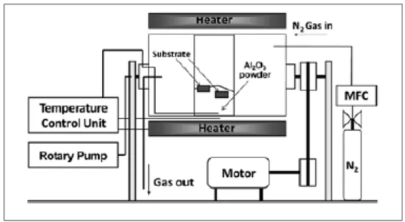
2.3.2 Barrel Nitriding and Standard Nitriding Using Pure Nitrogen As the name implied, this method used a barrel which is normally used for plating or as polishing is equipped where Alumina 𝐴𝑙2𝑂3 powders and Al-Mg alloy powder are made as the filling inside the barrel. The metal is heated and nitrided consecutively during the oscillating movement of the barrel tank. As the barrel swing, these 100 µm grain size powders flow will like a liquid while at the same time nitrogen gas is introduced within the flow rate ranging 0.2 L/min to 3.0 L/min under the
FIGURE 1. Gas nitriding process using ammonia
7
temperature 500℃ to 800℃. Whereas for the standard nitriding, there is no additional powders to react with the substrate and the metals only being exposed to the flowing nitrogen inside the furnace [6].
2.3.3 Nitrocarburizing Using Carbon and Nitrogen Gas
This process is a modified form of gas nitriding which is known as gas ferritic nitrocarburizing. In the process, nitrogen and carbon are simultaneously introduced into the steel while it is in the ferritic condition, that is at a temperature below which austenite begins to form during heating [10]. Nitrocarburizing atmospheres which typically performed at high temperature for about 570℃ exhibit more complex composition containing NH3, H2, CO, CO2 and H2O. This atmosphere containing NH3 and H2 gas components to initiate nitriding reaction as in equation 2 whereas CO and CO2 to establish carburizing reaction as in equation 3 [11].
FIGURE 2. Gas nitriding with pure nitrogen
FIGURE 3. Barrel nitriding
8
CO2+ H2 ↔ CO + H2O……...(Eq.2) CO + H2 → C + H2O…………(Eq.3)
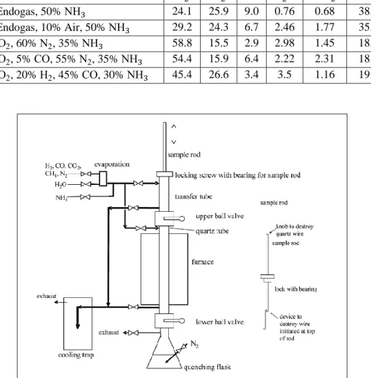
Hydrogen needed for this reaction originates from dissociated ammonia as in equation 1 or by separate addition of hydrogen. Carbon monoxide will formed as the product which then react with hydrogen to form carbon. Table 3 show the typical percent of gas mixture used in nitrocarburising process. Apart from CO2-H2-H2O reaction atmosphere or better known as heterogeneous water gas reaction, carburizing also can be achieved by exposing the specimen in a CH4-H2 atmosphere according to equation 4 below [12].
CH4 ↔ C + 2H2…………(Eq.4)
Added Gas Mixture Equilibrium Composition (vol%)
N2 H2 CO H2O CO2 NH3 50% Endogas, 50% NH3 24.1 25.9 9.0 0.76 0.68 38.4 40% Endogas, 10% Air, 50% NH3 29.2 24.3 6.7 2.46 1.77 35.4 5% CO2, 60% N2, 35% NH3 58.8 15.5 2.9 2.98 1.45 18.4 5% CO2, 5% CO, 55% N2, 35% NH3 54.4 15.9 6.4 2.22 2.31 18.6 5% CO2, 20% H2, 45% CO, 30% NH3 45.4 26.6 3.4 3.5 1.16 19.9
TABLE 3. Composition of gas mixture
FIGURE 4. Nitrocarburising process
9
2.3.3 Effects of Gas Nitriding on Aluminium
Nitriding the Aluminium to form nitride layer by nitrogen diffusion is very difficult as it has low solubility of nitrogen due to the formation of dense oxide film that exists on the surface. This layer keeps the dispersion of nitrogen into the aluminium substrate. Furthermore the formation of Al oxide occurs more readily than Aluminium Nitrate because of better affinity between Aluminium and oxygen in comparison with nitrogen. Therefore, the development rate of the aluminium nitride layer is extremely low [7].
Aluminium nitride is known for its high hardness about of HV1400 while normal aluminium only has hardness value around HV96 TO HV98 [8]. After the gas nitriding process was done, the aluminium surface will changed from metallic silver to dark grey or shiny black. The changing on the surface’s colour confirmed the formation of aluminium nitride layer on the vicinity of the surface after nitriding. It also exhibits good corrosion resistance, wear resistance, high electrical resistivity and high thermal conductivity which is 320 W/mK. Aluminium nitride has a hexagonal crystal structure and is a covalent bonded material and required lot of energy to break it [7].
10
CHAPTER 3 METHODOLOGY
3.1 SAMPLE PREPARATION
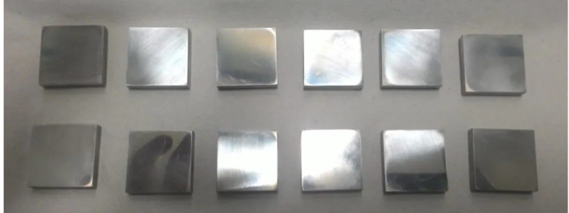
The sample 4” × 4” × 0.4” aluminium 6061 plate was cut using Electrical Discharge Machine (EDM) into 12 small 2 cm × 2 cm × 2 cm block, two for base reading and another 10 are for after nitriding reading. 5 pieces for 4 hours and the rest for 8 hours gas nitriding process.
Wire-Cut EDM was used which applied Computer Numerical Control (CNC) to produce specific shape and size on the material. The principle involves a continuous- traveling vertical wire with diameter as small as needle under tension where the path is controlled by the CNC to produce the shape required.
FIGURE 5. Sample cut into 12 small pieces
FIGURE 6. Cutting with EDM
11
All the samples then were grinded and polished to produce clean and smooth surface for even and strong coating. Grinding started with sand paper grit 180, 400, 600, 800 and lastly 1200. Then, the samples were polished using 6 micron diamond paste. All of these process use 300 rpm speed grinder and polisher. The final must be smooth, even and mirror-finish [9].
FIGURE 7. Grinding Process
FIGURE 1: KEPING FIGURE 8. Samples after polishing
12 3.2 GAS NITRIDING PROCESS
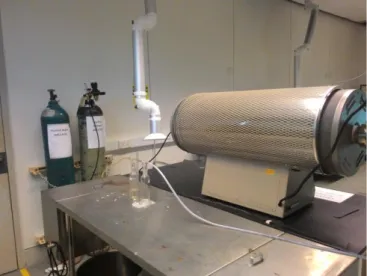
The samples were washed by immersing into 0.5M nitric acid for 3 minutes to remove oxide layer and other contaminants. Then, the samples were place on a tray and put inside the quartz tube furnace. The tube was closed, sealed and the furnace was turned on. The samples were pre-heat for about one and half hour with 10 cm3⁄min nitrogen gas flow inside the tube until the furnace reach desired temperature. The temperature will remain at 550℃ and samples were heated for 4 hours. The pressure inside the furnace is same as the atmosphere pressure. Once the process was done, the nitrogen gas was turned off when the furnace reaches room temperature. Then, the tube was opened and samples were taken out. All of these steps were same for 8 hours gas nitriding [9].
FIGURE 9. Gas nitriding equipment
FIGURE 10. Nitrogen tank
13 3.3 SECOND SAMPLE PREPARATION
A nitrided sample from each batch was cut into half using abrasive cutter. The half cut was mounted using hot mounting with the inner cross section as the top surface. Then, it was grinded using sand paper grit 180, 400, 600, 800 and 1200 followed by polishing using 6 micron diamond paste until the surface turn into mirror finished.
After completely cool, the mounted sample was washed using tap water to remove any debris followed by ethanol wash to remove excess water. The samples were left to dry inside the dryer. Then the sample is etched using Keller’s etchant by immersing the sample into it for 10 to 30 seconds. This is to make grain boundaries more visible under the microscope. Keller’s Etchant is a mixture of 190ml of distilled water, 5ml of nitric acid, 5ml of hydrochloric acid and 5ml of hydrofluoric acid.
Finally, the mounted sample was washed again using tap water followed by ethanol and left dried inside the dryer. The etching is successful when the mirror finish turns into matte once it dry.
FIGURE 11. Samples after mounting
14 3.4 MICROSTRUCTURE TEST
Two microstructure test were conducted using Optical Microscope (OM) and Scanning Electron Microscope (SEM). The etched sample was place inside the SEM.
Magnification started from 50X until 3000X. Measurement was done using the provided software tools and all images were saved in viewer software. The composition of the sample can be determined using the built in Energy Dispersive Spectroscopy (EDS) in the SEM. After the image can be seen clearly, the thickness of the nitrided layer was measured. The desired area was marked as inspection point for the EDS to determine the element present on it. The EDS software was ran and the result will come out in graph form. Highest peak in graph showed the highest percentage and the dominancy of the element in the marked area. Line scanning also was carried out to access the diffusion profile of nitrogen into the aluminium. The test also was viewed using OM to see the changes in the grain boundary between nitrided and unnitrided samples.
FIGURE 12. SEM equipment
15 3.5 HARDNESS TEST
The hardness test is conducted using the Rockwell Hardness machine with scale B following the ASTM E 18-2000 Standard. The load is 100kgf load with 1/16”
ball indenter. The dial measured the depth of the impression. From the value obtained, HRB reading measured can determine the hardness of the sample.
3.6 SCRATCH TEST
Scratch Test was done using the Revetest Scratch Test Machine. The test following the standard ASTM-G171 for scratch hardness of materials using a diamond stylus. The settings are 5N constant load, 5mm track length and 5mm/min speed. The scratcher is 200μm, 120° spherical diamond stylus. Each sample was scratched and the width track was measured at three points [9].
FIGURE 13. Rockwell hardness test scale B
FIGURE 14. CSM Revetest Scratch Test
16 3.7 PROCESS FLOW CHART
Comprehensive study on the literature review
Developing the experimental procedure 1. Gas Nitriding Process
2. Microstructure 3. Hardness Test 4. Scratch Test
Validation?
Preparing the sample
1. Cutting - according to the standard 2. Cleaning - grinding and polishing 3. Mounting - hot & cold mounting 4. Etching - Keller’s etchant
Carry out the experiment
Performing sample testing 1. Microstructure 2. Hardness Test 3. Scratch Test
Final report and technical paper progress YES
NO START
END
17 3.8 KEY MILESTONE
TASK COMPLETION DATE
Topic selection 1st October 2015
Submission of Extended Proposal 7th November 2015
Proposal Defense 3rd December 2015
Submission of Interim Report 31st December 2015
Material Shopping 31st January 2016
Sample Preparation 7th February 2016
Submission of Progress Report 6th March 2016
Gas Nitriding Process 3rd April 2016
Experimental Testing 10th April 2016
Submission of Interim Report and Technical Paper 17th April 2016 Final Year Project Presentation 24th April 2016
3.9 GANTT CHART Semester 1
Semester 2
Detail / Week 1 2 3 4 5 6 7 8 9 10 11 12 13 14 Selection of Project Topic Preliminary Research Work Extended Proposal
Experimental method study
Proposal Defense Interim Report Writing Interim Report Submission
Detail / Week 1 2 3 4 5 6 7 8 9 10 11 12 13 14 Material Shopping Sample Preparation Progress Report Gas Nitriding Process Experimental Testing Final Report writing Project Presentation
TABLE 5. Gantt chart for first semester TABLE 4. Key milestone of the project
TABLE 6. Gantt chart for second semester
18
CHAPTER 4
RESULTS AND DISCUSSION
4.1 RESULTS & DATA GATHERING 4.1.1 Gas Nitriding Results
Diffusing nitrogen gas into the surface of aluminium sample changes the appearance from shiny silvery to dark grey. The change of colour is due to the formation of black layer along the surface. As nitrogen gas was induced during heat treatment on aluminium, the nitrogen gas diffused into the aluminium surface and form aluminium nitride layer. As time increase, more nitrogen gas diffused and form aluminium nitride. This compound deposited on the aluminium surface became thicker and covered the entire surface. Layer become thicker and more visible. Aluminium has low solubility of nitrogen gas due to its FCC structure.
FIGURE 15 shows all the unnitrided samples after being grinded and polished.
It can be seen that the process produced mirror-like silvery surface on the samples.
Whereas on FIGURE 16 and FIGURE 17, the surfaces became dull grey proving nitriding had taken place.
FIGURE 15. Unnitrided samples
FIGURE 17. 8 hours nitrided Samples FIGURE 16. 4 hours nitrided Samples
19 4.1.2 Microstructure Results
From the microstructure test, results obtained from the SEM can be used to investigate the thickness of nitrided layer formed, element composition of the sample and diffusion pattern of the nitrogen from the gas nitriding process conducted.
FIGURE 18. SEM image of nitrided layer for 4 hours
FIGURE 19. SEM image of nitrided layer for 8 hours hours
20
Based on FIGURE 18 and FIGURE 19 above, it clearly can be seen that nitrided layer have formed on the sample surface. Light grey is the aluminium 6061 sample while thin, darker grey indicates the nitrided layer. Three points of
measurement for thickness were taken on the layer with the magnification 1500x.
Table below shows the thickness readings of the nitrided layer.
Thicknes 4 Hours Sample (μm) 8 Hours Sample (μm)
Reading 1 5.4 11.3
Reading 2 9.7 11.5
Reading 3 5.9 10.5
Average Reading 7.0 11.1
Line Scanning was conducted to identify the aluminium and nitrogen diffusion profile on the nitrided layer. Zebra dotted line in FIGURE 20 and FIGURE 21 below show the cross sectional line where the profiles were taken to see the diffusion pattern of nitrogen into aluminium sample surface.
FIGURE 20: Cross sectional line of nitrided layer for 4 hours TABLE 7. Thickness of nitrided layer
formed
21
FIGURE 22 and FIGURE 23 below display aluminium and nitrogen diffusion profile from the line scanning where orange line is the aluminium pattern and the blue line is the nitrogen diffusion pattern. On the region near the surface, nitrogen portion is high. However the pattern decreases as it goes to the core showing the amount of diffused nitrogen is lesser on the region near the sample core.
FIGURE 22. Line Scanning Profile of nitrided layer for 4 hours FIGURE 21. Cross sectional line of nitrided layer for 8 hours
22
As for the FIGURE 24 and FIGURE 25 below, the element composition of aluminium and nitrogen were shown from the region marked with black circle in FIGURE 19 and FIGURE 20. The marked region indicates the inspection point for the composition inspection. From the graph, it can be seen that the aluminium shows the highest peak since this element made up the alloy while the nitrogen is present although the amount is small. The presence of this two elements proved that the dark grey layer is aluminium nitride layer.
Element Number
Element Symbol
Element Name
Weight Concentration
13 Al Aluminium 98.8
7 N Nitrogen 1.2
FIGURE 24. Element composition on 4 hours nitrided sample
FIGURE 23. Line Scanning Profile of nitrided layer for 8 hours
23 Element
Number
Element Symbol
Element Name
Weight Concentration
13 Al Aluminium 97.9
7 N Nitrogen 2.1
FIGURE 25. Element composition on 8 hours nitrided sample
24 4.1.3 Hardness Results
Hardness is defined as resistance of material to plastic deformation caused by indentation. Hardness Rockwell scale B is used to determine the hardness of unnitrided and nitrided aluminium. The load in this scale is 100kgf with 1/16” ball indenter. Table below shows the hardness value for each samples.
Aluminium Sample Value 1 Value 2 Value 3 Average Value
Unnitrided 54 54 53 54
4 Hours Nitrided 34 33 32 33
8 Hours Nitrided 32 31 30 31
From Table 8 and FIGURE 26 above, hardness value from Rockwell test of both 4 hours nitrided and 8 hours nitrided samples are lower than the unnitrided sample.
Hardness obtained for 4 hours nitriding is HRB33 whereas 8 hours nitriding is HRB31.
These values showing decrement of 38% for 4 hours nitriding and 42% for 8 hours nitriding compared to the unnitrided hardness which has the value of HRB54.
0 10 20 30 40 50 60
Unnitrided 4 Hours Nitrided 8 Hours Nitrided Average Hardness Value
TABLE 8. HRB Reading
FIGURE 26. Average HRB Value with respect to exposure time of nitriding
25 4.1.4 Scratch Test Results
The test was conducted to measure the resistance of material surface to permanent deformation under the straight line motion of 200μm diamond stylus spherical scratcher with 5N constant load, 5mm track length and 5mm/min speed.
FIGURE 27. Scratch track on unnitrided sample
FIGURE 28. Penetration depth on unnitrided sample
26
FIGURE 27 shows the scratch track on unnitrided sample. The width of the track was measured at three points and the average width track for this sample is 282 μm. FIGURE 28 shows the graph for penetration depth on unitrided sample which is 4.2 μm. The red line represent the constant load of 5N that was applied along the process while the blue line is the acoustic emission indicating the sound of surface fractured.
FIGURE 29. Scratch track on 4 hours nitrided sample
FIGURE 30. Penetration depth on 4 hours nitrided sample
27
FIGURE 29 shows the scratch track on 4 hours nitrided sample. It can be observed that the width track is bigger compared to unnitrided sample with the average of 359 μm. FIGURE 30 shows the graph for penetration depth for the 4 hours sample’s scratch track. The penetration depth on this sample is 9.5 μm which is 55% deeper than the unnitrided sample.
FIGURE 31. Scratch track on 8 hours nitrided sample
FIGURE 32. Penetration depth on 8 hours nitrided sample
28
FIGURE 31 shows the scratch track on 8 hours nitrided sample. The width track is the biggest compared to unnitrided and 4 hours nitrided samples with the average of 593 μm. FIGURE 32 shows the graph for penetration depth for the 8 hours nitrided sample. The penetration depth is 10.7 μm which is 61% deeper than the unnitrided sample. Table 9 below shows the summary for the scratch tracks of all the three samples.
Aluminium Sample Width 1 (μm)
Width 2 (μm)
Width 3 (μm)
Average Width (μm)
Unnitrided 282 281 283 282
4 Hours Nitrided 359 359 358 359
8 Hours Nitrided 594 592 593 593
The average width of the scratch tracks measured is used to calculate scratch hardness number, HSp from the following formula:
𝐻𝑆𝑝= 8𝑃 𝜋𝑤2
Where P is the normal force applied and w is the average width track in meter.
Sample 𝐻𝑆𝑝 (GPa)
Unnitrided 0.16
4 Hours Nitrided 0.09 8 Hours Nitrided 0.03
Scratch hardness number cannot determine the exact wear rate value for the material. However HSp number can still be used to justify the wear resistance of compared samples. High HSp number means the sample has high wear resistance while low HSp number means low wear resistance held by the sample.
TABLE 10. Scratch Hardness Number TABLE 9. Width reading of the scratch tracks
29 4.2 DISCUSSION AND DATA ANALYSIS
From the microstructure results obtained, aluminium nitride, AlN layer formed proved the gas nitriding process was successful. Nitrogen gas, N2 have diffused into the aluminium surface as seen through SEM. Nevertheless, data gathering from the mechanical testing showed the contrary results. Instead of hardening the surface of aluminium 6061, it seem gas nitriding process conducted is softening the samples.
With reference to the literature, the hardness should be increase when nitriding with ammonia gas, NH3. However, for my project, only nitrogen gas N2 was applied.
Aluminium alloy has strong oxide layer, Al2O3 which prevent the N2 gas from diffusing into the surface metal. Injecting NH3 gas during the nitriding process will break down the ammonia molecule into the nitrogen and hydrogen atom when reacted with aluminium under heating. Thus the surface layer of Al with the formality of aluminium oxide Al2O3 prevented the diffusion of NH3 into the aluminium alloy.
When Al exposed to the atmosphere, Al2O3 was easily formed due to the oxidation.
When using NH3, the decomposition will reduce the oxide layer as the hydrogen will react with oxide to form water, hence diffusion of N2 will take place as in the equation below:
𝟐NH3+ Al2O3→ 2AlN + 3H2O
FIGURE 33. Decomposition of ammonia in gas nitriding
30
Lower scratch hardness number, HSp and Rockwell hardness number, HRB signify the lower hardness possess by the aluminium alloy after undergo the gas nitriding process. This is due to ageing process that occurred naturally after prolong heating at 550℃ for 4 hours and 8 hours left to cool in ambient temperature. Therefore from the microstructure analysis of using OM, the formation of grain growth can be analyzed. The grain growth affects the decrease in hardness. Prolong heating increase the diffusion rate of atom, in this case nitrogen atom which created the nitrided layer.
Nonetheless, this resulted in coarsening of the grains where the small grains dissolute and the big grains grew larger [13].
FIGURE 34 below shows the microstructures of the grain boundary for unitrided sample, 4 hours nitrided sample and 8 hours nitrided sample viewed using Optical Microscope. It can be observed that grain growth have occurred in nitriding samples as the grains grew larger than the unnitrided sample. Darker grains indicates the nitrogen have diffused into the grains structure.
This unexpected ageing causing the grains growth to occur which consequence to reducing the hardness but increasing ductility properties, making it more workable such as bending. It is found that this process worked similar to the annealing process where there is action of heating and cooling of material to increase the ductility while decreasing the hardness to make it easier to be workable for material fabrication.
50 μm
---
50 μm
---
FIGURE 34. Microstructures in all three samples: (a) unnitrided, (b) 4 hours nitrided, (c) 8 hours nitrided
50 μm
---
31
CHAPTER 5
CONCLUSION AND RECOMMENDATION
5.1 CONCLUSION
All Objectives were achieved. The gas nitriding was successfully conducted on aluminium 6061 at 550℃ for 4 hours and 8 hours. Observation on the sample surface changes from shiny silvery to dark grey indicates the nitride layer have formed. When viewed using SEM, the microstructure test confirmed the formation of aluminium nitride layer with the thickness of 7 μm in 4 hours nitrided sample and 11.1 μm in 8 hours nitrided sample. EDS will used X-ray emission to sort out the elements in a material and give a result in graph form. Aluminium nitride presence is indicated by high peak of aluminium and nitrogen when inspected using EDS. This graph will resulted in aluminium as the highest peak followed by nitrogen.
The HRB number from the Rockwell hardness test and scratch hardness number, HSp for both nitrided samples giving unexpected results as the average HRB and HSp for 4 hours nitrided are 33 and 0.09 GPa whereas HRB and HSp for 8 hours are 31 and 0.03 GPa respectively. These values are lower than the unnitrided sample which has the hardness value of HRB54 and HSp of 0.16 GPa. Lower hardness number in both Rockwell test and scratch test signify the change of mechanical properties at which hardness is reduced while ductility has increased. This explained by the occurrence of natural ageing process which resulted in grain growth in both nitrided samples as seen through Optical Microscope. This discovery could be the alternative method for annealing in reducing the hardness with increased ductility for working with material fabrication.
32 5.2 RECOMMENDATION
Sample preparation is very important before conducting the gas nitridning process and microstructure test. Sample must be ensured to have even, smooth and mirror finish from grinding and polishing process and conduct proper etching before analyse with OM or SEM so as to have clear view on the microstructure.
Ammonia gas, NH3 is more suitable to be used instead of pure nitrogen, N2 for gas nitriding on aluminium alloy since Aluminium has strong passive oxide film, Al2O3. The decomposition of ammonia to hydrogen and nitrogen will make the diffusion of nitrogen into the surface to take place easier as the hydrogen will react with the oxide on the aluminium and formed water. Yet, ammonia is an explosive gas which need to be handled carefully.
Since the nitrided layer formed is in micron scale, Micro Vickers Hardness is more compatible choice to carry out the hardness testing. This is because Micro Vickers is measured as HV number which indicates values in micron scale. Compared to Rockwell Hardness B-scale, Micro Vickers Testing can determine the hardness of the nitrided layer formed without deforming of damaging the sample surface.
Wear resistance indicates by the wear rate number must be determined using the correct wear test. This can be done by using ASTM standard such as Pin-On-Disk Test (ASTM G99) or conducting Wet Sand/Rubber Wheel Abrasion Tests (G195).
33
REFERENCES
[1] P. Weymer, "Principles of Gas Nitriding," Heat Treating Progress, pp. 12-13, 2009.
[2] “Chapter 1: An Introduction to Nitriding," Practical Nitriding and Ferritic Nitrocarburizing, pp. 1-12, 2003.
[3] D. Kent, G. B. Schaffer, T. B. Sercombe, and J. Drennan, "A novel method for the production of aluminium nitride," Scripta Materialia, vol. 54, pp. 2125-2129, 6// 2006.
[4] "Aluminium 6061 - T6 Extrusion," aalco, [Online]. Available:
http://www.aalco.co.uk/datasheets/Aluminium-Alloy-6061-T6- Extrusions_145.ashx. [Accessed 27 October 2015].
[5] J. Ho, “A Discussion on Material Choices in Mobile”, Anandtech.com, 2015.
[Online]. Available: http://www.anandtech.com/show/7984/discussion-on- material-choices-in-mobile. [Accessed: 02- Nov- 2015].
[6] M. Yoshida, R. Ichiki, and N. Utsumi, "Surface hardening of titanium using gas nitriding," International Journal of Precision Engineering and Manufacturing, vol.
14, pp. 971-976, 2013/06/01 2013.
[7] M. Okumiya, Y. Tsunekawa, H. Sugiyama, Y. Tanaka, N. Takano, and M.
Tomimoto, "Surface modification of aluminum using ion nitriding and barrel nitriding," Surface and Coatings Technology, vol. 200, pp. 35-39, 10/1/ 2005.
[8] S. Gredelj, A. R. Gerson, S. Kumar, and N. S. McIntyre, "Plasma nitriding and in situ characterisation of aluminium," Applied Surface Science, vol. 199, pp. 234- 247, 10/30/ 2002.
[9] J. Juhalin, "A Study on the Effects of Gas Nitriding on Aluminium 6061 for Automotive Cylinder Application," Tronoh, Perak, 2014.
[10]J. R. Davis, Surface Hardening of Steels, Ohio, United States of America: ASM International, 2002.
[11] T. Holm, L. Sproge "Nitriding and Nitrocarburizing" Furnace Atmosphere 3, Sweden.
[12]J. Dossett and G.E. Totten,"Fundamental of Nitriding and
Nitrocarburizing,"Steel Heat Treating and Processes, vol. 4A, ASM International, 2013
[13] N. Wang, Z. Zhou, G. Lu, “Microstructural Evolution of 6061 Alloy during Isothermal Heat Treatment", vol. 27, p.p 8-14, Shenyang, China. Retrieved on 1/1/ 2010 from www.sciencedirect.com.