In the construction industry, FRP contributes a lot because it can improve the strength of structures. The use of FRP is agreed as one of the value for money alternatives as it can improve the strength of structures (Hollaway & Leeming, 1999). Therefore, most of the design will include the presence of internal steel reinforcement and external fiber-reinforced polymer.
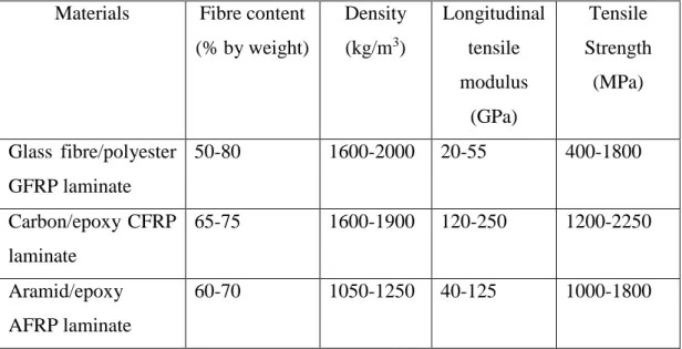
Thus, the effectiveness of externally bonded FRP as one of the strengthened members is still controversial. FRP has become one of the famous components to be used in the construction industry to increase the strength of reinforced concrete Khalifa, Gold, Nanni and MI (1998). The properties of FRP and the materials used in FRP are discussed in one of the important codes which is ACI 440R-96 (Taha & Shrive, 2003).
One of the parameters that is still questionable is the interaction between internal steel braces and externally bonded FRP (Mofidi & Chaallal, 2014a). Due to the increases in FRP spacing, the post-cracking stiffness will be reduced due to the ineffective beam confinement (Panchacharam & Belarbi, 2002). This will be followed by tensile failure of the FRP before the crushing of the concrete.
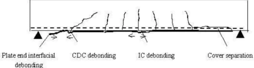
Based on previous research, the majority of failures of beams retrofitted by U-jackets failed due to fracture.
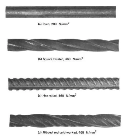
STEEL REINFORCEMENT
One of the codes used for design states that internal steel reinforcement should be between 0.75d and 300mm, but this is sometimes not applicable as it can be changed for effectiveness. In contrast, the other UK Concrete Society code states that internal reinforcement should be within the range of 0.8d and Wfrp + d/4 (Arya, Clarke, Kay, & O'Regan, 2002). The use of additional transverse steel in the beam to support the shear resulted in less influence of FRP on the shear resistance (Bousselham & Chaallal, 2008).
Therefore, steel is very important in the construction industry to overcome shear failure of structures.
BOND BEHAVIOUR
To achieve the aim of this project, it will only cover factor (f) which is due to the loading of the samples. Bond between FRP and beams will be affected by the potential of FRP to transfer stresses to those beams. Steel reinforcement ratio has a huge impact on the shear resistance of RC beams (Joint ACI-ASCE Committee 445 1998; CEN 1991).
The use of FRP for structural damage repair is emerging as an efficient and effective practice for returning and improving the strength of RC members. Most of the approved and reliable method used recently is for members strengthened in bending. However, there is a lack of research investigated on the relationship between width and distance between applied FRP and T-beam and shear reinforcement ratio, which is between internal reinforcement and external FRP.
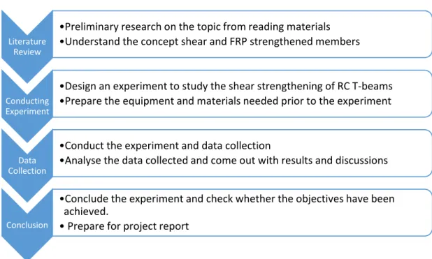
During this phase, the required experiment will be designed by preparing the equipment and materials for that experiment. Based on the experiment, data will be collected and analyzed before concluding and writing the report.
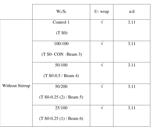
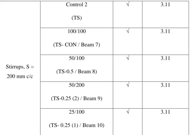
Experimental Program Description of specimens
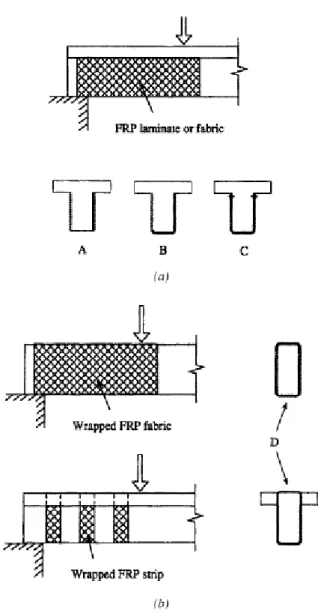
Beams without stirrups are labeled as T S0, while all beams with stirrups are labeled as TS. To check the effectiveness of FRP, the width and distance between FRP has been used differently. Care has been taken to ensure that all beams used in this experimental program follow these standard dimensions, as shown in the diagram above.
This is very important to get a good result and to be able to compare. In addition, the position of FRP and steel braces for each beam is set up as in the figures below:.
Materials and Methods
Process Flow of Experiment
Key Milestone
Gantt Chart
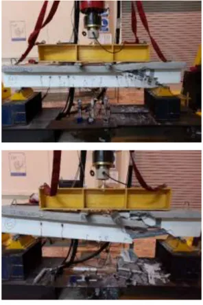
We have observed the collapse of beams with different ratio of shear reinforcement and in the presence and absence of stirrups. In this study, only a test was conducted to determine the effect of internal steel stirrups and external bonded FRP and the effect of shear reinforcement ratio. A correlation was also found between the presence of stirrups and the ratio of shear reinforcement to strength.
The shear strength of all samples and the type of fracture are obtained during the experiment. Steel braces will resist shear better than externally bonded FRP, which will cause less contribution from FRP (Bousselham & Chaallal, 2008). For two of the beams with braces, TS-0.5 and TS-CON, the loss of strength is visible because both beams were dropped before the test.
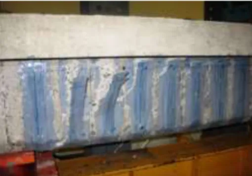
Besides that, as a result of this experimental result, continuous wrap of U-wrap FRP for beam without stirrups gains much strength in the presence of FRP which is 56.7 percent. Deflection of the specimens with respect to the applied load is very important to be determined. T S0-CON which is the continuous wrap of FRP can have higher load during that length of deflection.
Both samples are expected to be among the highest scores since these beams are continuously wrapped and use a large amount of FRP. As for this plot, the comparison must ignore the result of TS-CON and TS-0.5 (1) beams in order to get a conclusion because there is a sampling error. The deformation of each beam is different from each other because it was determined based on the propagation and interference of the defect.
As a conclusion of this project, the presence of beams shows better performance compared to specimens without beams. From this experiment it is clearly seen that the shear reinforcement is inversely proportional to the FRP contribution. It is recommended to ensure that the strength of the concrete used is standardized for all specimens.
Paper presented at the Proceedings of the 2nd International Conference on Advanced Composite Materials in Bridges and Structures, Acmbs-Ii, Montreal 1996. Effect of steel braces on shear resistance gain due to externally bonded fiber reinforced polymer strips and plates.