The Consistency of Relational Database and Object-Relational Database in GIS Applications
by
Siti Nadiah AlSadat Bt Shuklcran Hilmi AlSadat
Dissertation submitted in partial fulfillment of the requirement for the
Bachelor Of Technology (Hons) (Information System)
JUNE 2004
Universiti Teknologi PETRONAS
Bandar Seri Iskandar 31750 Tronoh Perak Darul Ridzuan
&
•Sto
•X&& Li
2, {T(l? -tUii?,
^ ^ - ^
CERTIFICATION OF APPROVAL
The Consistency of Relational Database and Object-Relational Database in GIS Applications
Approved by,
by
Siti Nadiah AlSadat Bt Shukkran Hilmi AlSadat
A project dissertation submitted to the Information System Programme Universiti Teknologi PETRONAS In partial fulfillment of the requirement for the
BACHELOR OF TECHNOLOGY (Hons) (INFORMATION SYSTEM)
(Mr. Justin Dinesh Devaraj)
UNIVERSITI TEKNOLOGI PETRONAS
TRONOH, PERAK
JUNE 2004
CERTIFICATION OF ORIGINALITY
This is to certify that I am responsible for the work submitted in this project, that the original work is my own except as specified in the references and acknowledgements, and that the original work contained herein have not been undertaken or done by unspecified sources or persons.
SITI NADIAH ALSADAT BT. SHUKKRAN HILMI ALSADAT
11
ABSTRACT
This final year project involves a research and a simple Geographical Information System (GIS) application that will show GIS, spatial data, spatial database management, which focused on relational and object-relational database management system. The main objectives of this project is to study and gain deeper understanding on the implementation of the two types of databases in GIS applications, to compare the level of performance between the databases in a GIS application and to determine the most suggested database to be implemented in a GIS application. The scope of the study will focus on integrating a GIS application that implements Malacca spatial database with two different database management system, namely relational database and object- relational database system. The performance of each database system will be identified and compared. Rapid Development environment methodology will be utilized in the research on the performance of relational and object-relational databases in GIS applications and also in the development of an application that will implement the database with GIS applications. This methodology basically involved overlapping Planning, Analysis, Design and Implementation phases. Database development design process involved conceptual, logical and physical design stages. This report also includes discussions on the consistency of relational database as well as of the object- relational database in GIS applications. This report suggests GIS application developer to choose object-relational database in order to manage both spatial and attributes data
for the applications efficiently. Furthermore, the result from the object-relational
database will be more consistent and reliable compared to a relational database and the performance is better. Recommendations for continuing this project are to compare and determine the level of consistency between relational database and object-relational database in World Wide Web environment or with multi-user accessing the database concurrently in order to study on the effects to the level of consistency and also to develop a map query interface.111
ACKNOWLEDGEMENTS
Heartfelt thanks to ALLAH God Almighty, that finally I have fulfilled my Final Year Project. Hereby, I would like to take this opportunity to convey my greatest appreciation to all the people who have been very cooperative and supportive to me during the accomplishment of this Final Year Project.
First of all, I would like to thanks Universiti Teknologi Petronas for arranging such beneficial course for the students, which will expose and enhance students' skills in the process of applying knowledge, expanding thoughts, solving problem independently and presenting findings. Besides, I would like to thank all of the FYP Committee members who have approved my Final Year Project tile and for managing this course proficiently.
I also would like to give my greatest gratitude to my Final Year Project Supervisor, Mr.
Justin Dinesh Devaraj who has been supervised and guided me in the accomplishment of this final year project. He is a very nice person and will not hesitate to give his cooperation to me throughout the development of this project.
Last but not least, I would like to give my special thanks to my parents and friends who had given me their moral support and undivided encouragement to complete this Final Year Project successfully. Thank you so much.
IV
TABLE OF CONTENTS
CERTIFICATION OF APPROVAL i
CERTIFICATION OF ORIGINALITY ii
ABSTRACT iii
ACKNOWLEDGEMENTS iv
TABLE OF CONTENTS v
LIST OF FIGURES vii
LIST OF TABLES viii
ABBREVIATIONS AND NOMENCLATURES ix
CHAPTER 1: INTRODUCTION 1
1.1 Background of Study 1
1.2 Problem Statement 5
1.2.1 Problem Identification 5
1.2.2 Significant of the Project 6
1.3 Objectives and Scope of Study 7
CHAPTER 2: LITERATURE RIVIEW AND THEORY 8 2.1 Components of a Geographic Information System 8
2.1.1 People 8
2.1.2 Data 9
2.1.3 Hardware 11
2.1.4 Software 11
2.1.5 Procedures 11
2.2 Database Management System in GIS 12 2.2.1 Hierarchical Database System 15
2.2.2 Network Database System 15
2.2.3 Relational Database System 16 2.2.4 Object Oriented Database System 16 2.2.5 Object-Relational Database System 17
2.3 Consistency in GIS Database 17
CHAPTER3: METHODOLOGY 20
3.1 Rapid Application Development 20
3.2 Database Development 21
3.2.1 Planning 21
3.2.2 Analysis 21
3.2.3 Three-Steps Database Design 22
3.2.4 Implementation 24
3.3 Tools Required 26
CHAPTER 4: RESULTS AND DISCUSSION 28
4.1 Discussions on Consistency of Relational Database 28 4.2 Discussions on Consistency of Network Database 33
CHAPTER 5: CONCLUSION AND RECOMMENDATION 37
REFERENCES 39
APPENDICES 43
APPENDIX 1 FYP GANTT CHART 44
APPENDIX 2 A comparison of DatabaseManagement System [31] 46 APPENDIX 3 Map data stored in a hierarchical database system 48 APPENDIX 4 The storage structure in a network-based database system. 49
APPENDIX 5 A relations database 50
APPENDIX 6 A Life Cycle of a GIS database 51
APPENDIX 7 ERD for Sample data, Canada Spatial Database 52 APPENDIX 8 ERD for State of Malacca 53
APPENDIX 9 ER diagram for the State of Malacca, with pictograms 54 APPENDIX 10 ERD for the State of Malacca after translated 55
into a Relational Database
APPENDIX 11 UML Class Diagram for the State of Malacca 56
v i
Figure 1.1 Figure 2.2 Figure 3.1
Figure 3.2.3 Figure 3.2.4
Figure 4.1.1
Figure 4.1.2 Figure 4.1.3
Figure 4.1.4
Figure 4.2.1
Figure 4.2.2
LIST OF FIGURES
Evolution of Databases 3
Evolution of Data Models 14
Sashimi Model with Four Basic Stages of a 21
Traditional Waterfall Model
Logical Design Compared with Physical Design 24 The Graphical User Interface of the State of. 25 Malacca Application
Result shown for the selected spatial queries from 29 MySQL relational database.
District table attributes from MySQL database 30 Result of the entered search for an admin body, which 30 is Beringin in relational database.
Query Result for "Admin-Body in 32
Melaka Tengah District".
Result shown for the selected spatial queries from 34 Oracle object-relational database.
Result of the entered search for an admin body, which is.... 34 Beringin in object-relational database.
v n
LIST OF TABLES
Table 1.1 Database systems and characteristics 4
Table 3.3 List of raw data requirements, hardware requirements 27 and software requirement for this project
Table 4.2a. Relational Database Vs. Object-Relational Database 35 Table 4.2b Types of application suitable for Relational 36
and Object-Relational Database.
v n i
ABBREVIATIONS AND NOMENCLATURES
CAD : computer added design
ESRI : Environmental Systems Research Institute GIS : geographic information system
ODBC : open database connectivity OLE : object linking and embedding
OODBMS : object oriented database management system ORDBMS : object relational database management system RAD : rapid application development
RDBMS : relational database management system SQL : structured query language
IX
CHAPTER 1 INTRODUCTION
1. INTRODUCTION
This chapter features the basic information of the project, which includes the background of the project, problem statement, the objectives and scope of the study.
Characteristics of different type of database systems and the comparison between the databases have been explained briefly. This project will be concentrating on two
different types of database systems that include Relational Database and Object-
Relational Database System implemented in GIS applications.1.1 Background Study
A database is a comprehensive collection of related data stored in logical files and collectively processed, usually in tabular form. In Geographic Information System (GIS) Applications, the database is the most important asset and the backbone for all digital and hard copy map production. Database Management Systems (DBMS) have beendeveloped to manipulate data such as imports, store, and sort and retrieve data in a
database.
There are three basic types of database that should be familiar in GIS, which are
hierarchical data structure, network systems and relational data structure. Of these threetypes of database systems, the hierarchical is the fastest but the most restrictive for the
user. This system is appropriate if the information can be naturally organized in the
database into the same structure as a hierarchy chart. The network system is more flexible than the hierarchical system but it is more difficult for a user than the relational
database system. The relational system is rapidly becoming the most popular of the
three. It is the most flexible and easiest to use. But this flexibility comes at the cost oflow speed compared to other database system. A part from these, flat-file database and object-oriented database management system (OODBMS) also have been used for GIS.
Table 1.1 shows the summaryof each of the Database systems and its characteristics.
The debate between relational versus object-oriented within the database community
parallels debate between vector versus raster in GISs. The introduction of abstract data types (ADTs) clearly adds flexibility to a DBMS, but there are two constraints peculiar
to databases that need to be resolved before ADTs can be fully integrated into DBMSs.These includes market adoption of OODBMS products has been limited, despite the
availability of such products for several years. This reduces the financial resources and engineering efforts to performance-tune OODBMS products. As a result, many GIS users will use systems other than OODBMS to manage their spatial data in the near future [1]. Besides, SQL is the lingua franca of the database world, and it is tightly coupled with the relational database model. SQL is a declarative language, that is, the
user only specifies the desired result rather than the means of production.Recently, a new technology has evolved in which relational and object-oriented concepts have been combined or merged. These systems are called object-relational
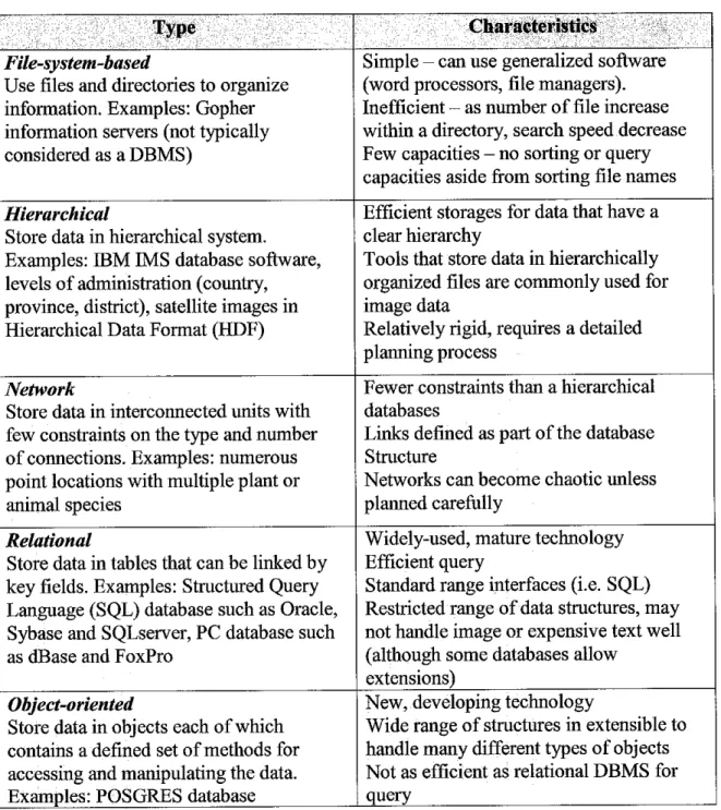
database systems (ORDBMS). It is a relational database that incorporates ADTs andother principles of object-oriented design. The main advantages of ORDBMS are
massive scalability and support for object-oriented features. Figure 1.1 shows theevolution of databases.
Among other technical issues in GIS, data quality is perhaps the most important as it
affects the ways in which the spatial data can be used and interpreted. Data quality
factors that pertain to the individual data elements include components such as
positional accuracy, attribute accuracy, logical consistency and resolution. GIS users at
all levels must be able to share current, accurate, and consistent geographic data quickly and efficiently in order to prepare for coordinate effective responses and to make decisions that will protect life and property. However, all spatial data is inaccurate to
some degree but it is generally represented in the computer to high precision. Thus, GIS application's developer need to consider the level of efficiency and consistency of the digital structures that represent the real world and also the algorithms that will compute
the true values of the products.
Network DBMS
Object-Oriented Systems (OODBMS)
File Systems
Relational DBMS
Object-Relational
ORDBMS
Hierarchical DBMS
Figure 1.1. Evolution of databases [1].
•;'--V/./ :",=;, :;";•'
CharacteristicsFile-system-based
Use files and directories to organize information. Examples: Gopher information servers (not typically considered as a DBMS)
Simple - can use generalized software (word processors, file managers).
Inefficient - as number of file increase
within a directory, search speed decrease Few capacities - no sorting or query capacities aside from sorting file names
Hierarchical
Store data in hierarchical system.
Examples: IBM IMS database software, levels of administration (country, province, district), satellite images in Hierarchical Data Format (HDF)
Efficient storages for data that have a clear hierarchy
Tools that store data in hierarchically organized files are commonly used for image data
Relatively rigid, requires a detailed planning process
Network
Store data in interconnected units with
few constraints on the type and number of connections. Examples: numerous point locations with multiple plant or animal species
Fewer constraints than a hierarchical databases
Links defined as part of the database
Structure
Networks can become chaotic unless
planned carefully
Relational
Store data in tables that can be linked by key fields. Examples: Structured Query Language (SQL) database such as Oracle, Sybase and SQLServer, PC database such
as dBase and FoxPro
Widely-used, mature technology Efficient query
Standard range interfaces (i.e. SQL) Restricted range of data structures, may not handle image or expensive text well (although some databases allow
extensions) Object-oriented
Store data in objects each of which
contains a defined set of methods for
accessing and manipulating the data.
Examples: POSGRES database
New, developing technology
Wide range of structures in extensible to handle many different types of objects
Not as efficient as relational DBMS for query
Table 1.1 Database systems and characteristics
1.2 Problem Statement
1.2.1 Problem Identification
Almost any serious Geographic Information System (GIS) application is based on a database system (mostly a relational one), and it is now considered a serious drawback
if a GIS is not connected to a database system. 60 percent of the cost of installing a GIS involves the development of the necessary database. Data costs are estimated may runinto several times the system costs over the life of a spatial information system [2].
Furthermore, Geographic Information System (GIS) applications usually involve a large-scale data usage especially geographic data, as it is always being referred to any combination of computer hardware and software, which is used for spatial analysis. GIS applications may range from a simple atlas program on a single user personal computer to a complex integration of spreadsheet, database, and GIS software operated on a
network, which may serve several dozen users, or more.GIS is indeed a powerful analytical tool, be it on a basic or complex level and it is now no longer very helpful for the users but it is required. Although GIS has many benefits, users must be aware of the problems that can arise, e.g. data inconsistency and erroneous spatial definitions. Knowing the limitations will help in providing results that are meaningful and accurate [3]. This is because, data inconsistency in GIS applications may lead to unreliable, inefficient and inaccurate data and decision-making.
Therefore, geographic databases are needed in order to ensure reliable and consistent data and also to integrate set of geographic data for a particular area and subject.
Besides, the geographic database is a critical part of an operational GIS application as it
involves the cost of creation and maintenance, and because of the impact of a
geographic database on all analysis, modeling, and decision-making activities.
Thus, it will be an advantage for a GIS application developer to know which database
approach is the most reliable approach to be implemented in a GIS application.
Consequently, a very high quality GIS application can be produced effectively and
efficiently.1.2.2 Significant of the Project
Relational database is the most popular model for GIS. The widely used relational
database software includes INFO in ARC/INFO, DBASE III for several PC-based GIS and ORACLE for several GIS uses. The relational database model is the most widelyaccepted for managing the attributes of geographic data. It is attractive because of its simplicity in organization and data modeling, flexibility where data can be manipulated in an ad hoc manner by joining tables and efficiency of storage by the proper design of
data tables redundant can be minimized.
Oracle8 and Oracle9i spatial are examples of ORDBMS introduced by the Oracle Corporation. Similar products are available from other database companies such as IBM. Appendix 2 shows a comparison of database systems.
Therefore, the implementation of these two types of database, namely relational and object-relational database system in GIS applications need to be studied and the performance of these databases need to be compared. This is in order to help GIS application developers and users to obtain a very high quality and reliable data, result, report and decision-making resulted from the GIS applications. Moreover, this study will also help to determine which database system is more efficient and reliable to be integrated with GIS applications. Besides, an efficient GIS application does not need to be only a flexible and easy to use database system but also a very reliable and consistent
database system.
1.3 Objectives and Scope of Study
This project is divided to two phases. In the first phase, the concept of Relational Database and Object-Relational Database is to be studied in detail as well as the performance of these databases in GIS applications particularly. In second phase, the design and implementation of the concept will be developed. This includes an attractive application that will enable users to view spatial data with different data model implemented in its database and performs spatial queries.
The objectives and scope of work to be achieved in thisproject are as follows:
i. To study the concepts of Relational Database and Object-Relational Database in
order to understand the differences of the database's design and implementation in GIS application.
ii. The same spatial data will be used in the design and development of both
relational database and object-relational database.iii. The spatial data that willbe used in this project is State of Malacca data.
iv. To design and implement an attractive application that will integrate the State of Malacca spatial data with the Relational and Object-Relational Database by using visual programming and applying proper user interface design.
v. To compare the performance of the databases and determine the most suggested
database to be implemented in a GIS application based on the research findings.
CHAPTER 2
LITERATURE REVIEW AND THEORY
2. LITERATURE RIVIEW AND THEORY
This chapter features a smaller and more focused scope on differences between data models, elements of consistency in GIS and the important of database consistency in GIS applications. It provides the background information on the level of consistency of different databases with different data models in GIS applications. This chapter also contains related findings on this field, consisting of relevant theories, hypotheses, facts and data, which are relevant to the objectives and the findings of the project.
2.1 Components of a Geographic Information System
A GIS can be divided into five components: People, Data, Hardware, Software, and Procedures. All of these components need to be in balance for the system to be successful. No one part can run without the other [3].
2.1.1 People
The people are the component who actually makes the GIS work. They include a plethora of positions including GIS managers, database administrator, application specialist, system analysts, and programmers. They are responsible for maintenance of
the geographic database and provide technical support.
People also need to be educated to make decisions on what type of system to use.
People associated with a GIS can be categorized into viewers, general users, and GIS
specialist.2.1.2 Data
Perhaps the most time consuming and costly aspect of initiating a GIS is creating a database. There are several things to consider before acquiring geographic data, it is crucial to check the quality of the databefore obtaining it. Errors in the data set can add many unpleasant and costly hours to implementing a GIS and the result and conclusions of the GIS analysis most likely to be wrong. Several guidelines to look at include:
i. Lineage
This is a description of the source material from which data were derived, and the
methods of derivation, including all transformations involved in producing the finaldigital files. This should include all dates of source material and updates and changes
made to it [4].
ii. Positional Accuracy
This is the closeness of an entity in an appropriate coordinate system to that entity's true
position in the system. The positional accuracy includes measures of the horizontal and
vertical accuracy of the features in the data set [5].
iii. Attribute Accuracy
An attribute is a fact about some location, set of locations, or features on the surface of the earth. This information often includes measurements of some sort, such as
temperature or elevation or a label of a place name. The source of error usually lies
within the collection of these facts. It is vital to the analysis aspects of a GIS that this
information be accurate.
iv. Logical Consistency
Logical consistency refers to the internal consistency of the data structure. A spatial data set is logically consistent when it complies with the structural characteristics of the data model and is compatible with attribute constraints [6]. It deals with the logical
rules of structure and attribute rules for spatial data and describes the compatibility of a datum with other data in a data set. There are several different mathematical theories and models used to test logical consistency such as metric and incidence tests,topological and order related tests. These consistency checks should be run at different
stages in the handling of spatial data [5].The tests should be performed in order to check on the compatible datum, valid attribute values and also the compatibility with the data model. Thus, the inconsistencies that
violates rules constraints such as in attribute range, geometric and topologicalconstraints and rules for spatial relationships and application can be reduced or
minimized. This shows that consistency is needed in order to control the operational transactions in GIS application.v. Completeness
This is a check to see if relevant data is missing with regards to the features and the attributes. This could deal with either omission errors or spatial rules such as minimum width or area that may limit the information [5] [7].
10
2.1.3 Hardware
Hardware consists of the technical equipment needed to run a GIS including a computer system with enough power to run the software, enough memory to store large amounts of data, and input and output devices such as scanners, digitizers, GPS data loggers, media disks, and printers [8].
2.1.4 Software
There are many different GIS software packages available today. All packages must be capable of data input, storage, management, transformation, analysis, and output, but the appearance, methods, resources, and ease of use of the various systems may be very different. Today's software packages are capable of allowing both graphical and descriptive data to be stored in a single database, known as the object-relational model.
Before this innovation, the geo-relational model was used. In this model, graphical and descriptive data sets were handled separately. The modern packages usually come with
a set of tools that can be customized to the users need.
2.1.5 Procedures
Procedures include how the data will be retrieved, input into the system, stored, managed, transformed, analyzed, and finally presented in a final output. The procedures are the steps taken to answer the question need to be resolved. The ability of a GIS to perform spatial analysis and answer these questions is what differentiates this type of system from any other information systems. The transformation processes includes such tasks as adjusting the coordinate system, setting a projection, correcting any digitized errors in a data set, and converting data from vector to raster or raster to vector [8].
11
2.2 Database Management System in GIS
Spatial databases apply to geometric points and links, such as those that in a Geographic Information System (GIS) or a Computer-Aided Design (CAD). Geometrical property relationships included in spatial database are metric relations, order, adjacency and
connectivity [9].
The spatial database is more complex than the conventional ones. It handles complex data types and relationships, voluminous information, potential real-time access along with questioning, and different levels of granularity for similar kinds of data. This database may handle geometric data in like segments and closed polygons represented
usually as x, y coordinates of its end points.In the geographic databases stream data conceptual models were regarded as a central
concern in future research. The data models in a standard data base environment were
perceived to be inefficient for handling geographic information. For example, quality cannot be attached to entities as quality information as these models only recognize them as attributes. Computer science developments presented a number of challenges for researchers with respect to data capture, data handling, data processing and data
exploitation [10].A distinction must be made between model and cartographic generalization. The difference between the cartographic and the model view is the possibility in the latter
case for database manipulation independent from graphic representation. Spatial objects may need to have multiple digital representations in which internal representations (models) should be distinguished from visualization (cartographic) representations.
Model generalization may be driven by analytical queries (where are the trends, what is the spatial average etc.) whereas cartographic generalization is mainly driven by communication requirements (legibility, graphical clarity). Another issue is the prioritization of topological relations between spatial objects, knowing that some
12
topological relations may be affected by generalization. Finally, an additional issue of model-oriented generalization was raised in the temporal domain [10].
A database management system (DBMS) provides a number of functions to create, edit, manipulate and analyze spatial and non-spatial data in the applications of a GIS. Major
functions of a database includes creating records of various data types such as integer,real, character, data, image etc., operations such as sort, delete, edit, select etc., manipulation such as input, analysis, output, reformatting etc., query which will be made by a standardized language such as SQL (Standard Query Language), programming which will very useful for application programs and documentation which includes metadata or descriptions of the contents of the database should be compiled.
A separate data model is used to store and maintain attribute data for GIS software. These data models may exist internally within the GIS software, or may be
reflected in external commercial Database Management Software (DBMS). Basically,there are four types of database models, which include hierarchical model, network model, relational model, and object-oriented model. Although all four types are used, as being mentioned previously in this report, the relational model has been the most successful in GIS. For example, some well known databases include dBase, Oracle and
Info. There has been debate on which the two-layers or object oriented is efficient inGIS. Layers may be efficient for natural resources management, for example with different layers of land use, soil, geology, agriculture and forest. On the other hand, object orientation may be more convenient for facility management with grouped
attributes.
Many data models have been proposed, which can categorize according to the types of concepts they use to describe the database structure [11]. The author also categorized the data models into three categories, which includes the high level and low level and the class of representational data models. The high level is the conceptual data model that provides concepts that are close to way many users perceive data. It uses concepts such as entities, attributes and relationships. Whereas the low level, which is the
13
physical data models, provide concepts that describe the details of how data is stored in the computer. Concepts provided by lo level data models are generally meant for computer specialists, not for typical end user. Between these two data models is a class of representational or implementation data models, which provide concepts that may be understood by end user but that, are nottoo far removed from the way data is organized within the computer. These models hide some details of data storage but can be implemented on a computer system in a direct way. It is also the model that is most frequently used in traditional commercial DBMS. The models represent data by using
record structures and hence are sometimes called record-based data models.
This means that a data model is a plan for building a database. The model represents
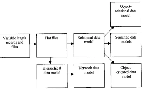
data conceptually, the way the user sees it, rather than how computers store it. Data models focus on required data elements and associations, most often they are expressed graphically using entity-relationship diagrams. On a more abstract level, the term is also used in describing a database's overall structure for example, hierarchical, relational and network data model. Historically, the hierarchical model was implemented first,
then the network model, then the relational model and flat models reached their zeniths.Object- relational data
model
/
*
Variable length records and
files
Flat files -•
Relational data model
-•
\
Semantic data models
i
\*Hierarchical data model
-•
Network data model
Object- oriented data
model
Figure 2.2: Evolution of DataModels
14
2.2.1 Hierarchical Database System
A hierarchical database system is one in which the DBMS supports a hierarchical structure of records organized in files at various logical levels with connections between the levels. Appendix 3 shows the map data stored in a hierarchical database system.
Hierarchical database systems are easily expanded ad updated. However, they require large index files, must be frequently maintained and are susceptible to multiple entries.
The advantages of hierarchical model are high speed of access to large datasets and eases of updating. However, the disadvantage is that linkages are only possible vertically but not horizontally or diagonally, that means there is no relation between
different trees at the same level unless they share the same parent. As a result,hierarchical database systems have not gained any noticeable acceptance for use within
GIS [12].
2.2.2 Network Database System
Network database system is one in which the DBMS supports a network type of organization. Appendix 4 shows the storage structure in a network based database system. A network structure permits rapid connection between data, which physically
are stored in different disk sectors. This model also allows multiple tables to be used
together though the use of pointers (or references). Some columns contain pointers to
different tables instead of data. Thus, the tables are related by references, which can be viewed as a network structure. A particular subset of the network model, the hierarchical model, limits the relationships to a tree structure, instead of the more
general directed graph structure implied by the full network model. However, maintaining data stored in a network structure is complex, so although a network structure is better suited to geographical data than is a hierarchical structure, it is
infrequently used in GIS applications [12].15
2.2.3 Relational Database System
A relational database system also consists of multiple database tables. Unlike the hierarchical and network models, there are no explicit pointers; in theory, columns of any type may be used to create an ad-hoc relationship between two or more tables.
Relational databases allow users (or, more often, programmers) to write queries that were not anticipated by the database designer. As a result, relational databases can be used by multiple applications in ways the original designers did not foresee, which is especially important for databases that might be used for decades. This has made the relational databases very popular with businesses as it has the most flexible approach to linkages between individual databases. Besides, there is no hard structure to a relational model and the form of the model is determined by the needs and concepts of the user [12]. Appendix 5 shows a Relations Database.
2.2.4 Object Oriented Database System
The object-oriented database model manages data through objects. An object is a collection of data elements and operations that together are considered a single entity.
The object-oriented database is a relatively new model. This approach has the attraction that querying is very natural, as features can be bundled together with attributes at the database administrator's discretion. To date, only a few GIS packages are promoting the use of this attribute data model. However, initial impressions indicate that this approach may hold many operational benefits with respect to geographic data processing.
Fulfillment of this promise with a commercial GIS product remains to be seen [13].
16
2.2.5 Object-Relational Database System
The main objective of ORDBMS design was to achieve he benefits of both the relational and the object models such as scalability and support for rich data types.
ORDBMSs employ a data model that attempts to incorporate 00 features into RDBMSs. All database information is stored in tables, but some of the tabular entries may have richer data structure, termed abstract data types (ADTs).
An ORDBMS supports an extended form of SQL called SQL3 that is still in the development stages. The extensions are needed because ORDBMSs have to support
ADT's. The ORDBMS has the relational model in it because the data is stored in the
form of tables having rows and columns and SQL is used as the query language and the result of a query is also table or tuples (rows). But the relational model has to be drastically modified in order to support the classic features of object-oriented programming. Hence the characteristics of ORDBMSs include base datatypes extension, support complex objects, inheritance and rule systems. ORDBMSs allow users to define datatypes, functions and operators. As a result, the functionality of the ORDBMSs increases along with their performance.
2.3 Consistency in GIS Database
Consistency is defined as a harmonious uniformity or agreement among things or parts or an attribute of a logical system that is so constituted that none of the propositions deducible from the axioms contradict one another [14]. In GIS, database consistency is handled in two levels, which are physical and logical consistency. Physical consistency means that the tables are readable. This is ensured as long as the databank file is not
physically damaged. Logical consistency means that the tables contain valid data. A
simpler meaning of consistency is that the data are the same, matching and hardly changing. In this project paper, the focus will be concerning the logical consistency of17
the databases in GIS that will refer to the internal consistency of the data structure, particularly applies to topological consistency.
Consistency states that only valid data will be written to the database. If, for some reason, a transaction is executed that violates the database's consistency rules, the entire
transaction will be rolled back and the database will be restored to a state consistent to those rules. On the other hand, if transaction successfully executes, it will take the database from one state that is consistent with the rules to another state that is also consistent with the rules [15].
A systematic approach is proposed which relies first on breaking down the consistency issue by identifying a range of consistency classes, which can be checked in isolation [15]. Different levels of consistency are then proposed, namely, total, partial and conditional, which can be checked for every consistency class. This provides the flexibility for two data sets to be integrated without necessarily being totally consistent in every aspect.
The second step of the proposed approach is to explicitly represent the different classes and levels of consistency in the system. As an example, a simple structure, which can be used for the explicit, represented of topological consistency [16]. The paper also proposes that the set of consistent knowledge in the data sets be explicitly represented in the database and that uncertainty or ambiguity inherent in the knowledge be represented
as well.
The problems related to consistency include the problem of detection of inconsistency, problem of restoration of consistency or dual problem of reasoning with inconsistency.
According to the definitions of consistency, detecting inconsistency is defined differently [17]. In logical databases, the problem of detecting inconsistency is related to the problem of updates, model satisfiable and logical consequences that satisfy some
properties. Once the inconsistency is detected, a first attitude consists in eliminating it.
This is called consistency restoration. An alternative to consistency restoration is to
accept the inconsistency.The number of applications using a Geographical Information System (GIS) is considerable. Therefore, it is of prime importance to offer a powerful database- modelling tool. Several database models have been proposed to capture the semantics of geographical data. This paper proposes three notions (i.e., Granule, Topology and Set_relationship) to be introduced into a database model to capture more semantics.
These notions provide a link between alphanumeric data and spatial data. They guarantee a spatial consistency to alphanumeric data associated to the result of a spatial operator. These extensions imply news rules to construct the results of spatial queries (i.e., the relational projection operator in the context of an extended relational DBMS)
[18].
A GIS may display different levels of consistency without stopping its running. The paper aim to show that as far as GIS applications are concerned, one may find opportunities where some update operations are executed in the database under a
scalable consistency environment [19].
This paper categorized three slightly different aspects of consistency. A database is externally consistent if the values of the database objects agree with those of the real- world objects that they represent. It is internally consistent if all explicitly expressed
database constraints are met. Finally, replicas of a logical database object are mutually consistentif they all agree on the same value for that object [20].
19
CHAPTER 3 METHODOLOGY
3. METHODOLOGY AND PROJECT WORK
This chapter contains the detailed description of the methodologies and procedures used to complete and achieve the objectives of this project. This includes the development of Relational Database and Object-Relational Database for the State of Malacca database as well as the State of Malacca Database Application. In order to ensure this project will be managed properly, fulfilling the objectives of the project and according to time period, a Rapid Development environment will be applied in the database and application development.
3.1 Rapid Application Development
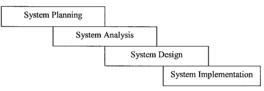
Rapid Application Development (RAD) is a system development methodology created to decrease time needed to design and implement Information Systems radically. A Sashimi development model will be applied in this project development process in order to achieve the objectives of this project. This model will take the traditional waterfall development model stages but there will be minimal overlapping between phases at the end of phase review. This means that it is not required for one phase to be completely accomplished in order to start with the following phase. Figure 3.1 below illustrate the
Sashimi model.
20
System Planning
System Analysis
System Design
System Implementation
Figure 3.1 Sashimi Model with four basic stages of a traditional waterfall model
3.2 Database Development
The Rapid Development Methodology (RDM) will be utilized in order to maximize efficiency in database project development. The RDM will manage all the phases of the project. Appendix 6 shows a life cycle of a GIS database.
3.2.1 Planning
During the planning phase, all information that is related with the database development in this project will be gathered, such as the detailed design of relational and object- relational data models, the available spatial data that will be used, the list of commonly used Database Management Systems and the steps that will be followed in developing the databases. The plan is to start with the Relational database development first and then will be followed with the Object-Relational database development.
3.2.2 Analysis
During the analysis phase, all the gathered information previously in the planning phase will be studied and analyzed. This is in order to ensure that the databases will be design accordingly to the data models implemented in the databases. Besides, the spatial databases also will be chosen. For this project, the Canada database is preferred to be
21
the sample database and the State of Malacca database as the database that will be used in the application. Then, the preferred DBMS for this project is an open source DBMS which is MySQL that will be integrated with ArcView 3.2. For the Object-Relational database system, Oracle 9i will be used.
3.2.3 Three-Steps Database Design
In database development, there are three steps of design that will be involved. They are the Conceptual Design, Logical Design and Physical Design.
i. Conceptual Design
The conceptual design of the GIS system is primarily an exercise in database design.
Database planning is the single most important activity in GIS development. It begins with the identification of the needed data and goes on to cover several other activities collectively termed the data life cycle -identification of data in the needs assessment, inclusion of the data in the data model, creation of the metadata, collection and entry into the database, updating and maintenance, and, finally, retained according to the appropriate record retention schedule. A complete data plan facilitates all phases of data collection, maintenance and retention and as everything is considered in advance, data issues do not become major problems that must be addressed after the fact with considerable difficulty and aggravation.
In the first steps, all available information related to the application is organized, using a high-level conceptual data model. A conceptual modeling is a process that constructs an abstract model that represent the entities, relationships and activities of an enterprise (real world). This is in order to obtain better understanding of the database design, to discover design errors at early stage and to build a solid foundation in order to ensure the quality. During the conceptual design, the Entity Relationship Diagram (ERD) will be prepared. Appendix 7 shows the ERD for Canada Database. Appendix 8 shows the
22
ERD for State of Malacca. Appendix 9 shows an ER diagram for the State of Malacca, with pictograms.
ii. Logical Design
Next step, also called as the logical modeling phase, is related to the actual implementation of the conceptual data model in a commercial DBMS. Data in a commercial database is organized using an implementation model. For the scope of this project, the focused is on the relational and object-relational model.
In the relational model, the data types, relationships, and constraints are all modeled as Relations. Relational database design involved normalization. It is a process that produces a database with minimal redundancy. This involves identifying primary key and foreign key in order to link each of the tables. Conversely, in Object-Relational model, it will involve Object Identity (OID) where each entity is modeled as an object with its own identity, object encapsulates structure and behavior, object state can be accessed by passing messages, objects with common structure and behavior are grouped into classes and classes are arranged in a hierarchy.
Besides, in this logical phase also, the ERD for the State of Malacca resulted from the conceptual design phase will be translated into relational database as shown in Appendix 10. Then, for the object-relational database design, the ERD for the State of Malacca will be translated into UML class diagram as shown in Appendix 11.
23
iii. Physical Design
The physical design deals with the nuts and bolts of the actual computer implementation of the database applications [1]. It is the creation of the database with SQL statements.
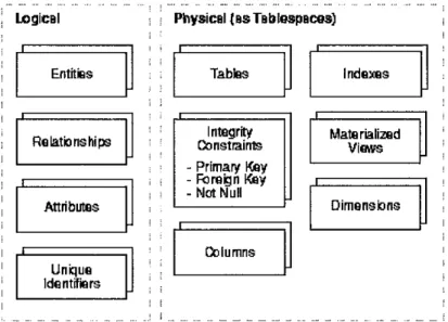
During the physical design process, the data gathered during the logical design phase will be converted into a description of the physical database structure. Physical design decisions are mainly driven by query performance and database maintenance aspects.
Figure 3.2.3 shows the differences between the logical design and physical design.
LogicBl Physical {BsTBblespBces]
1 i > 1 i
Entities
1 '
Tables Indexes
Relationships Integrity
Constraints - Primary Key - Foreign Key - Not Null
Materialized Views
i
: ;
i
Attributes Dimensions
i ;
i
Columns
i
Unique
Identifiers i
i i
Figure 3.2.3. Logical Design compared with Physical Design
3.2.4 Implementation
In the implementation phase, the application that will utilize the database will be developed. First of all, the relational database which is build by using MySQL will be connected with ArcView 3.2 by using the ODBC way as the driver myODBC 3.5.1.
While Oracle 9i will be used for the Object-Relational database system. Then the tables of a the spatial database in MySQL will be added in ArcView and linked with the spatial data's attributes tables that are already in ArcView. Hence, when the query made in MySQL database, the result will also affects the spatial data. Next, an application that
24
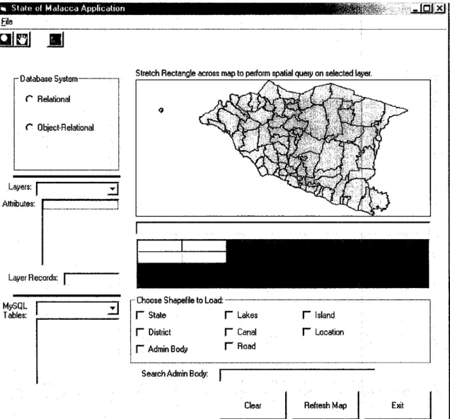
will allow users to view the data and make query from two different databases design will be develop by using Visual Basic 6.0 and MapObjects 2.2. Figure 3.2.4 shows a screen shot of the application.
m State of Malacca Application File
Si
-Database System
C Relational
C Object-Relational
Layers:
Attributes:
Layer Records:
MySQL
Tables: H
sJBffl
Stretch Rectangle across map to perform spatial query on selected layer
- Choose Shape!lie to Load:
r~ State I- Lakes I- Island
H District f~ Canal f" Location
r Admin Body T Road
Search Admin Body:
Clear Refresh Map Exit
Figure 3.2.4 The Graphical User Interface of the State of Malacca Application
25
3.3 Tools Required
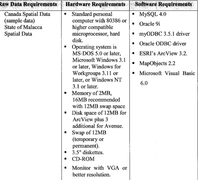
The tools required for this project can be categorized into three categories, which include the raw data requirements, hardware requirements and software requirements.
For the raw data requirements, a digital map is needed. Digitized data of State of Malacca is obtained and a sample data, which is Canada Spatial Database, will be used
in this project.
On hardware requirements for this project, a Standard personal computer with 80386 or higher compatible microprocessor, hard disk is required. The operating system is MS-
DOS 5.0 or later, Microsoft Windows 3.1 or later, Windows for Workgroups 3.11 orlater, or Windows NT 3.1 or later, memory of 2MB required, 16MB recommended with 12MB swap space, the disk space of 12MB for ArcView plus 3 additional for Avenue (subject to change) (Not including data), swap of 12MB (temporary or permanent),
release media with 3.5" diskettes and CD-ROM and monitor with VGA or better resolution.
Software required involved in this project includes MySQL 4.0, Oracle 9i, myODBC
3.5.1 and Oracle ODBC driver will be used as the center of databases that will beimplemented in ESRI's ArcView 3.2. MapObjects 2.2 and Microsoft Visual Basic 6.0 will be used for the application development purposes. Table 3.3 summarized the tools
required in this project.
26
Raw Data Requirements Hardware Requirements Software Requirements
• Canada Spatial Data (sample data)
• State of Malacca
Spatial Data
• Standard personal computer with 80386 or higher compatible microprocessor, hard
disk.
• Operating system is MS-DOS 5.0 or later, Microsoft Windows 3.1
or later, Windows for Workgroups 3.11 or later, or Windows NT
3.1 or later.
• Memory of 2MB,
16MB recommended
with 12MB swap space
• Disk space of 12MB for ArcView plus 3
additional for Avenue.
• Swap of 12MB (temporary or permanent).
• 3.5" diskettes.
• CD-ROM
• Monitor with VGA or better resolution.
• MySQL 4.0
• Oracle 9i
• myODBC 3.5.1 driver
• Oracle ODBC driver
• ESRI's ArcView 3.2.
• MapObjects 2.2
• Microsoft Visual Basic 6.0
Table 3.3. List of raw data requirements, hardware requirements and software requirements for this project.
27
CHAPTER 4
RESULTS AND DISCUSSION
4. RESULTS AND DISCUSSIONS
This chapter compiles the current findings or outcomes of the project work. There has been some information, coming from journals and online resource. According to findings from different sources, the consistency of relational database and object- relational database has been discussed in this chapter.
4.1 Consistency of Relational Database System in State of Malacca Application
During developing the relational database for State of Malacca Application, I have discovered that that consistency isn't as much of a problem in relational data models as relational database design involves normalization and it uses different types of integrity constraints to insure consistency within the system. The most used and well-known ones are entity integrity, referential integrity, and foreign key constraints. However, it is very easy to make a mistake in the process and develop too many tables, or assign attributes to the wrong table.
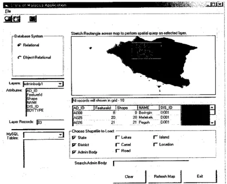
Figure 4.1.1 shows the result for the selected spatial queries from MySQL relational database. As we can see, when user performed spatial queries of the selected admin bodies, the resulted table will contain admin id, feature id, shape, name and district id.
As the admin body table is in relational data model, the admin id is the primary key
28
while the district id is the foreign key that will referring to the district table. The implementation of the primary key and foreign key in relational tables is to insure the database integrity and consistency.
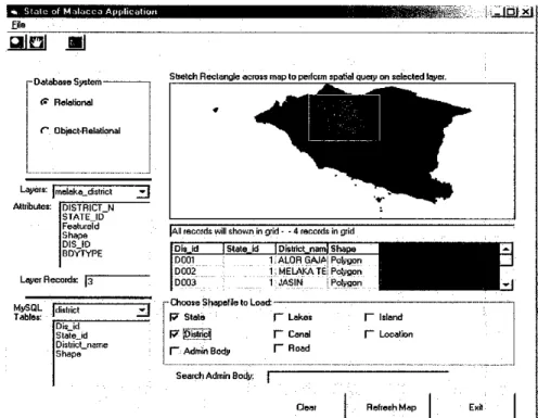
However, the information given in the resulted table is not enough. Geographical data in GIS applications usually are interrelated with the layers are related to each other. For example, if the user wants to know which district does the selected admin bodies belong to, the user will need to retrieve the district information from the district table in MySQL as shown in Figure 4.1.2. This process will increase the time for retrieving information. Besides, when there are many tables related to each other, GIS application
developer will be likely to make mistakes easily. For example, if the district id for
admin body Beringin has been incorrectly entered as D002, the user will get wrong information on the district that actually contains Beringin admin body. Figure 4.1.3 shows result of the entered search for an admin body, which is Beringin in relational database. The search process is fast but with only limited data provided. Only the data from admin body table will be shown.ESo
-Datefaase System
#• Relational
(~ Object-Relational
Lwnfdminbodyl z}
Attributes; M3JD -ealureld shape UAME
DISID
3DYTYPE
Layer Records: [03
MySQL
Tables: ±1
~mm
Stretch Rectangle across map to perturn spatial queor on selected layer
^^•H^^l
'V ^^^^^TF^
Mlrecords will shown in grid -10
AD ID JFeatureld IShape INAME |DIS ID fj^gagwm-
AGOB 8 H Hpimnm UUU1 i^^^H
A025 20 ?n M*t*k<-i< n'nm E^^H
A02G 21 21 Pegoh DUU1 j^^J
Hd
[-Choose ShapeHe to Load:
5 P" State V Lakes
P" District f~ Canal
|? Admin Body f~ Hoad
Search Admin Body:
r Island f~ LocaHon
Refresh Map
Figure 4.1.1 Result shown for the selected spatial queries from MySQL relational
database.
29
£_
jttal ml
- Database System - f? Relational
r Object-Relational
Layers: ]mo|ake_district Attributes: (DISTRICTJJ
STATEJD Featureld Shape DISJD BDYTYPE
Layer Records: [J"
MySQL Tables: district
Dis_id Statejd DistricLiame Shape
"3
_3
S&elch Rectangle across map to perform spatial queiy on selected layer.
Allrecords will shown in grid - - 4 records in grid
Dfajd |state_id IPistirct_narn| Shape"
DC01 D002 D003
I.ALORGAJAIPo&gon 1;MELAKATE| Polygon 1 JASIN i Polygon -Choose Shapelle to Load:
f7 State J- Lakes
P i__§1 V Canal
r Admin Body T Road
Search Admin Body:
r Island I- Location
Refresh Map
____!
Figure 4.1.2 District table attributes from MySQL database.
IKHHWi'llHPI
aiOJ __]
-Database System (? Relational
C Obiect-Refational
Layers: |adminbadyi Attributes: JADJD
Featureld Shape NAME DISJD BDYTYPE
Layer Records: |q3
MySQL Tables:
district
Dis_id Statejd DistiicLname Shape
~_3
_J
MfiK_ i_J___l
Stretch Rectangle across map to performspatial query on selected layer.
All records will shown in grid -11
AD ID I Featureld Shape | NAME DIS ID
AQ08 A024 A025
8 IS i " 20
8: Beringin
^3\ SungarBulo 20;Melekek
D001 D001 booi -Choose Shapedle loLoad —______
W State f~ Lakes I- Island
I? District f~ Canal I™" Location
F7 Admin Body T~ Road
SearchAdminBody: {Beringin
Reliesh Map Exit
Figure 4.1.3 Result of the entered search for an admin body, which is Beringin in
relational database.
30
Besides, the disadvantages of relational database become obvious with a closer look at the nature of GIS data. This is because, GIS data contains arbitrary data types including numeric and short string data, large unstructured data such as textures, complex structured data such as the geometry buildings and finally compound objects that are comprised of such data. Relational database lack of the mechanism to deal with this kind of data as its tabular approach does not allow a suitable modeling of complex hierarchical objects. The relational database also is not very suitable in handling the spatial data but it is preferably used for handling the attributes data in most of GIS application.
Furthermore, there are limitations in relational design in representing complex objects related with complex relationships in GIS. Representing such objects and relationships in the relational model implies that the objects must be decomposed into a large number of tuples. Thus, a considerable number of joins is necessary to retrieve an object and, when tables are too deeply nested, performance is significantly reduced. Hence, currently, Object Relational Database Management System (ORDBMS) is being used to store data about spatial features.
Some relational database issues with ArcView are that ArcView only allows joins using a single column which will forces developers to resort to elaborate procedures to build a single-column key. Then, ArcView does not handle many-to-many relationships well as a one-to-many join yields an arbitrary value in the joined table while a link rather than a join provides some many-to-one capability but it is limited. There are also limited tools
for aggregation and grouping.
31
• H™& _ •_"»• U» B i U K tH _ •_
ill b h i mqnoi w narami na tnn__i i d e e
TTapriBhuUM
^ ^ • ^ ^ ^ ^ i ^ H I ^ B H M I s r ;
a ™""'"iS"" 0 _ & £&fr
^ ^ w n ?
...j*ri.h, _, tjM,__
• i l . - . . , .J h r t j . « . _ ,
yig™..._ ; VI «jg,_i_,'
Vj.u_.
H
Hiw.itfiun |> JEUVAlEMGflri -
41tUta 40U
4H*ki 40B
U b u
B A h m l n £UAI . t o Fundi awh
B!ta_
B**£ •6»?I-S* «og
[Mag H £*• AD97
KMJfa M b [nidi m
Mftttaiorii S o v U ,
»S?1 1j»_ KWaTi^di Mel
PrtonPri..Snddi ft Lfd^ AOO
— . . . ~ *
Figure 4.1.4 Query Result for "Admin-Body in Melaka Tengah District".
32
4.2 Consistency of Object-Relational Database System in GIS Application
As the name suggest, object-relational database are actually based on relational database. The major advantage of object-relational database is that they are able to deal with complex data types. ORDBS also support the robust transaction and data- management features of RDBMS while at the same time offer a limited form of flexibility of object-oriented databases. Developing the State of Malacca database in Object-Relational database system are easier than in relational database system as it uses the objects concept. Although this does not allow aggregation structures, it does allow generalization structures. This allows object classes lower in a hierarchy to inherit attributes from classes higher in the hierarchy.
Figure 4.2.1 shows the result for the selected spatial queries from Oracle object- relational database. Through the implementation of object-relational database in GIS application, the user can view all the related information of the admin bodies. This is because the geographical data can be stored in hierarchy by using object inheritance concept. The admin body table, which is the subclass, can directly inherit all the attributes contained in the district table, which is the super class. Thus, the user will be able to view all related information of a particular layer with a single query.
Furthermore, the process of retrieving information in object-relational database will be faster and more efficient. The searching function also will be faster with all the necessary information related to the particular layer selected by the user when performing the spatial query. For example, when a user search for an admin body named Beringin, the application will search the particular area and provide all the necessary information related to the area very efficiently by inherit all other information from the super class table as shown in Figure 4.2.2. which consists of the state id, state name, district id, district name, admin id and admin name. Table 4.2a summarize the characteristic of relational, object-relational database systems and the ratings.
33
![Figure 1.1. Evolution of databases [1].](https://thumb-ap.123doks.com/thumbv2/azpdforg/10277831.0/13.829.76.751.428.1158/figure-1-1-evolution-of-databases-1.webp)