Safety Manual — Translation
TB…-L…-FDIO1-2IOL
Safety Block I/O Modules
Table of Contents
Table of Contents
1 About this manual ... 5
1.1 Scope... 5
1.2 Explanation of symbols used... 5
1.3 Additional documents ... 6
2 For your safety ... 7
2.1 General safety notes... 7
2.2 Residual risks (EN ISO 12100:2010) ... 7
2.3 Warranty and liability... 7
2.4 Notes on explosion protection... 8
2.5 Ex approval requirements for use in Ex area ... 8
3 Safety Integrity Level/Performance Level/Category... 9
4 Product Description... 10
4.1 Intended use ... 10
4.1.1 Reasonably foreseeable misuse ... 10
4.2 Device overview ... 11
4.2.1 Type label ... 13
4.3 Switches and connectors... 14
4.4 Block diagram... 16
5 Safety function ... 17
6 Safety planning ... 18
6.1 Prerequisites ... 18
6.2 Reaction time... 18
6.3 Safety characteristic data ... 18
7 Operating instructions... 19
7.1 Before operation ... 19
7.1.1 Mounting... 20
7.1.2 Connecting ... 22
7.1.3 Addressing — TBPN-L…-FDIO1-2IOL ... 23
7.1.4 Addressing — TBIP-L…-FDIO1-2IOL ... 25
7.1.5 Web server login... 28
7.1.6 Configuring... 28
7.2 Operating ... 29
7.2.1 LED displays... 29
7.2.2 Output error behavior ... 32
7.2.3 Decommissioning ... 32
8 Appendix: wiring diagrams... 33
8.1 Ethernet ... 33
8.2 Power supply ... 33
8.3 Safety inputs (FDI) ... 34
8.4 Safety in-/outputs (FDX) ... 34
8.5 DXP channels ... 35
8.6 IO-Link channels... 35
Table of Contents
Hans Turck GmbH & Co. KG | T +49 208 4952-0 | [email protected] | www.turck.com V02.00 | 2022/07 | 3
9 Appendix: switching examples ... 36
9.1 Inputs ... 36
9.2 Outputs ... 37
10 Appendix: designations and abbreviations... 38
11 Appendix: function tests ... 38
12 Appendix: document history ... 38
13 Appendix: technical data... 39
13.1 Derating... 41
14 Appendix: directives and standards... 42
14.1 National and international directives and standards ... 42
14.2 Cited standards ... 42
15 Appendix: approvals and markings ... 43
16 Turck subsidiaries — contact information... 44
Table of Contents
Explanation of symbols used
Hans Turck GmbH & Co. KG | T +49 208 4952-0 | [email protected] | www.turck.com V02.00 | 2022/07 | 5
1 About this manual
This safety manual contains all information that is required by users to operate the device in functional safety systems.
Read this manual carefully before using the device. This document addresses only functional safety according EN ISO 13849-1 and IEC 61508. Other issues are not considered.
All instructions must be followed in order to assure functional safety.
Always make sure that this is the latest version of the safety manual at www.turck.com.
The German version is considered the definitive document. Every care was taken in the produc- tion of the translations of this document. If any uncertainties arise in the interpretation of the description, reference the German version of the Safety Manual or contact Turck.
1.1 Scope
This safety manual applies to the following Turck safety modules:
PROFIsafe module:
n TBPN-L1-FDIO1-2IOL n TBPN-LL-FDIO1-2IOL CIP Safety devices:
n TBIP-L4-FDIO1-2IOL n TBIP-L5-FDIO1-2IOL n TBIP-LL-FDIO1-2IOL
1.2 Explanation of symbols used
The following symbols are used in these instructions:
DANGER
DANGER indicates a dangerous situation with high risk of death or severe injury if not avoided.
WARNING
WARNING indicates a dangerous situation with medium risk of death or severe in- jury if not avoided.
CAUTION
CAUTION indicates a dangerous situation of medium risk which may result in minor or moderate injury if not avoided.
NOTICE
NOTICE indicates a situation which may lead to property damage if not avoided.
NOTE
NOTE indicates tips, recommendations and useful information on specific actions and facts. The notes simplify your work and help you to avoid additional work.
u
CALL TO ACTIONThis symbol denotes actions that the user must carry out.
a
RESULTS OF ACTIONThis symbol denotes relevant results of actions.
Additional documents
1.3 Additional documents
The following additional documents are available online at www.turck.com:
n Data sheet
n Declarations of conformity (current versions) n Approvals
n Notes on Use in Ex zone 2 and 22 (100022986)
Warranty and liability
Hans Turck GmbH & Co. KG | T +49 208 4952-0 | [email protected] | www.turck.com V02.00 | 2022/07 | 7
2 For your safety
The product is designed according to state-of-the-art technology. However, residual risks still exist. Observe the following warnings and safety notices to prevent damage to persons and property. Turck accepts no liability for damage caused by failure to observe these warning and safety notices.
2.1 General safety notes
n The device may only be assembled, installed, operated, parameterized and maintained by professionally-trained personnel.
n The device may only be used in accordance with applicable national and international regu- lations, standards and laws.
n The device meets the EMC requirements for industrial areas. When used in residential areas, take measures to avoid radio interference.
n The Performance Level as well as the safety category according to EN ISO 13849-1 depend on the external wiring, the application, the choice of the control devices as well as their ar- rangement on the machine.
n The user has to execute a risk assessment according to EN ISO 12100:2010.
n Based on the risk assessment a validation of the complete plant/machine has to be done in accordance with the relevant standards.
n Operating the device beyond the specification can lead to malfunctions or to the destruction of the device. The installation instructions must be observed.
n For trouble-free operation, the device must be properly transported, stored, installed and mounted.
n For the release of safety circuits in accordance with EN/IEC 60204-1, EN ISO/ISO 13850 only use the output circuits of connectors C2, C3, C4, C5 and C7 or respectively X2, X3, X4, X5 and X7.
n For connecting sensors and actuators in safety related applications only use the connectors C0…C3 or X0…X3.
n Change the default password of the integrated web server after the first login. Turck recom- mends using a secure password.
2.2 Residual risks (EN ISO 12100:2010)
The wiring proposals described in the following have been tested under operational conditions with the greatest care. Together with the connected periphery of safety related equipment and switching devices they fulfill relevant standards.
Residual risks remain, if
n the proposed wiring concept is is changed and connected safety related devices or protect- ive devices are possibly not or insufficiently included in the safety circuit.
n the operator does not observe the relevant safety regulations specified for the operation, ad- justment and maintenance of the machine. Observe intervals for inspection and mainten- ance of the machine.
Failure to follow these instructions can result in serious injury or equipment damage.
2.3 Warranty and liability
Any warranty and liability is excluded for:
n Improper application or not intended use of the product n Non-observance of the user manual
n Mounting, installation, configuration or commissioning by unqualified persons
Ex approval requirements for use in Ex area
2.4 Notes on explosion protection
n When operating the device in a hazardous area, the user must have a working knowledge of explosion protection (IEC/EN 60079-14, etc.).
n Observe national and international regulations for explosion protection.
n Only use the device within the permitted operating and ambient conditions (see Certifica- tion data and conditions resulting from the Ex-approval).
2.5 Ex approval requirements for use in Ex area
n Only use the device in an area with no more than pollution degree 2.
n Only disconnect and connect circuits when no voltage is applied.
n Only operate the switches if no voltage is present.
n Connect the metal protective cover to the equipotential bonding in the Ex area.
n Ensure impact resistance in accordance with EN IEC 60079-0 — alternative measures:
– Install the device in the TB-SG-L protective housing (available in the set with Ultem window: ID 100014865) and replace the service window with an Ultem window.
– Install the device in an area offering impact protection (e.g. in robot arm) and attach a warning: ”DANGER: Only connect and disconnect circuits when no voltage is present.
Do not operate switches when energized.”
n Do not install the device in areas critically exposed to UV light.
n Prevent risks caused by electrostatic charge.
n Protect unused connectors with dummy plugs to ensure protection class IP67.
Hans Turck GmbH & Co. KG | T +49 208 4952-0 | [email protected] | www.turck.com V02.00 | 2022/07 | 9
3 Safety Integrity Level/Performance Level/Category
The devices are rated for applications rated to:
n SIL3 according to EN 61508 and EN 62061 n Category 4/PLe according to EN ISO 13849-1
Intended use
4 Product Description
The TBPN- L…-- FDIO1-2IOL are safety block I/O modules for safety applications with PROFIsafe via PROFINET. The TBIP-L…-FDIO1-2IOL are a safety block I/O modules for safety applications using CIP Safety via EtherNet/IP.
The devices provide two SIL3-inputs (FDI) to connect 1- and 2-channel mechanical safety switches and electronic safety sensors (OSSD). Two further SIL3-channels (FDX) can be freely used as inputs (FDI) or outputs (FDO). The safety-related outputs are used for the safety-related disconnection of loads (resistive up to 2 A).
For non-safety relevant functions, the Safety Hybrid module has additional universal input channels as well as two IO-Link master channels for the connection of IO-Link sensors and IO-Link hubs for expansion to up to 32 I/O signals.
4.1 Intended use
The TB…-L…-FDIO1-2IOL are decentralized safety modules for PROFIsafe or CIP Safety.
The devices collect field signals and forward them safely to a PROFIsafe or CIP Safety master.
Due to an extended temperature range from -40…+70 °C and IP67/IP69K protection the devices can be used directly on the machine demanding industrial environments.
The TB…-L…-FDIO1-2IOL are used for controlling signaling devices as for example emergency stop buttons, position switches or electro-sensitive protective equipment ESPEs which are used to ensure human, material or machine protection.
Digital sensors and actuators can be connected to the DXP channels. The two IO-Link master channels are used to connect IO-Link sensors and IO-Link hubs for expansion to up to 32 I/O signals.
The device is specified for the operation in industrial environment. If it is used in residential or mixing areas, radio interference may occur.
4.1.1 Reasonably foreseeable misuse
The devices are not suitable for:
n Outdoor use
n The permanent use in liquids n The use in Zone 0 and Zone 1
Modifications to the device
The device must not be modified either constructionally or technically.
Device overview
Hans Turck GmbH & Co. KG | T +49 208 4952-0 | [email protected] | www.turck.com V02.00 | 2022/07 | 11
4.2 Device overview
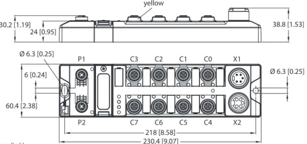
TBPN-L…-FDIO1-2IOL
mm [Inch]
38.8 [1.53]
Ø 6.3 [0.25]
218 [8.58]
230.4 [9.07]
6 [0.24]
60.4 [2.38]
Ø 6.3 [0.25]
30.2 [1.19]
24 [0.95]
yellow
C7
P2 C6 C5 C4
C3
P1 C2 C1 C0
X2 X1
Fig. 1: TBPN-L1-FDIO1-2IOL
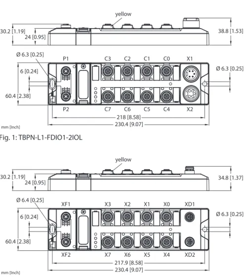
mm [Inch]
34.8 [1.37]
Ø 6.3 [0.25]
217.9 [8.58]
230.4 [9.07]
6 [0.24]
60.4 [2.38]
Ø 6.4 [0.25]
30.2 [1.19]
24 [0.95]
yellow
X7
XF2 X6 X5 X4
X3
XF1 X2 X1 X0
XD2 XD1
Fig. 2: TBPN-LL-FDIO1-2IOL
Device overview
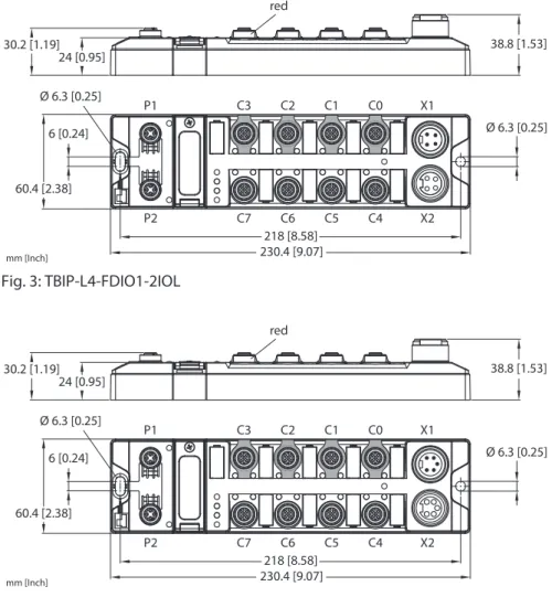
TBIP-L…-FDIO1-2IOL
mm [Inch]
38.8 [1.53]
Ø 6.3 [0.25]
218 [8.58]
230.4 [9.07]
6 [0.24]
60.4 [2.38]
Ø 6.3 [0.25]
30.2 [1.19]
24 [0.95]
red
C7
P2 C6 C5 C4
C3
P1 C2 C1 C0
X2 X1
Fig. 3: TBIP-L4-FDIO1-2IOL
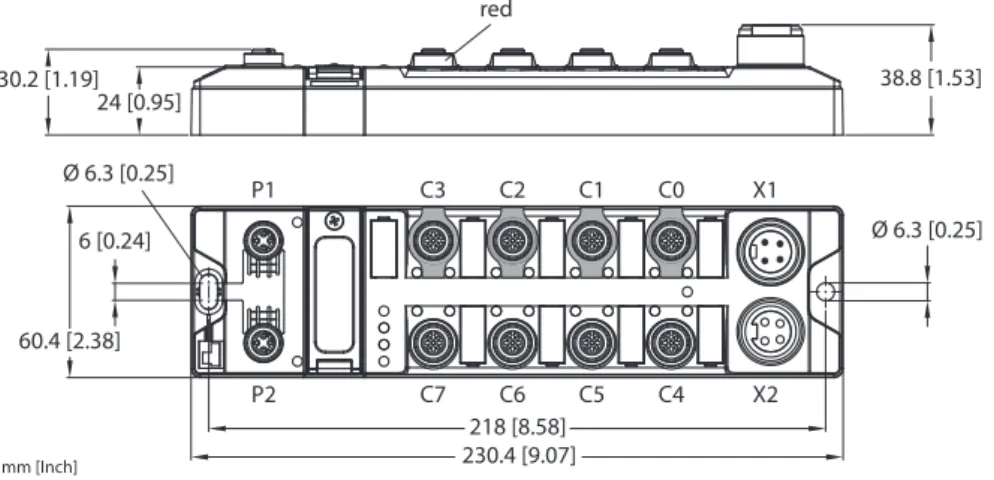
mm [Inch]
38.8 [1.53]
Ø 6.3 [0.25]
218 [8.58]
230.4 [9.07]
6 [0.24]
60.4 [2.38]
Ø 6.3 [0.25]
30.2 [1.19]
24 [0.95]
red
C7
P2 C6 C5 C4
C3
P1 C2 C1 C0
X2 X1
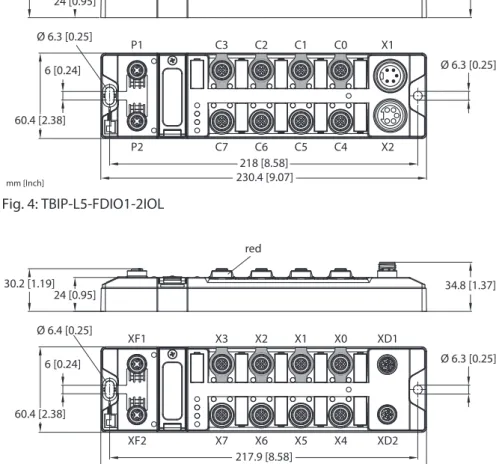
Fig. 4: TBIP-L5-FDIO1-2IOL
mm [Inch]
34.8 [1.37]
Ø 6.3 [0.25]
217.9 [8.58]
230.4 [9.07]
6 [0.24]
60.4 [2.38]
Ø 6.4 [0.25]
30.2 [1.19]
24 [0.95]
red
X7
XF2 X6 X5 X4
X3
XF1 X2 X1 X0
XD2 XD1
Fig. 5: TBIP-LL-FDIO1-2IOL
Device overview
Hans Turck GmbH & Co. KG | T +49 208 4952-0 | [email protected] | www.turck.com V02.00 | 2022/07 | 13
4.2.1 Type label
TBPN-L1-FDIO1-2IOL
Ident-No.: 6814053 HW:
Charge code:
YoC:
Hans Turck GmbH & Co. KG D-45466 Mülheim a. d. Ruhr www.turck.com Made in Germany
TBPN-LL-FDIO1-2IOL
Ident-No.: 100029879 HW:
Charge code:
YoC:
Hans Turck GmbH & Co. KG D-45466 Mülheim a. d. Ruhr www.turck.com Made in Germany
Fig. 6: Type label TBPN-L1-FDIO1-2IOL Fig. 7: Type label TBPN-LL-FDIO1-2IOL
TBIP-L4-FDIO1-2IOL
Ident-No.: 100000360 HW:
Charge code:
YoC:
Hans Turck GmbH & Co. KG D-45466 Mülheim a. d. Ruhr www.turck.com Made in Germany
TBIP-L5-FDIO1-2IOL
Ident-No.: 6814056 HW:
Charge code:
YoC:
Hans Turck GmbH & Co. KG D-45466 Mülheim a. d. Ruhr www.turck.com Made in Germany
Fig. 8: Type label TBIP-L4-FDIO1-2IOL Fig. 9: Type label TBIP-L5-FDIO1-2IOL
TBIP-LL-FDIO1-2IOL
Ident-No.: 100027260 HW:
Charge code:
YoC:
Hans Turck GmbH & Co. KG D-45466 Mülheim a. d. Ruhr www.turck.com Made in Germany
Fig. 10: Type label TBIP-LL-FDIO1-2IOL
Switches and connectors
4.3 Switches and connectors
TBPN-L1-FDIO1-2IOL
Designation Meaning
C4
C5
C6
C7 C0
C1
C2
C3
X2 X1
P2 P1
FE
F- Address
X1 Power IN
X2 Power OUT
C0 FDI0/1, safety-related input C1 FDI2/3, safety-related input C2 FDX4/5, safety-related input C3 FDX6/7, safety-related input C4 DXP8/9, standard in-/outputs
(safe shutdown via FSO0 possible) C5 DXP10/11, standard in-/outputs
(safe shutdown via FSO0 possible)
C6 IOL, IO-Link port 1
C7 IOL, IO-Link port 2 (safe shutdown via FSO 1 possible)
F-Address Rotary coding switch for address setting for PROFIsafe (F-address setting)
P1 Ethernet 1
P2 Ethernet 2
FE Functional earth
TBPN-LL-FDIO1-2IOL
Designation Meaning
X4
X5
X6
X7 X0
X1
X2
X3
XD2 XD1
XF2 XF1
XE
F- Address
XD1 Power IN
XD2 Power OUT
X0 FDI0/1, safety-related input X1 FDI2/3, safety-related input X2 FDX4/5, safety-related input X3 FDX6/7, safety-related input X4 DXP8/9, standard in-/outputs
(safe shutdown via FSO0 possible) X5 DXP10/11, standard in-/outputs
(safe shutdown via FSO0 possible)
X6 IOL, IO-Link port 1
X7 IOL, IO-Link port 2 (safe shutdown via FSO 1 possible)
F-Address Rotary coding switch for address setting for PROFIsafe (F-address setting)
XF1 Ethernet 1
XF2 Ethernet 2
FE Functional earth
Switches and connectors
Hans Turck GmbH & Co. KG | T +49 208 4952-0 | [email protected] | www.turck.com V02.00 | 2022/07 | 15
TBIP-L4-FDIO1-2IOL/TBIP-L5FDIO1-2IOL
Designation Meaning
C4
C5
C6
C7 C0
C1
C2
C3
X2 X1
P2 P1
FE
IP Address
X1 Power IN
TBIP-L4-4FDI-4FDX: 4-pin TBIP-L5-4FDI-4FDX: 5-pin
X2 Power OUT
TBIP-L4-4FDI-4FDX: 4-pin TBIP-L5-4FDI-4FDX: 5-pin C0 FDI0/1, safety-related input C1 FDI2/3, safety-related input C2 FDX4/5, safety-related input C3 FDX6/7, safety-related input C4 DXP8/9, standard in-/outputs
(safe shutdown via FSO0 possible) C5 DXP10/11, standard in-/outputs
(safe shutdown via FSO0 possible)
C6 IOL, IO-Link port 1
C7 IOL, IO-Link port 2 (safe shutdown via FSO 1 possible)
IP Address Rotary coding switch for address setting (last byte of the IP address for the safe function unit)
P1 Ethernet 1
P2 Ethernet 2
FE Functional earth
TBIP-LL-FDIO1-2IOL
Designation Meaning
X4
X5
X6
X7 X0
X1
X2
X3
XD2 XD1
XF2 XF1
XE
IP Address
XD1 Power IN
XD2 Power OUT
X0 FDI0/1, safety-related input X1 FDI2/3, safety-related input X2 FDX4/5, safety-related input X3 FDX6/7, safety-related input X4 DXP8/9, standard in-/outputs
(safe shutdown via FSO0 possible) X5 DXP10/11, standard in-/outputs
(safe shutdown via FSO0 possible)
X6 IOL, IO-Link port 1
X7 IOL, IO-Link port 2 (safe shutdown via FSO 1 possible)
IP Address Rotary coding switch for address setting (last byte of the IP address for the safe function unit)
XF1 Ethernet 1
XF2 Ethernet 2
FE Functional earth
Block diagram
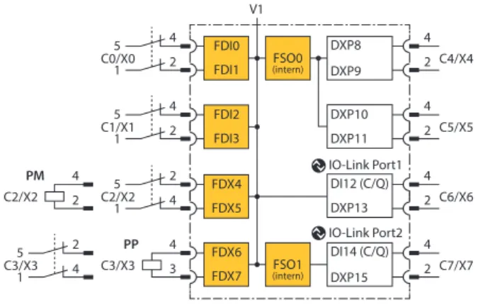
4.4 Block diagram
2 4 C0/X0
V1
2 4 C1/X1
4 2 1 5
1 5
1 5 C2/X2
4 2 1 5
C3/X3 3
4 C3/X3
C4/X4
C5/X5
C6/X6
C7/X7 2 4
2 4
2 4
2 4 FSO0
(intern)
2 4 C2/X2
FSO1 (intern)
DXP9 DXP8
DXP11 DXP10
DXP13 DI12 (C/Q)
DXP15 DI14 (C/Q) IO-Link Port1
IO-Link Port2 PM
PP
FDI0 FDI1
FDI2 FDI3
FDX4 FDX5
FDX6 FDX7
Fig. 11: Block diagram TBPN-L…-FDIO1-2IOL
2 4 C0/X0
V1
2 4 C1/X1
4 2 1 5
1 5
1 5 C2/X2
4 2 1 5
C3/X3 3
4 C3/X3
C4/X4
C5/X5
C6/X6
C7/X7 2 4
2 4
2 4
2 4 FSO0
(intern)
2 4 C2/X2
FSO1 (intern)
DXP9 DXP8
DXP11 DXP10
DXP13 DI12 (C/Q)
DXP15 DI14 (C/Q) IO-Link Port1
IO-Link Port2 PM
PP
FDI0 FDI1
FDI2 FDI3
FDX4 FDX5
FDX6 FDX7
Fig. 12: Block diagram TBIP-L…-FDIO1-2IOL
Hans Turck GmbH & Co. KG | T +49 208 4952-0 | [email protected] | www.turck.com V02.00 | 2022/07 | 17
5 Safety function
The TB…-L…-FDIO1-2IOL provide two safe digital SIL3 inputs (FDI) and two SIL3-connectors (FDX), configurable as in- or outputs.
The following devices can be connected to the safety inputs:
n 1- and 2-channel safety switches and sensors
n Contact based switches, e.g. emergency switches, protective door switches n Sensors with OSSD switching outputs
n Antivalently switching OSSD sensors
The two safe SIL3 outputs can be used PP- or PM-switching.
Safe Status
In the safe state the device outputs are in LOW-state (0). The inputs report a LOW-state (0) to the logic.
Fatal Error
n Incorrect wiring at the output (i.e. capacitive load, energetic recovery) n Short-circuit at the line control output T2
n Incorrect power supply n Strong EMC disturbances n Internal device error
Safety characteristic data
6 Safety planning
The operator is responsible for the safety planning.
6.1 Prerequisites
Perform a hazard and risk analysis.
Develop a safety concept for the machine or plant.
Calculate the safety integrity for the complete machine or plant.
Validate the complete system.
6.2 Reaction time
If the device is operated with higher availability, the max. reaction time is extended (see ”Safety Characteristic Data” [} 18]).
In addition to the reaction time in the device, reaction times of the further Safety components have to be system considered eventually. Please find the respective information in the tech- nical data of the respective devices.
Further information about the reaction time can be found in the online help for the Turck Safety Configurator.
6.3 Safety characteristic data
Characteristic data Value Standard
Performance Level (PL) e EN/ISO 13849-1:2015
Safety category 4
MTTFD > 100 years (high)
Permissible duration of use (TM) 20 years
DC 99 %
SIL (Safety Integrity Level) 3 EN 61508
PFH 3.85 × 10⁻⁹ 1/h
Maximum on-time 12 months
SIL CL 3 EN 62061:2005+
Cor.:2010+A1:2013+A2:2015
PFHD 5.08 × 10⁻⁹ 1/h
SFF 98.22 %
Max. reaction time in case of shutdown
Value Standard
TBPN-L…-FDIO1-2IOL
PROFIsafe > local output 25 ms EN 61508
Local input > PROFIsafe 20 ms Local input <> local output 35 ms TBIP-L…-FDIO1-2IOL
CIP Safety > local output 25 ms EN 61508
Local input > CIP Safety 20 ms Local input <> local output 35 ms
Before operation
Hans Turck GmbH & Co. KG | T +49 208 4952-0 | [email protected] | www.turck.com V02.00 | 2022/07 | 19
7 Operating instructions
In case of a safety application, register the devices under www.turck.com/SIL.
Only allow trained and qualified personnel to assemble, install, commission and service the devices.
The devices are not specified for a certain application. Make sure that application-specific aspects are considered.
Replace the devices before the expiration of the permissible duration of use (see Safety Characteristic Data [} 18]).
Execute a functional test every twelve months.
Do not repair devices. If problems occur with regard to functional safety, Turck must be notified immediately and the devices must be returned immediately to:
Hans Turck GmbH & Co. KG Witzlebenstraße 7
45472 Mülheim an der Ruhr Germany
In case of device errors which lead to the safe state, measures to be taken which guaran- tee the safe state for the further operation of the complete control system.
Dangerous failures to be reported immediately to Turck.
7.1 Before operation
The operator of the machine or the plant in which the safety related system is used, is respons- ible for the correct and safe overall function of every single safety component.
Carry out a validation of the safety category for the complete system depending on the selection of the used safety components.
Before operation
7.1.1 Mounting
Mounting the device in Zone 2 and Zone 22
In Zone 2 and Zone 22, the devices can be used in conjunction with the protective housing set TB-SG-L (ID 100014865).
DANGER
Potentially explosive atmosphere Risk of explosion through spark ignition For use in Zone 2 and Zone 22:
Only install the device if there is no potentially explosive atmosphere present.
Observe requirements for Ex approval.
Unscrew the housing. Use Torx T8 screwdriver.
Replace the service window with the enclosed Ultem window.
Place the device on the base plate of the protective housing and fasten both together on the mounting plate [} 21].
Connect the device [} 22].
Mount and screw the housing cover according to the following figure. The tightening torque for the screws is 0.5 Nm.
Fig. 13: Mounting the device in protection housing TB-SG-L
Before operation
Hans Turck GmbH & Co. KG | T +49 208 4952-0 | [email protected] | www.turck.com V02.00 | 2022/07 | 21
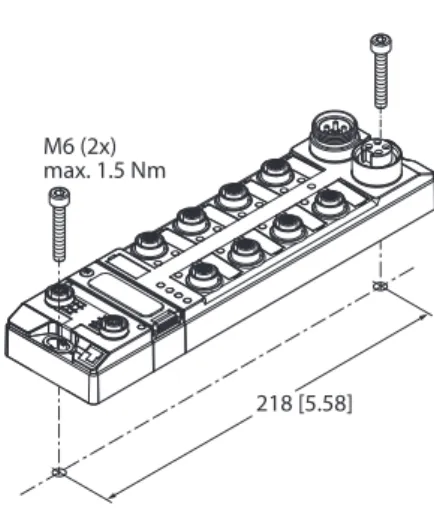
Mounting onto a mounting plate NOTICE
Mounting on uneven surfaces
Device damage due to stresses in the housing
Fix the device on a flat mounting surface.
Use two M6 screws to mount the device.
The device can be screwed onto a flat mounting plate.
Attach the module to the mounting surface with two M6 screws. The maximum tighten- ing torque for the screws is 1.5 Nm.
Avoid mechanical stresses.
Optional: Ground the device.
218 [5.58]
M6 (2x) max. 1.5 Nm
Fig. 14: Installing
Before operation
7.1.2 Connecting
Connecting the device in Zone 2 and Zone 22 WARNING
Intrusion of liquids or foreign bodies through leaking connections Danger to life due to failure of the safety function
Tighten M12 connectors with a tightening torque of 0.6 Nm.
Only use accessories that guarantee the protection class.
Close unused M12 connectors with the supplied screw caps. The tightening torque for the screw caps is 0.5 Nm.
Use appropriate 7/8" sealing caps, e.g. type RKMV-CCC. The caps not part of the scope of delivery.
Connecting Ethernet
Connect the device to Ethernet according to the pin assignment [} 33].
Connecting the supply voltage
The externally connectable circuits have to be securely disconnected from the mains supply.
WARNING
Incorrect or defective power supply unit
Danger to life due to dangerous voltages on touchable parts
Only use for SELV or PELV power supplies in accordance with EN ISO 13849-2, which allow a maximum of 60 VDC or 25 VAC in the event of a fault.
Connect the device to the power supply according to the pin assignment [} 33]. The female connectors at the device have the following function:
X1 or XD1: Voltage IN
X2 or XD2: Conduct voltage to next node
Connecting sensors and actuators DANGER
Wrong supply of sensors and actuators Danger to life due to external supply
Exclude external supply.
Guarantee that the inputs are only supplied through the same 24 V source as the device itself.
Connect the sensors and actuators to the in- and outputs according to the respective pin assignment [} 33].
DANGER
Connection of fast reacting loads
Danger to life due to connection failures
Use loads with mechanical or electrical inertia. Positive and negative test pulses have to be tolerated.
Before operation
Hans Turck GmbH & Co. KG | T +49 208 4952-0 | [email protected] | www.turck.com V02.00 | 2022/07 | 23
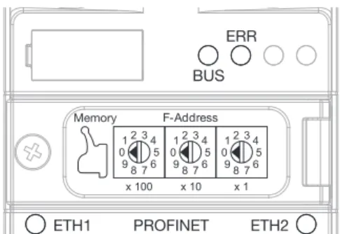
7.1.3 Addressing — TBPN-L…-FDIO1-2IOL
Setting the F address via rotary coding switches
Open the cover above the switches.
Set the F address via the three rotary coding switches under the cover at device.
Execute a power cycle.
BUS ERR
PROFINET
ETH1 ETH2
F-Address
0 98 76
5 34 12
0 98 76
5 34 12
0 98 76
5 34 12
x 100 x 10 x 1
Memory
Fig. 15: Rotary coding switches at the device
In the delivery state, the rotary switches are set to 000 (0 - 0 - 0). Address 000 and addresses
≥ 900 are not valid F addresses.
Switch position Meaning
000 Delivery state, no valid F-address
1…899 F address, accept setting by restarting the device 900 Factory Reset: Resets device to factory settings
901 Erase Memory: Deletes the content of the configuration memory
Before operation
Setting the IP address via the web server
To set the IP address via the web server, the device must be in PGM mode.
Open the web server.
Log on to the device as administrator. The default password for the web server is
“password”.
NOTE
The password is transmitted in plain text.
NOTICE
Inadequately secured devices
Unauthorized access to sensitive data
Change password after first login. Turck recommends using a secure password.
Adapt the password to the requirements of the network security concept of the system in which the devices are installed.
Click Station
Ò
Network Configuration. Change the IP address and, if necessary, the subnet mask and the default gateway.
Write the new IP address, the subnet mask and the default gateway via Submit into the device.
Fig. 16: Webserver — Network configuration TBPN-L…-2FDIO-2IOL
Before operation
Hans Turck GmbH & Co. KG | T +49 208 4952-0 | [email protected] | www.turck.com V02.00 | 2022/07 | 25
7.1.4 Addressing — TBIP-L…-FDIO1-2IOL
The device supports two IP addresses. Whether the secondary IP address is required depends on the application and the CIP Safety Scanner used.
The first three bytes of the Main IP address can be set via the device's web server (IP address in delivery state: 192.168.1.254). The last byte of the IP address Main IP address can either be set via the rotary coding switches at the device, via the Turck Service Tool or via the web server.
NOTE
Turck recommends setting the IP address via the rotary coding switches (Static Rotary) on the device. The rotary mode supports easy device replacement.
n Main IP Address:
IP address of the device to access the device with Turck Safety Configurator, PLC, web server, Turck Service Tool, etc.
n Secondary IP Address:
depending on application possibly without function, must then be 0.0.0.0
NOTE
The Secondary IP address can only be set by using the web server of the device.
Setting the IP Address via rotary coding switches
Open the cover above the switches.
Set the last byte of the Main IP address via the three rotary coding switches under the cover at the device.
Execute a power cycle.
WINK MS
NS
EtherNet/IP
ETH1 ETH2
IP Address
0 98 76
5 34 12
0 98 76
5 34 12
0 98 76
5 34 12
x 100 x 10 x 1
Memory
Fig. 17: Rotary coding switches at the device
In the delivery state, the rotary switches are set to 600 (6 - 0 - 0).
Switch position Meaning
000 192.168.1.254
1…254 Rotary mode (Static rotary)
Sets the last byte of the Main IP address, accept the setting with a device restart
300 BOOTP
400 DHCP
500 PGM
600 PGM-DHCP
900 Factory Reset: Resets device to factory settings
901 Erase Memory: Deletes the content of the memory chip
Before operation
Setting the IP address via the web server
To set the IP address via the web server, the device must be in PGM mode.
Open the web server.
Log on to the device as administrator. The default password for the web server is
“password”.
NOTE
The password is transmitted in plain text.
NOTICE
Inadequately secured devices
Unauthorized access to sensitive data
Change password after first login. Turck recommends using a secure password.
Adapt the password to the requirements of the network security concept of the system in which the devices are installed.
Click Station
Ò
Network Configuration. Change the IP address and, if necessary, the subnet mask and the default gateway.
Write the new IP address, the subnet mask and the default gateway via Submit into the device.
Fig. 18: Webserver — Network configuration TBIP-L…-2FDIO-2IOL
Before operation
Hans Turck GmbH & Co. KG | T +49 208 4952-0 | [email protected] | www.turck.com V02.00 | 2022/07 | 27
Setting the Secondary IP Address via the web server
The Secondary IP Address is not used in the device and should always be set to 0.0.0.0.
Fig. 19: Web server — setting the Secondary IP Address
Before operation
7.1.5 Web server login
Open the web server.
Log on to the device as administrator. The default user for the web server is ”admin”, the default password is ”password”.
Enter user name and password in the login field on the start page of the web server.
Click Login.
NOTE
The password is transmitted in plain text.
Secure device access with password NOTICE
Inadequately secured devices
Unauthorized access to sensitive data
Change password after first login. Turck recommends using a secure password.
Adapt the password to the requirements of the network security concept of the system in which the devices are installed.
7.1.6 Configuring
The safety function of the safe channels can only be configured via the "Turck Safety Configur- ator" software.
After configuration, the device generates a configuration protocol including CRC (PROFIsafe) or a configuration signature and a time stamp (CIP Safety). The configuration protocol must be checked and confirmed by the user. The CRC or the Configuration Signature and the time stamp are stored in the configuration of the fail-safe controller as a reference and guarantee the correct safety function.
Further information on the Turck Safety Configurator software can be found in the online help.
The configuration of the safe I/O channels set via the Turck Safety Configurator is automatically stored on a plug-in memory chip (included in delivery). When a device is replaced, the device configuration can be transferred to another device using the memory chip.
Operating
Hans Turck GmbH & Co. KG | T +49 208 4952-0 | [email protected] | www.turck.com V02.00 | 2022/07 | 29
7.2 Operating
7.2.1 LED displays
The device has the following LED indicators:
n Power supply n Group and bus errors n Status
n Diagnostics
LED PWR Meaning
Off No voltage connected or under voltage at V1
Green Voltage V1 and V2 OK
Red No valid state, device switches to the safe state Red/green No valid state, device switches to the safe state LED 0…3
(C0…C1 or X0…X1)
Meaning
Off Input active
Green Input active
Green flashing Self-test input Red flashing Cross Connection
Red Discrepancy
LED 4…7
(C2…C3 or X2…X3)
Meaning
Channel is input Channel is output
Off Input active Output inactive
Green Input active Output active
Green flashing Self-test input -
Red flashing Cross Connection -
red Discrepancy Overload
LED DXP 8…11 (C4…C5 or X4…X5)
Meaning (input) Meaning (output)
Off Input inactive Output inactive
Green Input active Output active
Green/red flashing Input active, overload at supply -
Red blinking Input inactive, overload at supply Overload of the supply voltage
Red – Output active with overload or
short circuit
Operating
LED IOL, LED 12 (C6/X6), LED 14 (C7/X7)
Meaning (Channel in IO-Link-mode)
Off Port inactive, no IO-Link communication, diagnostics deactivated Green flashing IO-Link communication, process data valid
Red flashing IO-Link communication and module error, invalid process data Red IO-Link supply error free, no IO-Link communication and/ or module
error, process data invalid LED IOL,
LED 12 (C6/X6), LED 14 (C7/X7)
Meaning (channel in SIO mode (DI))
Off No input signal
Green Digital input signal active LED DXP,
LED 13 (C6/X6), LED 15 (C7/X7)
Meaning (input) Meaning (output)
Off Input inactive Output inactive
Green Input active Output active
Red – Output active with overload or
short circuit
Note: The Ethernet ports P1 and P2 or XF1 and XF2 each have an LED ETH or L/A.
LEDs ETH… or L/A Meaning
Off No Ethernet connection
Green Ethernet connection established, 100 Mbps Green flashing Ethernet traffic, 100 Mbps
Yellow Ethernet connection established, 10 Mbps Yellow blinking Ethernet traffic, 10 Mbps
LED WINK Meaning
White flashing Helps to localize the module if the Blink/Wink command is active
LED 0…7 Meaning
Red blinking, all alternating
Fatal Error
Operating
Hans Turck GmbH & Co. KG | T +49 208 4952-0 | [email protected] | www.turck.com V02.00 | 2022/07 | 31
TBPN-L…-FDIO1-2IOL
LED BUS Meaning
Off No voltage supply
Green Active connection to a master
Green flashing Device ready for operation
Red IP address conflict, restore mode or F_reset active Red flashing Wink command active
Red/green, 1 Hz Autonegotiation and/or waiting for DHCP-/BootP-address assignment
LED ERR Meaning
Off No voltage connected
Green No diagnostics
Green flashing, 4 Hz Initialization, configuration transfer from memory chip running
Red Diagnostic message pending
Red/green No valid state, device switches to the safe state
TBIP-L…-FDIO1-2IOL
LED MS Meaning
Off Device not powered
Green No diagnostics, device is operating in normal condition Green flashing n Use with safety controller, device is EtherNet/IP server:
Device is in the Idle or Standby State.
n Use without safety controller:
Device is protected mode, an EtherNet/IP client is currently connec- ted to the standard I/Os.
Red Critical fault: device has an unrecoverable fault Device replacement may be necessary.
Red flashing Recoverable fault
Green flashing/red n During start-up: device in self test
n During operation: device needs commissioning due to configura- tion or Unique Node Identifier missing, incomplete or incorrect
LED NS Meaning
Off n Device is not on-line.
n Device not powered
Green Active connection to a master
Green flashing n Device on-line but no connection
n A connection may be established, but not completed.
Red Communication error
Red flashing One or more I/O connections are in the timed–out state.
Green/red flashing n During start-up: device is in self test
n During operation: network access error detected, communication failed (Communication Faulted State)
Operating
7.2.2 Output error behavior
In case of an error a switched-off output can be switched on for ≤ 1 ms.
7.2.3 Decommissioning
The decommissioning is described in the user manual.
n TBPN-L…-FDIO1-2IOL (D301378) n TBIP-L…-FDIO1-2IOL (100000717)
Power supply
Hans Turck GmbH & Co. KG | T +49 208 4952-0 | [email protected] | www.turck.com V02.00 | 2022/07 | 33
8 Appendix: wiring diagrams
8.1 Ethernet
TBIP-L4-…, TBIP-L5-…, TBPN-L1-…
v
4
1 3
2
P1
1 = TX + 2 = RX + 3 = TX – 4 = RX – flange = FE
v
4
1 3
2
P2
1 = RX + 2 = TX + 3 = RX – 4 = TX – flange = FE
Fig. 20: Pin assignment Ethernet connector P1 Fig. 21: Pin assignment Ethernet connector P2
TB…-LL-…
v
4
1 3
2
XF1
1 = TX + 2 = RX + 3 = TX – 4 = RX – flange = FE
v
4
1 3
2
XF2
1 = RX + 2 = TX + 3 = RX – 4 = TX – flange = FE
Fig. 22: Pin assignment Ethernet connector XF1
Fig. 23: Pin assignment Ethernet connector XF2
8.2 Power supply
TBPN-L1-…
1 BK = GND V2 2 BU = GND V1 3 GNYE = FE 4 BN = 24 VDC V1 5 WH = 24 VDC V2 3
4 5
2 1
w v
3 4 5 2 1
X1 X2
Fig. 24: Pin assignment voltage supply connectors, 7/8", 5-pin
TBIP-L4-…
w v
1 2
3 4
1 RD = 24 VDC V2 2 GN = 24 VDC V1 3 WH = GND V1 4 BK = GND V2
1 2 3 4
X1 X2
Fig. 25: Pin assignment voltage supply connectors, 7/8", 4-pin
Safety in-/outputs (FDX)
TBIP-L5-…
1 BK = GND V2 2 BU = GND V1 3 GNYE = FE 4 BN = 24 VDC V1 5 WH = 24 VDC V2 3
4 5
2 1
w v
3 4 5 2 1
X1 X2
Fig. 26: Pin assignment voltage supply connectors, 7/8", 5-pin
TB…-LL-…
3 1 2 4
FE 1
3 2
4 FE
XD1 XD2
1 = 24VDC V1 2 = GND V2 3 = GND V1 4 = 24VDC V2 FE
Fig. 27: Pin assignment voltage supply connectors, M12, 5-pin
8.3 Safety inputs (FDI)
4
1 3
2
5 v
1 = Vaux1/T1 2 = FDI (T2) 3 = GND (V1) 4 = FDI (T1) 5 = T2
Fig. 28: Pin assignment FDI at C0…C1 or X0…X1
8.4 Safety in-/outputs (FDX)
NOTE
For PM-switching outputs, connect the negative pole of the load to the M-connector of the respective output (pin 2) [} 37].
4
1 3
2
5 v
1 = Vaux1/T1 2 = FDO-/FDI (T2) 3 = GND (V1) 4 = FDO+/FDI (T1) 5 = T2
Fig. 29: Pin assignment FDX at C2…C3 or X2…X3
IO-Link channels
Hans Turck GmbH & Co. KG | T +49 208 4952-0 | [email protected] | www.turck.com V02.00 | 2022/07 | 35
8.5 DXP channels
4
1 3
2
5 v
1 = FSO0 2 = DI/DO 3 = GND (V1) 4 = DI/DO 5 = FE
Fig. 30: Pin assignment C4…C5 or X4…X5
8.6 IO-Link channels
4
1 3
2
5 v
1 = Vaux1 2 = DI/DO 3 = GND (V1) 4 = C/Q 5 = GND (V1)
Fig. 31: Pin assignment IO-Link port IOL1 (C6 or X6)
4
1 3
2
5 v
1 = FSO1 2 = DI/DO 3 = GND (V1) 4 = C/Q 5 = GND (V1)
Fig. 32: Pin assignment IO-Link port IOL2 (C7 or X7)
Inputs
9 Appendix: switching examples
9.1 Inputs
Safe equivalent input for potential-free contacts (normally closed/normally closed)
2 FDI (T2) 1 T1
3 n.c.
4 FDI (T1) 5 T2
TB…-L…-…
Connected in the switch
2 FDI (T2) 1 T1
3 n.c.
4 FDI (T1) 5 T2
TB…-L…-…
Two individual switches switching simultan- eously via one application
Safe antivalent input for potential-free contacts (normally closed/normally closed)
2 FDI (T2) 1 T1
3 n.c.
4 FDI (T1) 5 T2
TB…-L…-…
1. 2. In the antivalent circuit, switches can be con-
nected in different ways. The decisive factor for enabling is where the normally closed con- tact is connected.
n Example 1: The LEDs of the inputs are off when not actuated and light up when actu- ated. Use: e.g. for door monitoring with magnetic reed contacts
n Example 2: The LEDs of the inputs are off when actuated and light up when not actu- ated. Use: as programming for two-hand switches with two separate contacts Safe electronic input (OSSD)
2 FDI (T2) 1 VAUX1
3 GND 4 FDI (T1) 5 n.c.
OSSD +
–
TB…-L…-… With this connection and corresponding para-
meterization, the pulsing of pins 1 and 5 is switched off. The supply voltage at pin 5 re- mains switched on.
Note:
To avoid errors, do not use 5-pin cables to the sensor.
Safe electronic input (OSSD) antivalent switching
+
–
2 FDI (T2) 1 VAUX1
3 GND 4 FDI (T1) 5 n.c.
OSSD TB…-L…-…
V+
V+
With this connection and corresponding para- meterization, the pulsing of pins 1 and 5 is switched off. The supply voltage at pin 5 re- mains switched on. The NC contact is connec- ted to pin 2 in order to receive a release when it is actuated. Connection example: Banner STB Touch
Note:
To avoid errors, do not use 5-pin cables to the sensor.
Outputs
Hans Turck GmbH & Co. KG | T +49 208 4952-0 | [email protected] | www.turck.com V02.00 | 2022/07 | 37 Safe inputs with single-channel mechanical contacts
TB…-L…-…
2 FDI (T2) 1 T1
3 n.c.
4 FDI (T1) 5 T2
Inputs can be queried 1-channel.
Connect sensors via two connection cables and a Y-plug (i.e. ID: 6634405) to the M12 sockets of the modules.
Note:
Changes to the preset properties of the inputs directly affect the performance level to be achieved. For more information, see the online help of the Turck Safety Configurator.
9.2 Outputs
NOTE
Any change in the test pulse interval of the outputs will change the performance level. The software and the online help of the software contain further information.
Safe output PP-switching
2 n.c.
1 n.c.
3 GND (V1) 4 FDO + 5 n.c.
TB…-L…-…
For PP-switching outputs, connect the negative pole of the load to the GND connector of the respective output (pin 3).
Do not connect the negative pole of the load to the ground of the power supply at a different location.
The wiring has to allow an exclusion of faults (e.g. cross connection to external potential).
Safe output PM switching
2 FDO – 1 n.c.
3 n.c.
4 FDO + 5 n.c.
TB…-L…-… For PM-switching outputs, connect the
negative pole of the load to the M-con- nector of the respective output (pin 2).
10 Appendix: designations and abbreviations
Abbreviation Meaning
DC Diagnostic Coverage
HFT Hardware failure tolerance MTTFD Mean Time To Failure Dangerous
PFD Probability of dangerous failure on demand PFHD Average frequency of dangerous failure per hour
PL Performance Level
SIL Safety Integrity Level
11 Appendix: function tests
Ensure that the function test is only carried out by qualified personnel. A suggested function test consists of the following steps:
Step Action
1 Switch every safety related input at least once a year.
2 Control the switching behavior by monitoring the output circuits.
3 Observe the maximum duty cycle and the total operation time depending on the selected PFD value.
4 If the maximum duty cycle is reached: Request the shutdown function in order to check the function of the safety system.
Once the test has been completed, document and archive the results.
12 Appendix: document history
Version Date Modifications 1.0 10/27/2017 First version
2.0 07/15/2022 Merged documentation of TBIP-L...FDIO1-2IOL and TBPN-L...-FDIO1-2IOL
Chapter "For your safety" added
Chapter "Obvious misuse” supplemented and renamed to
"Reasonably foreseeable misuse" supplemented Use in Zone 2 added
Safety characteristic data updated LL device variants added
Chapter "Addressing" supplemented
”Appendix: directives and standards” added
”Appendix: approvals and markings” added Technical data supplemented
Hans Turck GmbH & Co. KG | T +49 208 4952-0 | [email protected] | www.turck.com V02.00 | 2022/07 | 39
13 Appendix: technical data
Devices
TBPN-L1-FDIO1-2IOL
n ID 6814053
n YoC According to device labeling
TBPN-LL-FDIO1-2IOL
n ID 100029879
n YoC According to device labeling
Devices
TBIP-L5-FDIO1-2IOL
n ID 6814056
n YoC According to device labeling
TBIP-L4-FDIO1-2IOL
n ID 100000360
n YoC According to device labeling
TBIP-LL-FDIO1-2IOL
n ID 100027260
n YoC According to device labeling
Power supply
V1 (incl. electronics supply) 24 VDC
V2 24 VDC, only through connected
Current feedthrough
n X1 to X1 (7/8'') 9 A
n XD1 tot XD2 (M12) 16 A
Permissible range 20.4…28.8 VDC
Total current 9 A
Isolation voltages ≥ 500 VAC
Connector
n TBPN-L1-FDIO1-2IOL 7/8", 5-pin
n TBPN-LL-FDIO1-2IOL M12, L coded, 5-pin
Connector
n TBIP-L5-FDIO1-2IOL 7/8", 5-pin
n TBIP-L4-FDIO1-2IOL 7/8", 4-pin
n TBIP-LL-FDIO1-2IOL M12, L coded, 5-pin
Interfaces
Ethernet 2 × M12, 4-pin, D coded
Service interface Ethernet
Safety inputs for potential free contacts
Loop resistance < 150 Ω
Max. line capacity max. 1 μF at 150 Ω, limited by line capacity
Test pulse typ. 0.6 ms
Test pulse max. 0.8 ms
Sensor supply Supply VAUX1/T1
max. 2 A, observe derating [} 41]
Interval between two test pulses, minimum 900 ms (for static inputs) Connection to external potential Not allowed
Safety inputs for OSSD
Signal voltage, low level IEC 61131-2, type 1 (< 5 V; < 0,5 mA) Signal voltage high level IEC 61131-2, type 1 (< 15 V; < 2 mA) Max. OSSD supply per channel 2 A per connector C0/X0…C7/X7
1.5 A at 70° C, observe derating [} 41]
Max. tolerated test pulse width 1 ms
Min. interval between two test pulses 12 ms at 1 ms test pulse width 8.5 ms at 0.5 ms test pulse width 7.5 ms at 0.2 ms test pulse width Safety outputs
Suitable for inputs according to EN 61131-2, type 1
Output level in OFF-state < 5 V
Output level in OFF-state < 1 mA
Test pulse resistive load, max. 0.5 ms
Test pulse, max. 1.25 ms
Interval between two test pulses, typical 500 ms Interval between two test pulses, minimum 250 ms
Actuator supply Supply VAUX1/T1
max. 2 A, observe derating [} 41]
Max. output current 2 A (resistive)
1 A (inductive)
Max. total current for device 9 A
Derating [} 41]
Max. output current 2 A (DC load)
Derating [} 41]
The user have to provide an additional overcurrent protection on site.
Times
Internal delay time (for calculating the watch- dog time)
10 ms
Response times See Safety Characteristic Data [} 18]
Derating
Hans Turck GmbH & Co. KG | T +49 208 4952-0 | [email protected] | www.turck.com V02.00 | 2022/07 | 41 General technical data
Max. cable length
n Ethernet 100 m (per segment)
n Sensor/actuator 30 m
Dimensions (W × L × H) 60.4 × 230.4 × 39 mm
Operating temperature -40 °C… +70 °C
Storage temperature -40 °C… +85 °C
Operating altitude Max. 5000 m
Protection class IP65
IP67 IP69K
The degree of protection is only guaranteed if unused connections are closed with suitable screw caps or blind caps.
Housing material Fibre-glass reinforced Polyamide (PA6-GF30)
Housing color black
Material connectors brass, nickel-plated
Window material Lexan
Material screw 303 stainless steel
Material label Polycarbonate
Halogen-free Yes
Mounting 2 mounting holes, Ø 6,3 mm
Tests
Vibration test According to IEC 60068-2-6, IEC 60068-2-47,
acceleration up to 20 g
Drop and topple According to IEC 60068-2-31/IEC 60068-2-32
Shock test According to IEC 60068-2-27
Electro magnetic compatibility According to IEC 61131-2/IEC 61326-3-1
13.1 Derating
I[A]
[°C]
1.5
0
-40 40 70
2
0
∑ I[A]
[°C]
7
0
-40 40 70
9
0
Fig. 33: Derating – output current Fig. 34: Derating – total current
Cited standards
14 Appendix: directives and standards
14.1 National and international directives and standards
The following guidelines and regulations must be observed:
n 2006/42/EG (machine directive), SI 2008/1597
n 2014/34/EU (electromagnetic compatibility), SI 2016/1091 n 2014/34/EU (ATEX directive), SI 2016/1107
n 2011/65/EU (RoHS-Directive), SI 2012/3032 n 89/655/EWG (work equipment directive) n Accident prevention regulation
n Safety rules and safety regulations according to the actual state of the art
14.2 Cited standards
Standard Title
DIN EN ISO 13849-1:2016-06 Safety-related parts of control systems EN 62061:2005 + Cor.:2010 + A1:2013 + A2:2015
IEC 62061:2005 + A1:2012 + A2:2015
Safety of machinery - Functional safety of safety-related electrical, electronic and programmable electronic control systems DIN EN 61508:2011
IEC 61508:2010
Functional safety of electrical/electronic/
programmable electronic safety-related systems
DIN EN 61131-2:2008 IEC 61131-2:2007
Programmable controllers EN ISO 12100:2010
DIN EN ISO 12100:211-03
Safety of machinery - General principles for design - Risk assessment and risk re- duction
Hans Turck GmbH & Co. KG | T +49 208 4952-0 | [email protected] | www.turck.com V02.00 | 2022/07 | 43
15 Appendix: approvals and markings
Approvals Marking according to
ATEX directive UKSI (SI 2016/1107)
EN 60079-0/-7/-31
ATEX approval no.:
TÜV 20 ATEX 264795 X UKEX approval no.:
TURCK Ex-20002HX
ÉII 3 G ÉII 3 D
Ex ec IIC T4 Gc Ex tc IIIC T115 °C Dc
IECEx approval no.:
IECEx TUN 20.0010X
Ex ec IIC T4 Gc Ex tc IIIC T115 °C Dc Ambient temperature Tamb.: -25 °C…+60 °C
Type designation TB…-L…-FDIO1-2IOL
Power supply 24 VDC ±10 % (SELV/PELV)
Input current Imax 9 A (total per module)
Output current Imax 1,5 A (per output)
16 Turck subsidiaries — contact information
Germany Hans Turck GmbH & Co. KG
Witzlebenstraße 7, 45472 Mülheim an der Ruhr www.turck.de
Australia Turck Australia Pty Ltd
Building 4, 19-25 Duerdin Street, Notting Hill, 3168 Victoria www.turck.com.au
Belgium TURCK MULTIPROX
Lion d'Orweg 12, B-9300 Aalst www.multiprox.be
Brazil Turck do Brasil Automação Ltda.
Rua Anjo Custódio Nr. 42, Jardim Anália Franco, CEP 03358-040 São Paulo www.turck.com.br
China Turck (Tianjin) Sensor Co. Ltd.
18,4th Xinghuazhi Road, Xiqing Economic Development Area, 300381 Tianjin
www.turck.com.cn
France TURCK BANNER S.A.S.
11 rue de Courtalin Bat C, Magny Le Hongre, F-77703 MARNE LA VALLEE Cedex 4
www.turckbanner.fr
Great Britain TURCK BANNER LIMITED
Blenheim House, Hurricane Way, GB-SS11 8YT Wickford, Essex www.turckbanner.co.uk
India TURCK India Automation Pvt. Ltd.
401-403 Aurum Avenue, Survey. No 109 /4, Near Cummins Complex, Baner-Balewadi Link Rd., 411045 Pune - Maharashtra
www.turck.co.in
Italy TURCK BANNER S.R.L.
Via San Domenico 5, IT-20008 Bareggio (MI) www.turckbanner.it
Japan TURCK Japan Corporation
Syuuhou Bldg. 6F, 2-13-12, Kanda-Sudacho, Chiyoda-ku, 101-0041 Tokyo www.turck.jp
Canada Turck Canada Inc.
140 Duffield Drive, CDN-Markham, Ontario L6G 1B5 www.turck.ca
Korea Turck Korea Co, Ltd.
B-509 Gwangmyeong Technopark, 60 Haan-ro, Gwangmyeong-si, 14322 Gyeonggi-Do
www.turck.kr
Malaysia Turck Banner Malaysia Sdn Bhd
Unit A-23A-08, Tower A, Pinnacle Petaling Jaya, Jalan Utara C,
Hans Turck GmbH & Co. KG | T +49 208 4952-0 | [email protected] | www.turck.com V02.00 | 2022/07 | 45
Mexico Turck Comercial, S. de RL de CV
Blvd. Campestre No. 100, Parque Industrial SERVER, C.P. 25350 Arteaga, Coahuila
www.turck.com.mx
Netherlands Turck B. V.
Ruiterlaan 7, NL-8019 BN Zwolle www.turck.nl
Austria Turck GmbH
Graumanngasse 7/A5-1, A-1150 Wien www.turck.at
Poland TURCK sp.z.o.o.
Wroclawska 115, PL-45-836 Opole www.turck.pl
Romania Turck Automation Romania SRL
Str. Siriului nr. 6-8, Sector 1, RO-014354 Bucuresti www.turck.ro
Russian Federation
TURCK RUS OOO
2-nd Pryadilnaya Street, 1, 105037 Moscow www.turck.ru
Sweden Turck Sweden Office
Fabriksstråket 9, 433 76 Jonsered www.turck.se
Singapore TURCK BANNER Singapore Pte. Ltd.
25 International Business Park, #04-75/77 (West Wing) German Centre, 609916 Singapore
www.turckbanner.sg
South Africa Turck Banner (Pty) Ltd
Boeing Road East, Bedfordview, ZA-2007 Johannesburg www.turckbanner.co.za
Czech Republic TURCK s.r.o.
Na Brne 2065, CZ-500 06 Hradec Králové www.turck.cz
Turkey Turck Otomasyon Ticaret Limited Sirketi
Inönü mah. Kayisdagi c., Yesil Konak Evleri No: 178, A Blok D:4, 34755 Kadiköy/ Istanbul
www.turck.com.tr
Hungary TURCK Hungary kft.
Árpád fejedelem útja 26-28., Óbuda Gate, 2. em., H-1023 Budapest www.turck.hu
USA Turck Inc.
3000 Campus Drive, USA-MN 55441 Minneapolis www.turck.us