FOR
PROFIBUS-PA
2
/0407 Hans Turck GmbH & Co.KG • D–45466 Mülheim/Ruhr • Tel. 0208/4952-0 • Fax 0208/4952-264 • E-Mail: [email protected] • Internet: www.turck.comFieldbus systems in process automation
Fieldbus systems have become prevalent in the fi eld of process automation in addition to decentral peripheral systems.
PROFIBUS-PA and FOUNDATION fi eld- bus™ fi eldbus systems are now the esta- blished fi eldbuses in this fi eld (for further information about the TURCK-product portfolio and in particular FOUNDATION fi eldbus™ products, please see catalogue D301024).
The advantages of both of these systems are the process adapted specifi cation and the real interoperability of fi eld devices from various manufacturers and their compatibility with external host systems.
Both the FOUNDATION fi eldbus™ and PROFIBUS-PA fi eldbus fulfi l the demands of the chemical, pharmaceutical and petrochemical industries. The most important features are :
• standardised user profi le
• suited for use in explosion hazardous areas
• bus supply and fi eldbus
communication via shielded and twisted pair cables
• online device exchange without affecting system processes
Comprehensive tests performed by the industry, interest groups and committees confi rm the unlimited suitability of both bus systems for use in process engineering.
TURCK fi eldbus components With TURCK products you are not tied down to company-specifi c fi eldbus technologies, but can choose the most suitable bus product for your application from a comprehensive product spectrum.
TURCK offers the complete range for all conventional industrial fi eldbus systems in factory and process automation, no matter whether you require junction modules, connection products or even complete systems.
TURCK fi eldbus components are spe- cially designed for the harsh industrial environment. The extensive product line for diverse applications fulfi ls all demands and provides Plug & Play connectivity to ensure fast and easy connection of the fi eld device to the control system.
Fieldbus cables and cordsets in various fi eldbus standards and materials and with different connector types are available for data transfer and voltage supply of the stations.
Junction modules in IP67 (1, 4 and 6 channels)
• Device versions for use in:
– zone 1 – zone 2 – Non-Ex area
• Adjustable current limitation
• Switch-in terminating resistors
• Housing material: powder-coated aluminium die-cast (4 and 6-channel types) or encapsulated Polyurethane (PUR) for the single channel versions.
• Connection technology: cable glands or fl ange connections
in 7/8“ or M12 × 1, stainless steel
Junction modules in IP20 (4, 6, 8 and 12 channels)
• Device versions for use in:
– zone 1 – zone 2 – Non-Ex area
• Adjustable current limitation
• Switch-in terminating resistors
• Housing material: aluminium
• Connection technology: cage clamp terminals or removeable connectors
Multibarriers in IP66 (4 channels)
• Installation in explosion hazardous areas (zone 1)
• Galvanic isolation between the EEx i outputs and the EEx e main cable as well as between the individual EEx i outputs
• Fieldbus power supply accor- ding to enhanced safety EEx e
• Four intrinsically safe EEx ia outputs, 4 × 40 mA, short-circuit protected and non-interacting
• FISCO and Entity conform outputs (IEC TS 60079-27)
• Short-circuit indication via LEDs (inside housing)
• Integrated terminating resistors (switch-in)
Stainless steel housing for IP20 junction boxes
• Plastic or stainless steel cable glands l
• Degree of protection IP67
• Pressure compensation element
• Isolated shielding bus
and bipolar mV measurements The data sheets are available under www.turck.com
Fieldbus cable available as bulk cable or prefabricated
• For indoor and outdoor use
• For connection to fi eld-wireable M12 × 1 or 7/8” connectors, PG9 or M16/M20 cable glands
• Simple installation via Fast-Assembly™
technology
• Just-In-Time delivery by the TURCK- JIT-5D-programme: Delivery of all avaliable premoulded cable lenghts within 5 days
Connectors
• Connector size: M12 × 1 or 7/8“, type: straight or angled
(angled M12 × 1 only)
• Plug-and-Play technology
• Load capacity: 7/8“ with 9 A, M12 × 1 with 4 A
• Connector pin assignment conform to CENELEC standard EN 50044
• Connector pin assignment conform to CENELEC standard EN 50044
Flange connections
• Field-wireable or prefabricated
• Connector size: M12 × 1 or 7/8“
• Solderable and screw-type versions
• Standard installation thread
• Stainless steel housings
Special accessories
• Stripping tool, stripping of round (shielded) data conductors from 2.5...8 mm Ø (also for FastConnect
®/Fast Assembly™)
• Special tool for cable glands on multibarrier and junction modules
• Closure caps and feed-throughs
in 7/8“ and M12 × 1
4
/0407 Hans Turck GmbH & Co.KG • D–45466 Mülheim/Ruhr • Tel. 0208/4952-0 • Fax 0208/4952-264 • E-Mail: [email protected] • Internet: www.turck.comYour are looking for a customised solution concerning your application or searching for a particular product? You want to order or download catalogues, data sheets, manuals, software or confi guration fi les?
For comprehensive information, please go
to www.turck.com
1
10
Fieldbus cables
Cable technology– basics 86
Cable FBY-.../SD... 88
Cable FBY-BK/LD... 89
Cable FBH-YE... 90
Cable FBA-YE... 91
Cable 482A.../Cable 482BA... 92
Cable FB4910-BK... 93
Junction boxes
Junction boxes by TURCK 21
Junction boxes in IP67 with short-circuit protection 22 Junction boxes in IP67 without short-circuit protection 46 Junction boxes in IP20 with short-circuit protection 70 Junction boxes in IP20 without short-circuit protection 78
2
3
4
Feldbus systems – basics Page
PROFIBUS-PA – bus physics 6
PROFIBUS-PA – topology 7
Overview – application of TURCK’s fi eldbus components in the explosion
hazardous and non-explosion hazardous areas 9
Active components
Multibarrier MBD48-T415/Ex – basics and application benefi ts 11
Multibarrier MBD48-T415/Ex 12
Digital Display FD-48-T317/Ex 14
Temperature transmitters KMU-40Ex... 16
Premoulded cables
Just in time delivery: the TURCK JIT-5D-Programme 94
– M12 × 1 with cable FBY48... 95
– 7/8“ with cable FBY48... 95
7/8“ with armoured cables 482A... or 482BA... 96
5
Flange connectors
7/8“ connector 98
M12 × 1 connector 104 6
Field wireable connectors
7/8“ connector 110
M12 × 1 connector 116 7
Bus termination resistors
7/8“ connector 123
M12 × 1 connector 124 8
Accessories
Stainless steel housings 126
Stripping tool, special tool for cable glands,
closure caps, feed-through receptacles 130
9
Type index 136
6
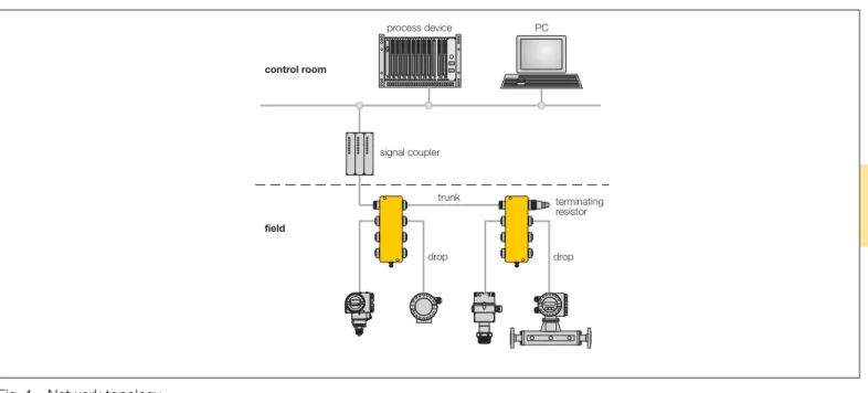
/0407 Hans Turck GmbH & Co.KG • D–45466 Mülheim/Ruhr • Tel. 0208/4952-0 • Fax 0208/4952-264 • E-Mail: [email protected] • Internet: www.turck.comPROFIBUS-PA – bus physics With the publication of the international standard IEC 61158-2 in October 1994, a suitable transmission technology was determined and internationally specifi ed for the application areas of PROFIBUS-PA and FOUNDATION fi eldbus™. This was later integrated into the European stan- dards as EN 61158-2.
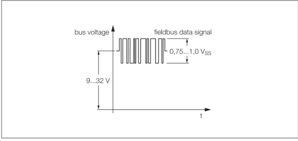
Both systems comply with IEC 61158-2 and operate on the voltage mode with a transmission speed of 31.25 kBit/s. In this way the data packages are modulated onto the supply voltage for the fi eldbus station and transmitted via a shielded two- wire cable (see Fig. 1).
These bus physics offer a decisive advantage: fi eldbus communication and power supply of the bus station can be implemented using a single cable. These bus physics lead to enhanced operational safety and lower costs compared with the conventional fi eldbus solution used up to this point with its additional wiring effort.
Fig. 1 Transmission of data packages to IEC 61158-2
Data transmission digital, bit synchronous, Manchester coding Transmission speed 31.25 kBit/s, voltage mode
Data security preamble, fault protected start and end delimiter
Cable shielded and twisted 2-wire cable
Remote supply of the stations optionally via signal cables
Protection classes intrinsically safe (Ex ia/ib or Ex nL), increased safe (Ex e or Ex nA) and explosion protected (EEx d/m/p/q)
Topology spur and tree topologies; also in combination Number of stations up to 32 stations per cable segment
Repeater can be extended with a maximum of 4 repeaters 9...32 V
t 0,75...1,0 VSS
bus voltage fieldbus data signal
Characteristic features of the IEC 61158-2 transmission physics
DP fi eldbus. The segment coupler adapts the RS485 transmission physics to the transmission physics determined in IEC 61158-2. If the DP segment operates with a higher speed, an additional link is required.
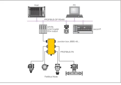
The segment coupler for non-explosion hazardous applications provides enough power for a suffi cient number of fi eldbus stations (Fig. 2).
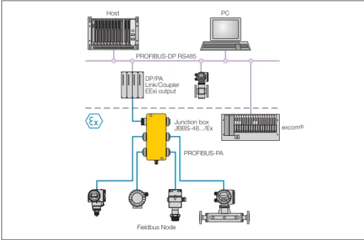
A coupler with an intrinsically-safe output is necessary for use in explosion-hazar- dous areas. This, however, reduces the output power and the number of connec- table bus stations. Only a few stations can be powered (Fig. 3) due to the current consumption of the bus stations.
Fig. 2 Topology – PROFIBUS PA in the non-explosion hazardous area with DP/PA coupler
Fig. 3 Topology – PROFIBUS-PA in the explosion hazardous area with DP/PA couplers with intrinsically safe outputs
excom®
PTB 00 ATEX 0000 XPTB 00 ATEX 0000 XPTB 00 ATEX 0000 XPTB 00 ATEX 0000 X PTB 00 ATEX 0000 X PTB 00 ATEX 0000 X PTB 00 ATEX 0000 XPTB 00 ATEX 0000 X PTB 00 ATEX 0000 XPTB 00 ATEX 0000 X PTB 00 ATEX 0000 X PTB 00 ATEX 0000 X PTB 00 ATEX 0000 X PTB 00 ATEX 0000 X PTB 00 ATEX 0000 X PTB 00 ATEX 0000 X PTB 00 ATEX 0000 X PTB 00 ATEX 0000 X
Fieldbus Node DP/PA Link/Coupler EExi output PROFIBUS-DP RS485
PROFIBUS-PA Junction box JBBS-48...
excom®
PTB 00 ATEX 0000 XPTB 00 ATEX 0000 XPTB 00 ATEX 0000 XPTB 00 ATEX 0000 X PTB 00 ATEX 0000 X PTB 00 ATEX 0000 X PTB 00 ATEX 0000 XPTB 00 ATEX 0000 X PTB 00 ATEX 0000 XPTB 00 ATEX 0000 X PTB 00 ATEX 0000 X PTB 00 ATEX 0000 X PTB 00 ATEX 0000 X PTB 00 ATEX 0000 X PTB 00 ATEX 0000 X PTB 00 ATEX 0000 X PTB 00 ATEX 0000 X PTB 00 ATEX 0000 X
Host
Fieldbus Node DP/PA Link/Coupler EExi output PROFIBUS-DP RS485
PROFIBUS-PA PC
Junction box JBBS-48.../Ex
8
/0407 Hans Turck GmbH & Co.KG • D–45466 Mülheim/Ruhr • Tel. 0208/4952-0 • Fax 0208/4952-264 • E-Mail: [email protected] • Internet: www.turck.comMBD48-T415/Ex
120 m üï ïý ïï þ
excom®
PTB 00 ATEX 0000 XPTB 00 ATEX 0000 XPTB 00 ATEX 0000 XPTB 00 ATEX 0000 X PTB 00 ATEX 0000 X PTB 00 ATEX 0000 X PTB 00 ATEX 0000 XPTB 00 ATEX 0000 X PTB 00 ATEX 0000 XPTB 00 ATEX 0000 X PTB 00 ATEX 0000 X PTB 00 ATEX 0000 X PTB 00 ATEX 0000 X PTB 00 ATEX 0000 X PTB 00 ATEX 0000 X PTB 00 ATEX 0000 X PTB 00 ATEX 0000 X PTB 00 ATEX 0000 X
MBD48-T415/Ex MBD48-T415/Ex
DP/PA Coupler PROFIBUS-DP RS485
EEx e Zone 1
Host
Trunk in Trunk out EEx e
Zone 0
PC
Segment out PROFIBUS-PA
Multibarrier
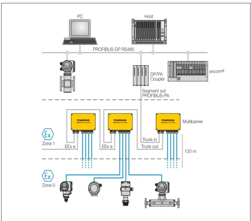
Fig. 4 Topology – PROFIBUS-PA in the explosion-hazardous area with multibarriers This situation can be remedied by a to-
pology which is based on the use of main line (trunk line) featuring “enhanced safety”
and intrinsically safe outputs.
This is where the multibarrier is employed, permitting a current of up to 10 A in the trunk line area, and when connected in series, supplying up to intrinsically safe 32 stations in the explosion-hazardous area.
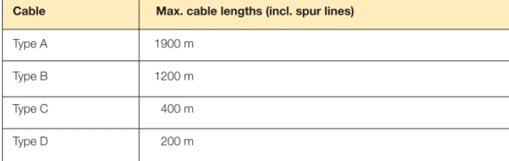
Fig. 4 shows the typical confi guration of a PROFIBUS-PA network with TURCK multibarriers. The number of multibarriers which can be switched in and the maxi- mum cable lengths depend on the output power of the DP/PA coupler and on the cable type.
TURCK recommends the long-distance
cable FBY.../LD (see page 89) for the
trunk line; for the outputs the standard
cable FBY.../SD is recommended (see
page 88).
Zone 0 Zone 1 Zone 2 Zone 0 Zone 1 Zone 2 Zone 0 Zone 1 Zone 2
conform to FISCO conform to EN 50020 circuits Non-Ex
conform to area
EEx ia EEx ia EEx ib EEx ib
Junction boxes without short-circuit protection
JBBS...M... — — — — — — ✔ ✔ — ✔ ✔ ✔
JBBS...E... — — — — — — ✔ ✔ — ✔ ✔ ✔
JBBS...T... — — — — — — ✔ ✔ — ✔ ✔ ✔
Junction boxes with short-circuit protection
JBBS...SC...M... — — — — — — ✔ ✔ — — ✔ ✔
JBBS...SC...E... — — — — — — ✔ ✔ — — ✔ ✔
JBBS...SC...T... — — — — — — ✔ ✔ — — ✔ ✔
Ex junction boxes without short-circuit protection
JBBS...M.../Ex ✔ ✔ ✔ ✔ ✔ ✔ ✔ ✔ — ✔ ✔ ✔
JBBS...E.../Ex ✔ ✔ ✔ ✔ ✔ ✔ ✔ ✔ — ✔ ✔ ✔
JBBS...T.../Ex ✔ ✔ ✔ ✔ ✔ ✔ ✔ ✔ — ✔ ✔ ✔
Ex junction boxes with short-circuit protection
JBBS...SC...M.../Ex ✔ ✔ ✔ ✔ ✔ ✔ ✔ ✔ — ✔ ✔ ✔
JBBS...SC...E.../Ex ✔ ✔ ✔ ✔ ✔ ✔ ✔ ✔ — ✔ ✔ ✔
JBBS...SC...T.../Ex ✔ ✔ ✔ ✔ ✔ ✔ ✔ ✔ — ✔ ✔ ✔
Ex junction boxes for DIN hat-rail mounting
JRBS...1) ✔ ✔ ✔ ✔ ✔ ✔ ✔ ✔ — ✔ ✔ ✔
Multibarriers
MBD...2) ✔ ✔ ✔ ✔ ✔ ✔ ✔ ✔ — ✔ ✔ ✔
Temperature transmitters1)
KMU-40Ex/1GD ✔ ✔ ✔ ✔ ✔ ✔ ✔ ✔ ✔ ✔ ✔ ✔
KMU-40Ex/3G — — — — — — ✔ ✔ — — ✔ ✔
Terminating resistors
RS...-TR — — — — — — — — — — — ✔
Ex terminating resiators
RS...-TR/Ex ✔ ✔ ✔ ✔ ✔ ✔ ✔ ✔ ✔ ✔ ✔ ✔
Passive equippment without electronics (cable,
connectors, fl anges ...3) ✔ ✔ ✔ ✔ ✔ ✔ ✔ ✔ ✔ ✔ ✔ ✔
✔
= Use possible
— = Use not possible
1) Use only permitted when installed in an additional housing (minimum IP54 degree of protection)
2) Equipment with differing protection classes – only the EEx i outputs have
FNICO Entity
CAUTION
Intrinsically safe equipment,
10
/0407 Hans Turck GmbH & Co.KG • D–45466 Mülheim/Ruhr • Tel. 0208/4952-0 • Fax 0208/4952-264 • E-Mail: [email protected] • Internet: www.turck.com2
The operating principle of the MBD48- T415/Ex multibarrier is physically based on IEC 61158-2. The use of multibarriers increases the number of fi eldbus stations in the PROFIBUS-PA network to a maxi- mum of 32 fi eld devices.
This high number of stations is achieved by enhanced safety of the fi eldbus supply which can be looped through from multi- barrier to multibarrier. The fi eldbus stations in zone 0 are supplied with power via the four intrinsically safe outputs of each multibarrier device.
User benefi ts
The user can expect substantial cost ad- vantages due to the possibility of cascad- ing the multibarriers in a single segment in the explosion hazardous area, thus fully exploiting the entire function range of the bus systems.
All fi eldbus devices can be operated in a single fi eldbus segment in the explo- sion hazard area. Thus, the costs for an additional bus coupler or a segment card as well as their integration and parameter defi nition are eliminated. An additional trunk line and the wiring material is also spared.
The supply of power to the multibarriers is implemented via the bus which means that an additional power cable is not required.
Installation in the explosion hazard- ous area
The area of application to ATEX is II 2 (1 GD) G EEx m e [ia] IIC T4.
Due to its EEx e protection rating, the MBD48-T415/Ex multibarrier can be installed in zone 1 (II 2 G) according to 94/9/EC (ATEX 95a).
Use in explosion hazardous areas with explosion protection group IIC – in con- junction with temperature class T4 – is the standard in the process industry.
Within zone 1, the MBD48-T415/Ex is connected via a cable and connections with enhanced safety (EEx e) to the main line (trunk line) of a fi eldbus conform to
Intrinsic safety and galvanic isolation between all outputs
For safety reasons, galvanic isolation of signals plays a decisive role in the Ex area.
The multibarrier provides four intrinsically safe and galvanically isolated outputs. The complete galvanic isolation exists between the main bus cable (trunk line) and the out- put circuits as well as between all of the four individual output circuits.
Galvanic isolation of intrinsically safe cir- cuits, as demanded by the industry, particularly for zone 0, is thus provided.
Potential transfers and potential equaliza- tion currents are thus reduced and safe data transmission is guaranteed.
Operational safety
Operational safety of the bus system must be guaranteed should a bus station fail or malfunction. The four outputs of the multibarrier each supply an output current of max. 40 mA.
If a short-circuit occurs on a fi eldbus sta- tion, the integrated short-circuit protection comes into play. Only the affected output will be shut down, the main line and the other outputs of the fi eldbus segment remain operational. The short-circuit is indicated for each channel by a red LED inside the housing.
Industrially suitable housing
Industrial environmental conditions are fre- quently harsh and aggressive. Therefore, a housing suitable for these conditions is necessary. The enhanced IP66 degree of protection and the special housing mate- rial (die-cast aluminium) – in conjunction with the encapsulated module electronics – meet these demands and provide a high level of operational safety. Direct installa- tion of a multibarrier in the system is thus unproblematic.
The EEx e cable glands guarantee safe and quick connection technology in conjunction with the high-quality cage clamps.
Shield terminals are capacitively connec- ted to the housing potential in order to divert possible interference voltages on the cable shield. The riveted ground bolt
Functions which supplement the standard
• FISCO conformity
The FISCO model has been developed for the supply of power to fi eldbus stations in the Ex area by the PTB in cooperation with renowned
manufacturers. FISCO stands for Fieldbus Intrinsically Safe Concept.
It is intended to simplify the verifi cation of intrinsic safety of fi eldbus systems.
Intrinsically safe networks can be confi gured without highly complex calculations, and also expanded and operated without system certifi cation.
The outputs of the multibarrier conform to the demands of an Ex current supply and also conform to FISCO.
• Switch-in terminating resistors Data transmission on bus cables is frequently infl uenced by signal refl ection, which can occur when the bus ends are not terminated. The fi eldbus must be provided with a terminating resistor at both ends in order to avoid signal refl ection. The multibarrier is provided with an integrated terminating resistor, which should be activated, when the multibarrier is connected as the last device on the main bus line (trunk line).
• Climatic compensation
In regions subject to large temperature and air-humidity variations, it is possible that formation of condensation or a build-up of water within the housing is possible during operation. In order to avoid this, the multibarrier is fi tted on the cable connection end with a pressure equalisation element to avoid the build-up of condensation.
The pressure equalisation element features IP67 degree of protection and guarantees continuous and reliable ventilation and venting of the
multibarriers. The ePTFE diaphragm in
the centre of the gland features a very
high water ingress pressure and repels
oil. Even 100 % of salt crystals are kept
out.
12
/0407 Hans Turck GmbH & Co.KG • D–45466 Mülheim/Ruhr • Tel. 0208/4952-0 • Fax 0208/4952-264 • E-Mail: [email protected] • Internet: www.turck.comMultibarrier, 4-channel MBD48-T415/EX
G
Entity and FISCO compliance acc.
to IEC TS 60079-27
G
Galvanic isolation between the EEx i outputs and the EEx e bus line, as well as between the EEx i outputs
G
Powder-coated die-cast aluminium housing
G
Pressure compensation element for protection against condensation water
G
Connection of the housing potential via an M5 x 1 bolt
G
Temperature range: -20...+70 °C (-4...+158 °F)
G
Integrated terminating resistor (switch-in)
G
Cable shielding: capacitive connec- tion to housing potential
G
Output data: 10 V/40 mA (short-cir- cuit proof)
The four-channel multibarrier MBD48-T415/
EX is designed to connect a large number of field devices to the PROFIBUS-PA (acc.
to IEC 61158-2).
The number of connectable field devices to the multibarrier depends on the current consumption of the individual devices. Up to 32 EEx i field devices can be connected to the bus. This extension capacity is achieved by means of the EEx e fieldbus supply which is fed through from multi- barrier to multibarrier.
The inputs and outputs of the trunk line fea- ture increased safety (EEx e) whereas the
outputs to the field devices feature intrinsic safety, type EEx i.
The multibarrier is equipped with a selec- table bus terminating resistor. The switch is integrated in the housing on the board.
The multibarrier is equipped with four LEDs located on the printed circuit board inside the housing to provide short-circuit indica- tions separately for each channel.
Due to complete galvanic isolation, trunk- line to EEx i-outputs and between EEx i- outputs, a safe operation is guaranteed.
+
+ 1
S
S S1
+ S
+ S
+ S
+ S
Trunk In
Trunk Out 2
3
4
1 nF
1 nF
1 nF
1 nF
1 nF RD
RD
RD
RD
2
Multibarrier, 4-channel MBD48-T415/EX
Dimensions
Trunk-line
Output
Current consumption
90
160 260
EEx e S S + +
EEx i
S1 S2 S3 S4
+ S + S + S + S
0 50 16 100 150 200 250 300 mA
18 20 22 24 26 28 30 32 V Imax
Imin
Type MBD48-T415/EX
Ident-No. 6611270
Fieldbus standard IEC 61158-2
Operating voltage (Pwr) 16...32 VDC
Current self-consumption ð 40 mA
Galvanic isolation input circuits (EEx e) to output circuits (EEx i)
for 253 Vrms; output circuits (EEx i) to each other for 60 Vrms
Output circuits
Output current ð 40 mA
Output voltage ï 10 VDC
Short-circuit protection ð 45 mA
Indication
Short-circuit message 4 x red
Ex approval acc. to conformity certificate PTB 04 ATEX 2021
Max.output voltage Uo ð 14.3 V
Max. output current Io ð 268 mA
Max. output power Po ð 958 mW
Internal resistance Ri 53.3 ò
Internal inductance/ capacitance Li/Ci negligible
Typical curve linear
Marking of the device É II 2(1 G/D)G EEx m e [ia] IIC T4
FISCO / Entity multibarrier
Connection cable glands
Segment IN 1 x M20 x 1.5 (Ø 10...14 mm); black
Segment OUT 1 x M20 x 1.5 (Ø 10...14 mm); black
Drop line 4 x M20 x 1.5 (Ø 5...9 mm); blue
Connection cross-section 2.5 mm2
Earthing bolt M5 x 1
Protection degree IP66
Ambient temperature -20...+70 °C
Relative humidity ð 95 %, non condensing
Housing material powder-coated die-cast aluminium
Housing colour black/yellow
Dimensions 260 x 160 x 90 mm
Connection mode wall mounting
14
/0407 Hans Turck GmbH & Co.KG • D–45466 Mülheim/Ruhr • Tel. 0208/4952-0 • Fax 0208/4952-264 • E-Mail: [email protected] • Internet: www.turck.comFieldbus display, 3-channel FD-48-T317/EX
G
Entity and FISCO compliance acc.
to IEC TS 60079-27
G
Digital fieldbus display for mapping of process values
G
Powder-coated die-cast aluminium housing
G
Connection of the housing potential via external earthing
The three-channel digital indicator FD-48- T317/EX displays the process information of the fieldbus nodes belonging to PROFIBUS-PA-Network.
The device scans the programmed fieldbus addresses and displays their values. Para- meterisation is keyword protected and im- plemented with the front keypad.
Adjustments can be made for each channel separately. The process value of the ac- tuator i.e. sensor is displayed as a 5 digit number and the process value status via limiting value tags.
Apart from a measuring value indicator, the display contains a 41-segment bargraph for trend monitoring, which can be scaled sep- arately from the display value.
The indicator FD-48-T317/EX performs as a
"listener", i.e. initialisation by the master is not required (integration via software redun- dant) and it doesn't appear in the network as a node with an own address.
The device is supplied with energy by the
fieldbus (< 10 mA) and can be applied in Ex
areas up to temperatures of the class T6.
2
Fieldbus display, 3-channel FD-48-T317/EX
Dimensions
103 71
125 140
140
Type FD-48-T317/EX
Ident-No. 6901315
Fieldbus standard IEC 61158-2
Operating voltage (Pwr) 9...30 VDC
Current self-consumption ð 10 mA
Indication
Display LCD, five-digit 7-segment display
Ex approval acc. to conformity certificate TÜV 07 ATEX 553588
Max. input voltage Ui ð 30 V
Max. input current Ii ð 660 mA
Max. input power Pi ð 1600 mW
Internal inductance/ capacitance Li/Ci negligible
Marking of the device É II 2(1) G EEx ia IIC T6 resp. T5
É II 2 D IP65 T70°C
FISCO / Entity Fielddevice
Connection cable glands
Connection cross-section 2.5 mm2
Protection degree IP66
Ambient temperature -10...+60 °C
Housing material powder-coated die-cast aluminium
Housing colour black
Dimensions 140 x 140 x 71 mm
Connection mode wall mounting
16
/0407 Hans Turck GmbH & Co.KG • D–45466 Mülheim/Ruhr • Tel. 0208/4952-0 • Fax 0208/4952-264 • E-Mail: [email protected] • Internet: www.turck.comThe KMU-40Ex/3G and KMU-40Ex/1GD transmitters are intended for connection to the PROFIBUS-PA. The unique conversion function enables automatic switch-over between both protocols. The bus connec- tion is free of polarity consid-erations.
Applications:
• Linear temperature measurements with resistance thermometers or
thermocouples
• Differential, average value or redundant temperature measurements with resis- tance thermometers or thermocouples
General technical data
Accuracy (general values)
Input type Absolute accuracy Temperature coeffi cient
– All ≤ ± 0.05 % of measured value ≤ ± 0.002 % of measured value/°C Accuracy (fundamental values)
Input type Fundamental accuracy Temperature coeffi cient
– Pt100/Pt1000 ≤ ± 0.1 °C ≤ ± 0.002 °C/°C
– Ni100 ≤ ± 0.15 °C ≤ ± 0.002 °C/°C
– Cu10 ≤ ±1.3 °C ≤ ± 0.02 °C/°C
– Linear resistor ≤ ± 0.05 Ω ≤ ± 0.002 Ω/°C
– Voltage ≤ ± 10 µV ≤ ± 0.2 µV/°C
– Thermocouple type: E, J, K, L, N, T, U ≤ ± 0.5 °C ≤ ± 0.010 °C/°C
– Thermocouple type: B, R, S, W3, W5 ≤ ± 1 °C ≤ ± 0.025 °C/°C Electrical input data (resistance thermometer and linear resistance)
Typ e Minimum value Maximum value Standard/remarks
– Pt25...Pt1000 -200 °C +850 °C IEC 60751/JIS C 1604
– Ni25...Ni1000 -60 °C +250 °C DIN 43760
– Cu10...Cu1000 -50 °C +200 °C a = 0.00427
– Linear resistor 0 Ω 10 kΩ –
– Potentiometer 0 Ω 100 kΩ –
Conductor resistance per conductor 50 Ω Sensor current nom. 0.2 mA Electrical input data (thermocouple and mV input)
Type Minimum value Maximum value Standard
– B +400 °C +1820 °C IEC 584
– E -100 °C +1000 °C IEC 584
– J -100 °C +1200 °C IEC 584
– K -180 °C +1372 °C IEC 584
– L -200 °C +900 °C DIN 43710
– N -180 °C +1300 °C IEC 584
– R -50 °C +1760 °C IEC 584
– S -50 °C +1760 °C IEC 584
– T -200 °C +400 °C IEC 584
– U -200 °C +600 °C DIN 43710
– W3 0 °C +2300 °C ASTM E988-90
– W5 0 °C +2300 °C ASTM E988-90
– Ext. cold junction compensation -40 °C +135 °C IEC 60751
– mV input -800 mV +800 mV –
Cold junction compensation (CJC) < ± 0.5 °C Sensor fault recognition yes
Short-circuit recognition < 3 mV
• Linear resistance, compensator and bipolar mV measurements
The 24 bit A/D converter guarantees a high resolution.
Both transmitters can be mounted in a type B terminal housing (DIN standard).
Whereas the KMU-40Ex/3G is used in
the explosion hazardous area in zone 2,
the KMU-40Ex/1GD can also be used
in zones 0, 1 and 2 in intrinsically safe
circuits.
2
Type KMU-40Ex/3G
Ident-No. 7506619
Operating voltage (Pwr) 9...32 VDC
Current consumption < 11 mA
Insulation voltage – test/operation 1500 VAC/50 VAC
Signal to noise ratio > 60 dB
Response time (programmable) 1...60 s
Refresh time < 400 ms
Execution time (PID controller) < 200 ms
Execution time (analogue input) < 50 ms
Signal resolution (input) 24 Bit
Calibration temperature 20...28 °C Ex approval according to
EC type examination KEMA 05 ATEX 1031 X
– U0 5.71 V
– I0 8.4 mA
– P0 12 mW
– C0/L0 40 µF/200 mH
Marking of device É II 3 G EEX nA [L] IIC T4...T6 FM, UL and CSA approval Class I, Div. 2, Gr. A, B, C, D; Class I, Zone 2, NIFW/FNICO
Output
PROFIBUS-PA protocol standard EN 50170, Vol. 2 PROFIBUS-PA function blocks 2 × analogue
PROFIBUS-PA address (ex-works) 126
Housing
Housing material Cycoloy
Housing and terminal degree of protection IP68 or IP00 (IEC 60529/EN 60529)
Dimensions/weight Ø 44 × 20.2 mm/55 g Vibration resistance to IEC 60068-2-6, Test FC
Relative humidity < 95 % (non-condensating)
Ambient temperature -40...+85 °C (-40...+185 °F)
• Confi guration via PROFIBUS-PA with Siemens Simatic
®PDM
®, ABB Melody/
Harmony, Honeywell Ax and Metso DNA software
• Suitable for use in zone 2
• Type B terminal housing General information:
see page 16 Wiring diagrams:
see page 19
20,2 ø 6,3
ø 44
M4 x 30
18
/0407 Hans Turck GmbH & Co.KG • D–45466 Mülheim/Ruhr • Tel. 0208/4952-0 • Fax 0208/4952-264 • E-Mail: [email protected] • Internet: www.turck.com Type KMU-40Ex/1GDIdent-No. 7506618 Operating voltage (in FISCO installations) 9...30 VDC (9...17,5 VDC)
Current consumption < 11 mA
Insulation voltage – test/operation 1500 VAC/50 VAC
Signal to noise ratio > 60 dB
Response time (programmable) 1...60 s
Refresh time < 400 ms
Execution time (PID controller) < 200 ms
Execution time (analogue input) < 50 ms
Signal resolution (input) 24 Bit
Calibration temperature 20...28 °C Ex approval according to
EC type examination KEMA 05 ATEX 1030
U0/I0/P0/C0/L0 5.71 V/8.4 mA/12 mW/40 µF/200 mH
Zone 0, Div. 1, EEx ia IIC, Entity/FISCO Barriers with P0 < 0.84 W Barriers with P0 < 1.3 W FISCO (IIB) FISCO (IIC)
– Ui 30 VDC 30 VDC 17.5 VDC 15 VDC
– Ii 120 mA 300 mA 250 mA free 1)
– Pi 0.84 W 1.3 W 2.0 W free 1)
– Li/Ci 1 µH/2.0 nF 1 µH/2.0 nF 1 µH/2.0 nF 1 µH/2.0 nF Zone 1, Div. 2, EEx ib IIC, Entity/FISCO Barriers with P0 < 5.32 W FISCO segment coupler
– Ui 30 VDC 17.5 VDC
– Ii 250 mA free 1)
– Pi 5.32 W free 1)
– Li/Ci 1 µH/2.0 nF 1 µH/2.0 nF
Marking of device É II 2(1) GD EEx ib [ia] IIC T1...T6
FM, UL and CSA approval Class I, Div. 1, Gr. A, B, C, D; Class I, Zone 0/1, Gr. IIC; Class I, Div. 2, Gr. A, B, C, D Output
PROFIBUS-PA protocol standard EN 50170, Vol. 2 PROFIBUS-PA function blocks 2 × analogue PROFIBUS-PA address (ex-works) 126
Housing
Housing material Cycoloy
Housing and terminal degree of protection IP68 or IP00 (IEC 60529/EN 60529)
Dimensions/weight Ø 44 × 20.2 mm/55 g Vibration resistance to IEC 60068-2-6, Test FC
Relative humidity < 95 % (non-condensating)
Ambient temperature -40...+85 °C (-40...+185 °F)
1) Transducers can be freely mounted taking consideration of Li and Ci. Current and power are limited by the FISCO model.
• Confi guration via PROFIBUS-PA with Siemens Simatic
®PDM
®, ABB Melody/
Harmony, Honeywell Ax and Metso DNA software
• Suitable for use in zone 0, 1 and 2, 20, 21, 22
• Type B terminal housing General information:
see page 16 Wiring diagrams:
see page 19
20,2 ø 6,3
ø 44
M4 x 30
2
3
4 5
6 3
4 5
6 3
4 5
6
2 1 3
4 5
6
3
4 5
6
+
2 + 3
4 5
6
1 +
3
4 5
6
+
3
4 5
6
+
3
4 5
6 3
4 5
6 3
4 5
6 3
4 5
6
Resistance thermometer, 2-wire Resistance thermometer, 3-wire Resistance thermometer, 4-wire 2 × resistance thermometer, 2-wire
Thermcouple with internal cold junction compensation
2 × thermcouple with internal cold junction compensation
Thermcouple with external cold junction compensation
mV input
Resistor, 2-wire Resistor, 3-wire Resistor, 4-wire Potentiometer, 3-wire
1 2
Output
6 5
4 3 1
2
1 2
FOUNDATION
PROFIBUS converterA/D
function blocks
FOUNDATION
fieldbus protocol
function
blocks PROFIBUS protocol
automatic bus termination
Ex-circuit,
KMU-40/1GDonly bus connection
internal CJC
CPU
Block diagram
20
/0407 Hans Turck GmbH & Co.KG • D–45466 Mülheim/Ruhr • Tel. 0208/4952-0 • Fax 0208/4952-264 • E-Mail: [email protected] • Internet: www.turck.com3
TURCK offers junction boxes in various designs for the distribution of energy and data.
The junction boxes differ in the number of channels, the housing style and special features such as integrated short-circuit protection, switch-in terminating resistor and selectable shielding concept.
The following junctions are available as standard versions.
Special solutions are available on request.
IP67 junction boxes with or without short-circuit protection
(1, 4 and 6 channels)
• Explosion-protected junctions (for use in zone 1 or 2, distribution of EEx ia signals in zone 0)
• Standard junctions (non-Ex)
• IP67 degree of protection
• Switch-in terminating resistor
• Selectable shielding concept (hard-wired or capacitive grounding)
• Active and passive types
• Pressure compensation element to prevent water condensation
• Housing material: powder-coated die-cast aluminium
(4 and 6-channel type)
• Connection technology: stainless steel fl ange connectors 7/8“, M12 or cage- clamp terminals
• Cable glands: plastic, stainless steel, nickel-plated brass, EMC
• Temperature range: -25 °C ... +70 °C
IP20 junction boxes with or without short-circuit protection
(4 , 6, 8 and 12 channels)
• Suitable for the explosion hazardous and the safe area
• For use in zone 1 or 2, distribution of EEx ia signals in zone 0
• IP20 degree of protection
• Switch-in terminating resistor
• Selectable shielding concept (hard-wired or capacitive grounding)
• Active and passive types
• Housing material: aluminium
• Connection technology:
cage-clamp terminals or removable screw terminals
• Temperature range: -40 °C ...+70 °C
CAUTION
Explosion Danger!
The EC type test examina- tion certifi cate and the manufacturer’s declaration
of conformity must be observed.
It is essential that the “special conditions” in
the EU type test certifi cate are observed.
Junction boxes, which have
been used in non intrinsically
safe applications, may not
subsequently be used in
intrinsically safe applications.
22
/0407 Hans Turck GmbH & Co.KG • D–45466 Mülheim/Ruhr • Tel. 0208/4952-0 • Fax 0208/4952-264 • E-Mail: [email protected] • Internet: www.turck.comIP67 junction box, 4-channel JBBS-48SC-T415/3G
G
Entity and FNICO compliance acc.
to IEC TS 60079-27
G
Mounting possible in zone 2
G
Junction box for wall mounting with PVC cable glands M20 x 1.5
G
Powder-coated die-cast aluminium housing
G
Pressure compensation element for protection against condensation water
G
Connection of the housing potential via an M5 x 1 bolt
G
With drop line short-circuit protec- tion
G
Integrated terminating resistor (switch-in)
G
Cable shielding: capacitive or direct connection to housing potential se- lectable via switch
G
Isolated support terminal for optio- nal protective conductor incorpo- rated in cable
The 4-channel Ex junction box, type JBBS-48SC-T415/3G is designed for the PROFIBUS-PA.
The junction box features an adjustable short-circuit limit. The max. current limita- tion is selected for all channels via a rotary switch. The following values can be se- lected: 30, 35, 45 and 60 mA.
The housing is made of robust die-cast alu- minium and features protection degree IP67.
The junction box is equipped with a select- able bus terminating resistor.
The according switch is integrated in the housing on the board.
To avoid condensation build-up in the hous- ing, the devices are equipped with a con- densate drain.
The shield is capacitively coupled to the housing potential. A switch for direct cou- pling of the shield and housing is imple- mented.
Attention: Sufficient equipotential bonding of the installation must be ensured. The de- vice is connected via the M5 x 1 bolt of the housing to the system’s potentializer.
1 2 34
1 2 34 1µF 100 W
Case ground n.c.
S+
P1
n.c.
S+
S0
12 3 4 n.c.
S+
S1
1 2 3 4 n.c.
S+
S3
1 2 3 4
n.c.
S+
S2
12 3 4
n.c.S +
S4
Segment IN Segment OUT
3
IP67 junction box, 4-channel JBBS-48SC-T415/3G
Dimensions
Pin configuration
12264 36
150 138
172 45
1 2 3 4 1 = n.c.
2 = shield 3 = + 4 =
Type JBBS-48SC-T415/3G
Ident-No. 6611416
Fieldbus standard IEC 61158-2
Operating voltage (Pwr) 12...32 VDC
Current self-consumption ð 7 mA
Voltage dip ð 0.3 V
Short-circuit protection ð 30, 35, 45, 60 mA
Indication
Operational readiness 1 x green
Short-circuit message 4 x red
Ex approval acc. to conformity certificate PTB 07 ATEX 2017 X
Entity Parameter
Max.output voltage Uo ð 32 V
Max. output current Io ð 63 mA
Max. output power Po ð 2100 mW
Max. input voltage Ui ð 32 V
Max. input current Ii ð 3000 mA
FNICO parameter according to IEC TS 60079-27
Max.output voltage Uo ð 17.5 V
Max. output current Io ð 63 mA
Max. output power Po ð 1100 mW
Max. input voltage Ui ð 17.5 V
Max. input current Ii ð 513 mA
Max. input power Pi ð 7250 mW
External inductances/capacitances Li/Ci trunk (in/out):
negligible / ð 5.00 nF per field current circuit:
negligible / ð 0.47 nF æ field current circuits:
negligible / ð 5.00 nF
Marking of the device É II 3 G Ex nA II T4
É II 3 G Ex nA [nL] IIC/IIB T4
FNICO / Entity field device
Connection cable glands
Segment IN 1 x M20 x 1.5 (Ø 6...12 mm)
Segment OUT 1 x M20 x 1.5 (Ø 6...12 mm)
Drop line 4 x M20 x 1.5 (Ø 6...12 mm)
Connection cross-section 2.5 mm2
Earthing bolt M5 x 1
Protection degree IP67
Ambient temperature -25...+70 °C
Housing material powder-coated die-cast aluminium
Housing colour black/yellow
Dimensions 64 x 150 x 45 mm
Connection mode wall mounting
24
/0407 Hans Turck GmbH & Co.KG • D–45466 Mülheim/Ruhr • Tel. 0208/4952-0 • Fax 0208/4952-264 • E-Mail: [email protected] • Internet: www.turck.comIP67 junction box, 6-channel JBBS-48SC-T615/3G
G
Entity and FNICO compliance acc.
to IEC TS 60079-27
G
Mounting possible in zone 2
G
Junction box for wall mounting with PVC cable glands M20 x 1.5
G
Powder-coated die-cast aluminium housing
G
Pressure compensation element for protection against condensation water
G
Connection of the housing potential via an M5 x 1 bolt
G
With drop line short-circuit protec- tion
G
Integrated terminating resistor (switch-in)
G
Cable shielding: capacitive or direct connection to housing potential se- lectable via switch
G
Isolated support terminal for optio- nal protective conductor incorpo- rated in cable
The 6-channel Ex junction box, type JBBS-48SC-T615/3G is designed for the PROFIBUS-PA.
The junction box features an adjustable short-circuit limit. The max. current limita- tion is selected for all channels via a rotary switch. The following values can be se- lected: 30, 35, 45 and 60 mA.
The housing is made of robust die-cast alu- minium and features protection degree IP67.
The junction box is equipped with a select- able bus terminating resistor.
The according switch is integrated in the housing on the board.
To avoid condensation build-up in the hous- ing, the devices are equipped with a con- densate drain.
The shield is capacitively coupled to the housing potential. A switch for direct cou- pling of the shield and housing is imple- mented.
Attention: Sufficient equipotential bonding of the installation must be ensured. The de- vice is connected via the M5 x 1 bolt of the housing to the system’s potentializer.
1 2 3 4
1 2 3 4 1µF 100 W
case ground n.c.
S+
P1
n.c.
S+
S0
1 2 3 4 n.c.
S+
S1
1 2 3 4 n.c.
S+
S5
1 2 3 4
n.c.
S+
S2
1 2 34
n.c.
S+
S6 1
2 3 4 n.c.
S+
S3
1 2 3 4
n.c.
S+
S4
Trunk In Trunk Out
3
IP67 junction box, 6-channel JBBS-48SC-T615/3G
Dimensions
Pin configuration
12264,0 36,0
185,5 173,5
207 45,0
1 2 3 4 1 = n.c.
2 = shield 3 = + 4 =
Type JBBS-48SC-T615/3G
Ident-No. 6611418
Fieldbus standard IEC 61158-2
Operating voltage (Pwr) 12...32 VDC
Current self-consumption ð 7 mA
Voltage dip ð 0.3 V
Short-circuit protection ð 30, 35, 45, 60 mA
Indication
Operational readiness 1 x green
Short-circuit message 6 x red
Ex approval acc. to conformity certificate PTB 07 ATEX 2017 X
Entity Parameter
Max.output voltage Uo ð 32 V
Max. output current Io ð 63 mA
Max. output power Po ð 2100 mW
Max. input voltage Ui ð 32 V
Max. input current Ii ð 3000 mA
FNICO parameter according to IEC TS 60079-27
Max.output voltage Uo ð 17.5 V
Max. output current Io ð 63 mA
Max. output power Po ð 1100 mW
Max. input voltage Ui ð 17.5 V
Max. input current Ii ð 513 mA
Max. input power Pi ð 7250 mW
External inductances/capacitances Li/Ci trunk (in/out):
negligible / ð 5.00 nF per field current circuit:
negligible / ð 0.47 nF æ field current circuits:
negligible / ð 5.00 nF
Marking of the device É II 3 G Ex nA II T4
É II 3 G Ex nA [nL] IIC/IIB T4
FNICO / Entity field device
Connection cable glands
Segment IN 1 x M20 x 1.5 (Ø 6...12 mm)
Segment OUT 1 x M20 x 1.5 (Ø 6...12 mm)
Drop line 6 x M20 x 1.5 (Ø 6...12 mm)
Connection cross-section 2.5 mm2
Earthing bolt M5 x 1
Protection degree IP67
Ambient temperature -25...+70 °C
Housing material powder-coated die-cast aluminium
Housing colour black/yellow
Dimensions 64 x 185.5 x 45 mm
Connection mode wall mounting
26
/0407 Hans Turck GmbH & Co.KG • D–45466 Mülheim/Ruhr • Tel. 0208/4952-0 • Fax 0208/4952-264 • E-Mail: [email protected] • Internet: www.turck.comIP67 junction box, 4-channel JBBS-48SC-E413/3G
G
Entity and FNICO compliance acc.
to IEC TS 60079-27
G
Mounting possible in zone 2
G
Junction box for wall mounting with stainless steel M12 flange connec- tions
G
Powder-coated die-cast aluminium housing
G
Pressure compensation element for protection against condensation water
G
Connection of the housing potential via an M5 x 1 bolt
G
With drop line short-circuit protec- tion
G
Integrated terminating resistor (switch-in)
G
Cable shielding: capacitive or direct connection to housing potential se- lectable via switch
G
Isolated support terminal for optio- nal protective conductor incorpo- rated in cable
SpurS1 Spur
S2
SpurS3 Spur
S4 Segment IN
P1 Segment OUT
S0
GroundCase
The 4-channel Ex junction box, type JBBS-48SC-E413/3G is designed for the PROFIBUS-PA.
The junction box features an adjustable short-circuit limit. The max. current limita- tion is selected for all channels via a rotary switch. The following values can be se- lected: 30, 35, 45 and 60 mA.
The housing is made of robust die-cast alu- minium and features protection degree IP67.
The junction box is equipped with a select- able bus terminating resistor.
The according switch is integrated in the housing on the board.
To avoid condensation build-up in the hous- ing, the devices are equipped with a con- densate drain.
The shield is capacitively coupled to the housing potential. A switch for direct cou- pling of the shield and housing is imple- mented.
Attention: Sufficient equipotential bonding of the installation must be ensured. The de- vice is connected via the M5 x 1 bolt of the housing to the system’s potentializer.
1 2 34
1 2 34 1µF 100 W
Case Ground +
n.c.
S
P1 S0
12 3 4 S1
1 2 3 4 S3
1 2 3 4
S2
12 3 4
S4 n.c.+
S + n.c.
S
+ n.c.
S
+ n.c.
S n.c.+
S
Segment IN Segment OUT
3
IP67 junction box, 4-channel JBBS-48SC-E413/3G
Dimensions
Pin configuration
83 6436
150 138
172 45
M12 x 1 M12 x 1
4
1 3
2 3
2
4 1
Segment in Segment out, Drop
nominal values: 4 A, 300 V 1 = V +
2 = n.c.
3 = V 4 = shield
Type JBBS-48SC-E413/3G
Ident-No. 6611408
Fieldbus standard IEC 61158-2
Operating voltage (Pwr) 12...32 VDC
Current self-consumption ð 7 mA
Voltage dip ð 0.3 V
Short-circuit protection ð 30, 35, 45, 60 mA
Indication
Operational readiness 1 x green
Short-circuit message 4 x red
Ex approval acc. to conformity certificate PTB 07 ATEX 2017 X
Entity Parameter
Max.output voltage Uo ð 32 V
Max. output current Io ð 63 mA
Max. output power Po ð 2100 mW
Max. input voltage Ui ð 32 V
Max. input current Ii ð 3000 mA
FNICO parameter according to IEC TS 60079-27
Max.output voltage Uo ð 17.5 V
Max. output current Io ð 63 mA
Max. output power Po ð 1100 mW
Max. input voltage Ui ð 17.5 V
Max. input current Ii ð 513 mA
Max. input power Pi ð 7250 mW
External inductances/capacitances Li/Ci trunk (in/out):
negligible / ð 5.00 nF per field current circuit:
negligible / ð 0.47 nF æ field current circuits:
negligible / ð 5.00 nF
Marking of the device É II 3 G Ex nA II T4
É II 3 G Ex nA [nL] IIC/IIB T4
FNICO / Entity field device
Connection M12 flange connection
Segment IN 1 x M12 - male connector
Segment OUT 1 x M12 - female connector
Drop line 4 x M12 - female connector
Earthing bolt M5 x 1
Protection degree IP67
Ambient temperature -25...+70 °C
Housing material powder-coated die-cast aluminium
Housing colour black/yellow
Dimensions 64 x 150 x 45 mm
Connection mode wall mounting
28
/0407 Hans Turck GmbH & Co.KG • D–45466 Mülheim/Ruhr • Tel. 0208/4952-0 • Fax 0208/4952-264 • E-Mail: [email protected] • Internet: www.turck.comIP67 junction box, 6-channel JBBS-48SC-E613/3G
G
Entity and FNICO compliance acc.
to IEC TS 60079-27
G
Mounting possible in zone 2
G
Junction box for wall mounting with stainless steel M12 flange connec- tions
G
Powder-coated die-cast aluminium housing
G
Pressure compensation element for protection against condensation water
G
Connection of the housing potential via an M5 x 1 bolt
G
With drop line short-circuit protec- tion
G
Integrated terminating resistor (switch-in)
G
Cable shielding: capacitive or direct connection to housing potential se- lectable via switch
G
Isolated support terminal for optio- nal protective conductor incorpo- rated in cable
SpurS1 Spur
S2
SpurS3 Spur
S4 Segment IN
P1 Segment OUT
S0
GroundCase
SpurS5 Spur
S6
The 6-channel Ex junction box, type JBBS-48SC-E613/3G is designed for the PROFIBUS-PA.
The junction box features an adjustable short-circuit limit. The max. current limita- tion is selected for all channels via a rotary switch. The following values can be se- lected: 30, 35, 45 and 60 mA.
The housing is made of robust die-cast alu- minium and features protection degree IP67.
The junction box is equipped with a select- able bus terminating resistor.
The according switch is integrated in the housing on the board.
To avoid condensation build-up in the hous- ing, the devices are equipped with a con- densate drain.
The shield is capacitively coupled to the housing potential. A switch for direct cou- pling of the shield and housing is imple- mented.
Attention: Sufficient equipotential bonding of the installation must be ensured. The de- vice is connected via the M5 x 1 bolt of the housing to the system’s potentializer.
1 2 3 4
1 2 3 4 1µF 100 W
Case Ground +
n.c.
S
P1 S0
1 2 3 4 S5
1 2 3 4
S6 +
n.c.
S
+ n.c.
S
+ n.c.
S 1
2 3 4 S1
1 2 3 4
S2 +
n.c.
S
+ n.c.
S 1
2 3 4 S3
1 2 3 4
S4 +
n.c.
S
+ n.c.
S Segment INSegment OUT
3
IP67 junction box, 6-channel JBBS-48SC-E613/3G
Dimensions
Pin configuration
8364 36
185,5 173,5
45
207
M12 x 1 M12 x 1
4
1 3
2 3
2
4 1
Segment in Segment out, Drop
nominal values: 4 A, 300 V 1 = V +
2 = n.c.
3 = V 4 = shield
Type JBBS-48SC-E613/3G
Ident-No. 6611410
Fieldbus standard IEC 61158-2
Operating voltage (Pwr) 12...32 VDC
Current self-consumption ð 7 mA
Voltage dip ð 0.3 V
Short-circuit protection ð 30, 35, 45, 60 mA
Indication
Operational readiness 1 x green
Short-circuit message 6 x red
Ex approval acc. to conformity certificate PTB 07 ATEX 2017 X
Entity Parameter
Max.output voltage Uo ð 32 V
Max. output current Io ð 63 mA
Max. output power Po ð 2100 mW
Max. input voltage Ui ð 32 V
Max. input current Ii ð 3000 mA
FNICO parameter according to IEC TS 60079-27
Max.output voltage Uo ð 17.5 V
Max. output current Io ð 63 mA
Max. output power Po ð 1100 mW
Max. input voltage Ui ð 17.5 V
Max. input current Ii ð 513 mA
Max. input power Pi ð 7250 mW
External inductances/capacitances Li/Ci trunk (in/out):
negligible / ð 5.00 nF per field current circuit:
negligible / ð 0.47 nF æ field current circuits:
negligible / ð 5.00 nF
Marking of the device É II 3 G Ex nA II T4
É II 3 G Ex nA [nL] IIC/IIB T4
FNICO / Entity field device
Connection M12 flange connection
Segment IN 1 x M12 - male connector
Segment OUT 1 x M12 - female connector
Drop line 6 x M12 - female connector
Earthing bolt M5 x 1
Protection degree IP67
Ambient temperature -25...+70 °C
Housing material powder-coated die-cast aluminium
Housing colour black/yellow
Dimensions 64 x 185.5 x 45 mm
Connection mode wall mounting