Therefore, an effective flood early warning system should be developed to mitigate flood losses and reduce the effects of floods. However, when developing a flood disaster warning system, limited communication during the occurrence of floods and the availability of power supplies should be taken into account. Thus, by having an effective real-time flood warning system, immediate action can be taken to save lives and minimize the damage caused by the flood disaster.
INTRODUCTION
- Background
- Problem Statement
- Objectives
- Scope of Work
- Flood Disaster in Kelantan, Terengganu, Pahang, Perak and Johor
- Related Work
- Automated Photonics Flood Warning System (Flood-SMS)
- Cooperative Flood Detection using GSMD via SMS
- Gaps Found in the Literature and Way Forward
- Communication Channels used in Disaster Warning
- Comparative Study on Application of 2G-GSM and 3G for SMS Technology
- User Mobility
- Ways to Measure Water Level
- Microcontroller
- Solar Cell
It is practical to have an early warning system that alerts communities to rising water levels, but there are significant shortcomings that need to be improved. Thus, Chapter 2 discusses how this project relates to the work of others and what can be improved based on the identified gaps and discrepancies in the literature. This section discusses how this research project relates to the work of others and what can be improved based on the identified gaps in the literature.
![TABLE 1. Comparison between Communication Channels used in Disaster Warning [1]](https://thumb-ap.123doks.com/thumbv2/azpdforg/10401425.0/18.892.162.797.289.839/table-1-comparison-communication-channels-used-disaster-warning.webp)
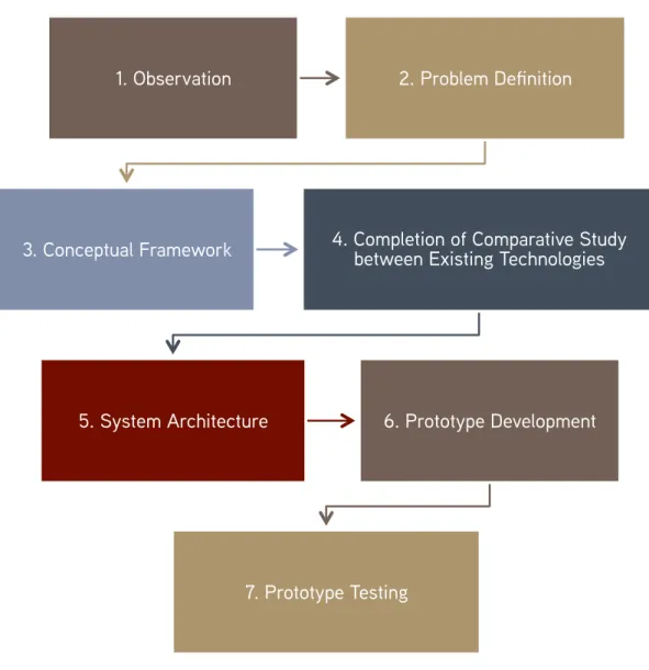
METHODOLOGY
- Observation
- Problem Definition
- Conceptual Framework
- Completion of Comparative Study between Existing Technologies
- System Architecture
- Prototype Development
- Prototype Testing
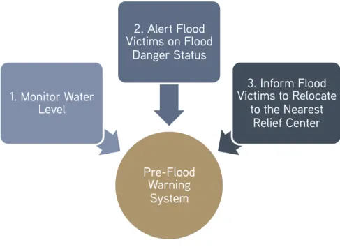
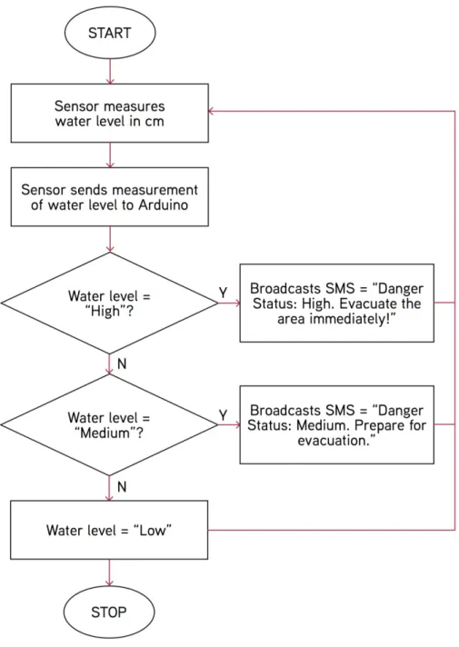
In this section, a problem statement is defined to narrow the scope of the project. The main focus of this research project is the development of an early warning system that overcomes the shortcomings of the existing system. The first phase of the system focuses on monitoring the water level on the banks of rivers to determine the state of danger.
Based on the hazard status, phase two of the system plays a significant role in alerting residents, passers-by and local authorities in the affected area of the flood hazard status. The third phase of the system involves data broadcasting, as the system informs all victims to move to the nearest emergency center immediately. The decision is made based on the application of the latest technology, the performance of the tools, and how the implementation of the technology and tools can benefit the proposed pre-flood warning system to become an effective warning system.
After the completion of the comparative study between the existing technologies and with the formulated conceptual framework as a basis, system architecture is designed for this research project. The system architecture is used to give a clear representation of how the system works with a description of the equipment that will be implemented in this project. The development of the prototype model for this research project requires the integration of hardware and software components.
Based on the results collected, continuous improvement will be made to increase the effectiveness and efficiency of the proposed system.
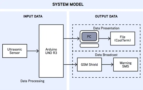
SYSTEM MODEL
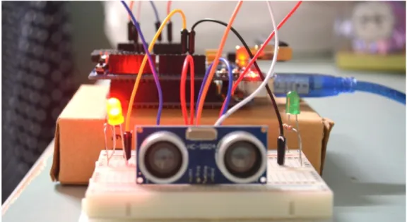
HC-SR04 Ultrasonic Sensor
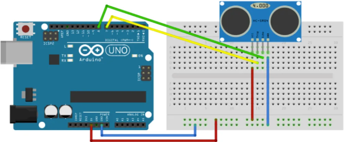
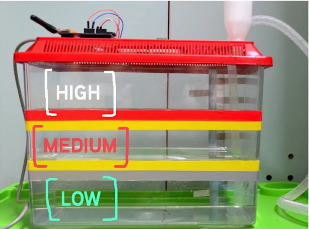
To develop the prototype system, the ultrasonic sensor is placed upside down and facing the water surface, similar to the image shown in Figure 6. The signal is reflected when it touches the water surface and received by the receiver. The sensor then records the travel time it takes for the signal to propagate from the transmitter to the water surface and bounce back to the receiver.
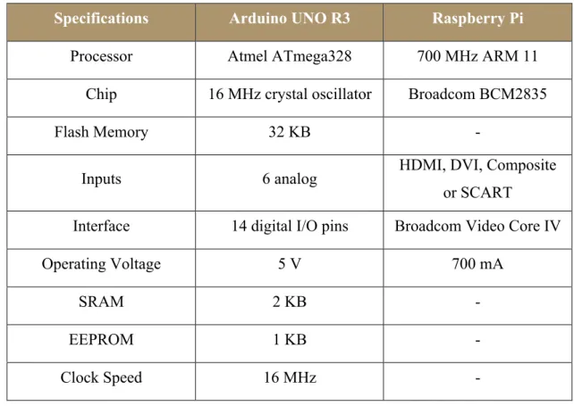
Arduino UNO R3
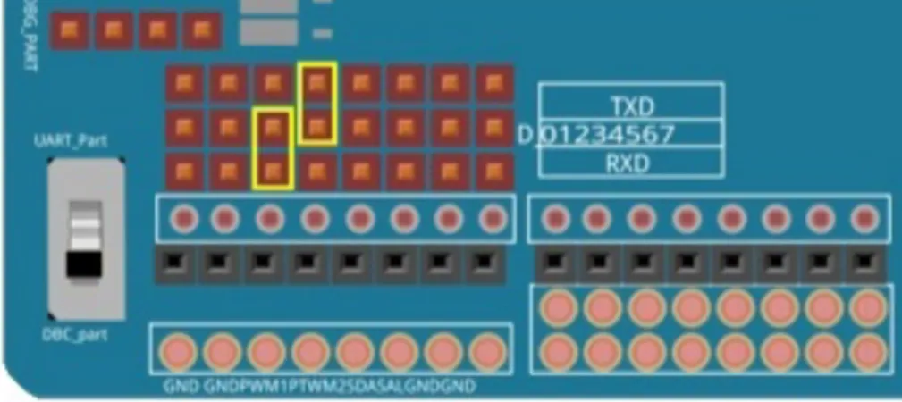
This GSM shield is designed for Arduino based on SIM900 quad band and it is used to send warning SMS to residents, local authorities and passersby. The GSM shield and Arduino are then integrated with the ultrasonic sensor via wires through the Arduino interface. The digital receive (RXD) and transmit (TXD) pins of the Arduino are set to 0 and 1 to establish connection from the Arduino to the GSM shield.
For the connection from the GSM shield to Arduino, RXD and TXD of GSM shield are set to digital pin 2 and 3. Based on the assumption made from the mobility of subscribers, using the MTSO technology, the GSM shield will be connected to the nearest cell tower where the sensor is parked. This is done to ensure that warning SMS is broadcast and delivered only to the residents, local authorities and passers-by residing in the affected flood area.
Mobile Phone
Software Components
- Arduino Software (IDE) Version 1.6.5
- CoolTerm Version 1.4.5
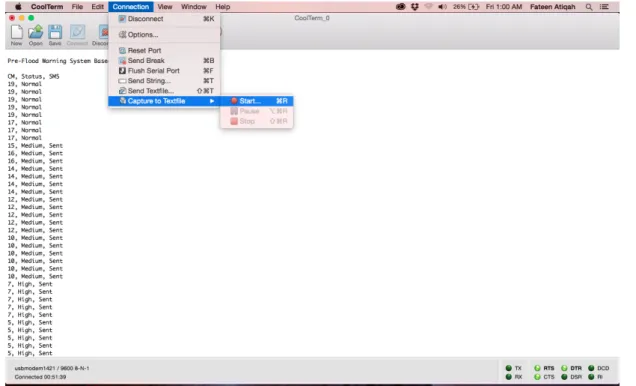
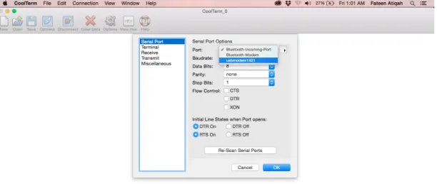
For data presentation, CoolTerm version 1.4.5 was used for the purpose of exporting the data to Microsoft Excel and generating a graph of the data collected from the ultrasound sensor. A screenshot of the CoolTerm control window showing the output of the program is shown in Figure 11. CoolTerm is a simple serial port terminal application that works by establishing a connection to the serial port that the Arduino IDE uses to communicate with the board [17].
A controlled water rise effect experiment was conducted to validate the prototype system for the proposed system architecture.
System Architecture
Therefore, Chapter 5 discusses the results, which consist of the system architecture, source code, prototype testing, problems encountered, and solutions implemented to overcome the problems. Using MTSO technology, the GSM Shield will be connected to the nearest cell tower to get a list of users registered in the specific flood area. So, warning SMS are broadcast based on the assumption of users' mobility to increase the effectiveness and efficiency of the pre-flood warning system.
The data flow diagram in Figure 13 shows the flow of the code algorithm that is programmed into the Arduino microcontroller via the IDE.
Source Code
- Establishing Connection with GSM Shield
- Send and Receive SMS
- Reading Value from Communication Port
- Data Extraction using CoolTerm
- XLS (Excel) Exports
For receiving incoming SMS, Code Snippet 4 is added inside voidloop() to ensure that the system checks for new and unread SMS every 60 seconds as shown in line 01. Executing the code in line 06 will display new and unread SMS in serial monitor. The serial monitor will display the position of unread SMS in the inbox along with the sender's phone number and accompanying messages as shown in line 05 to line 08.
A step-by-step photo screenshot to support the port configuration process for CoolTerm is shown in Figure 14 to Figure 20. As shown in Figure 14, go to Options to configure CoolTerm's network settings to connect to the same communication port as Arduino . In Terminal Options, shown in Figure 16, select Raw Mode to get the data as it is.
In Figure 18, Notify after sending text file in Send Text Options is selected to receive notifications after the process is complete. The Reduce Display Refresh Rate tab is selected in Figure 19 to minimize CoolTerm's need to reload when it retrieves new data. Then go to Connection as shown in Figure 20, hover over to Capture to Textfile and select Start to start capturing data.
Under Column data format in Figure 24, Date with MDY format is selected and the Finish button is clicked to save the settings in the Text Import wizard.
Experiment Setup
- Test 1: Accuracy Testing Objective
- Test 2: System Testing Objective
- Test 3: Performance Testing Objective
The purpose of performing this test is to determine the accuracy of the data collected by the ultrasonic sensor. In this context, the data refers to the distance measured in centimeters between the ultrasonic sensor and the surface of the water. The accuracy of the data collected by the ultrasonic sensor is determined by comparing its measurements with manual measurements using a 30 cm clear plastic flat centimeter ruler.
This shows that the ultrasonic sensor is accurate as it always recorded the distance within 1 cm. Based on the results, the data collected by the ultrasonic sensor is consistent throughout the number of trials. There is a very good correlation between the distance recorded by the ultrasonic sensor and the actual distance measured with a ruler.
The time delay for receiving new data from the ultrasonic sensor is set at an interval of 30 seconds. Based on the results, the changes in water elevation show negative velocity, which means that the water level is moving towards the ultrasonic sensor as the water level increases. The stability of the system is measured by looking at the consistency of the data collected by the ultrasonic sensor.
The reading of the water level collected by the ultrasonic sensor is also consistent until the water dropped to an extremely low level.
Problems Encountered and Solutions to Overcome
- Establishing Connection between GSM Shield and Arduino
- Ultrasonic Sensor Failed to Communicate with Arduino
- Integration of Solar Panel with Arduino
When these two components could not communicate with each other, the sensor did not record any value. The third and final problem occurred during the final stage of development for the prototype model. Initially, solar panel was included in the proposed system architecture as main supply of power to this system, as electricity supply will be cut off during the event of flooding.
However, the solar panel had to be removed and a thorough investigation and exploration work is needed to figure out how to integrate the solar panel to the Arduino board.
Conclusion
The results from the experiment conducted show that the proposed prototype system works as intended and with a success rate of 96% to 100%. the ultrasonic sensor has been proven to be able to accurately measure the water level. In conclusion, the development of the flood warning system was a success even though the solar panel is not included in the prototype system. However, in real implementation, the solar panel will be added to ensure that the system works when the power supply is being interrupted.
Moreover, by having an effective flood warning system, immediate action can be taken by local authorities, which will speed up the process of evacuating flood victims to the relief centre. Thus, millions of Ringgit in damages could be reduced along with loss of life and property and destruction of agriculture and livestock. This work was presented at the International Symposium on Mathematical and Computer Science Conference 2015.
Recommendation
- Add Solar Panel as Main Power Supply
- Implement Artificial Intelligence Concept or Expert System
Chan, “Disaster Impacts and Disaster Risk Management in Malaysia: The Case of Floods,” in Resilience and Recovery in Asian Disasters, ed: Springer, 2015, p. Ma, “Phoenix: a collaborative location information system for mobile networks,” Mathematical Problems in Engineering, vol. Nowakowski, et al., “Urbanflood common information space for early warning systems,” Procedia Computer Science, vol.
Available: http://mobiforge.com/research-analyze/global-mobile-statistics-2014-part-b-mobile-web-mobile-broadband-penetratie-3g4g-subscribers-and-ne.
![FIGURE 6. The Operation of Ultrasonic Transducer [2]](https://thumb-ap.123doks.com/thumbv2/azpdforg/10401425.0/30.892.257.672.111.472/figure-6-operation-ultrasonic-transducer-2.webp)
